MSI B450M PRO-M2 V2 User manual

1
< 1> Contents
Contents
Safety Information...........................................................................................2
Specifications...................................................................................................3
Package contents.............................................................................................6
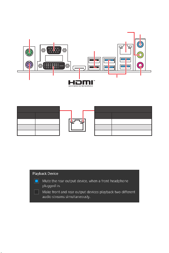
Rear I/O Panel.................................................................................................. 7
LAN Port LED Status Table.................................................................................7
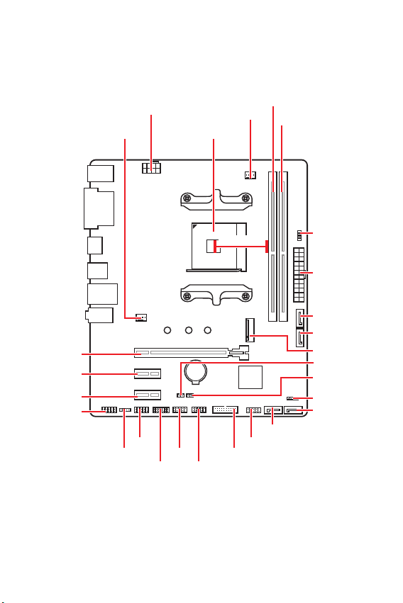
Overview of Components ................................................................................ 8
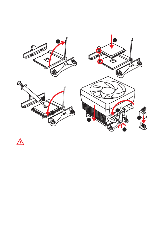
CPU Socket .........................................................................................................9
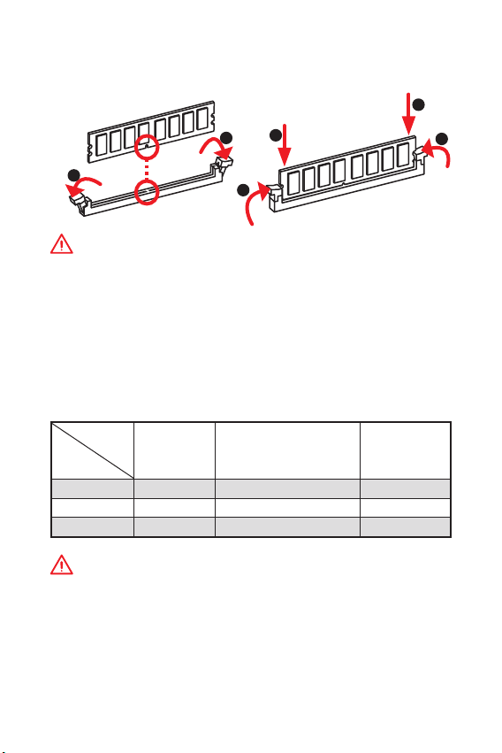
DIMM Slots........................................................................................................10
PCI_E1~3: PCIe Expansion Slots......................................................................10
JFP1, JFP2: Front Panel Connectors ...............................................................11
SATA1~4: SATA 6Gb/s Connectors....................................................................11
ATX_PWR1, CPU_PWR1: Power Connectors....................................................12
M2_1: M.2 Slot (Key M) .....................................................................................12
JUSB1~2: USB 2.0 Connectors.........................................................................13
JUSB3: USB 3.1 Gen1 Connector .....................................................................13
CPU_FAN1, SYS_FAN1: Fan Connectors..........................................................14
JTPM1: TPM Module Connector.......................................................................15
JCI1: Chassis Intrusion Connector...................................................................15
JAUD1: Front Audio Connector.........................................................................16
JCOM1: Serial Port Connector .........................................................................16
JLED1: LED strip connector .............................................................................16
JBAT1: Clear CMOS (Reset BIOS) Jumper .......................................................17
EZ Debug LED: Debug LED indicators..............................................................17
BIOS Setup.....................................................................................................18
Entering BIOS Setup.........................................................................................18
Resetting BIOS..................................................................................................19
Updating BIOS...................................................................................................19
Software Description..................................................................................... 20
Installing Windows®10.....................................................................................20
Installing Drivers ..............................................................................................20
Installing Utilities..............................................................................................20
Thank you for purchasing the MSI®B450M PRO-M2 V2
motherboard. This User Guide gives information about
board layout, component overview, BIOS setup and software
installation.

2Safety Information
Safety Information
yThe components included in this package are prone to damage from electrostatic
discharge (ESD). Please adhere to the following instructions to ensure successful
computer assembly.
yEnsure that all components are securely connected. Loose connections may cause
the computer to not recognize a component or fail to start.
yHold the motherboard by the edges to avoid touching sensitive components.
yIt is recommended to wear an electrostatic discharge (ESD) wrist strap when
handling the motherboard to prevent electrostatic damage. If an ESD wrist strap is
not available, discharge yourself of static electricity by touching another metal object
before handling the motherboard.
yStore the motherboard in an electrostatic shielding container or on an anti-static
pad whenever the motherboard is not installed.
yBefore turning on the computer, ensure that there are no loose screws or metal
components on the motherboard or anywhere within the computer case.
yDo not boot the computer before installation is completed. This could cause
permanent damage to the components as well as injury to the user.
yIf you need help during any installation step, please consult a certified computer
technician.
yAlways turn off the power supply and unplug the power cord from the power outlet
before installing or removing any computer component.
yKeep this user guide for future reference.
yKeep this motherboard away from humidity.
yMake sure that your electrical outlet provides the same voltage as is indicated on
the PSU, before connecting the PSU to the electrical outlet.
yPlace the power cord such a way that people can not step on it. Do not place
anything over the power cord.
yAll cautions and warnings on the motherboard should be noted.
yIf any of the following situations arises, get the motherboard checked by service
personnel:
Liquid has penetrated into the computer.
The motherboard has been exposed to moisture.
The motherboard does not work well or you can not get it work according to
user guide.
The motherboard has been dropped and damaged.
The motherboard has obvious sign of breakage.
yDo not leave this motherboard in an environment above 60C (140F), it may
damage the motherboard.

3
Safety Information Specifications
Specifications
CPU Supports AMD® Ryzen 1st and 2nd Generation/ Ryzen™
with Radeon™ Vega Graphics/ Athlon™ with Radeon™ Vega
Graphics Processors for Socket AM4
Chipset AMD® B450 chipset
Memory
y2x DDR4 memory slots, support up to 32GB
Supports DDR4 1866/ 2133/ 2400/ 2667 MHz by JEDEC,
and 2667/ 2800/ 2933/ 3000/ 3066/ 3200/ 3466 MHz by
A-XMP OC mode*
yDual channel memory architecture
ySupports ECC UDIMM memory (non-ECC mode)
ySupport non-ECC UDIMM memory
* Please refer www.msi.com for more information on
compatible memory.
Expansion Slots
y1 x PCIe 3.0 x16 slot (PCI_E1)
Supports x16 speed with AMD®Ryzen™ 1st and 2nd
Generation processors
Supports x8 speed with AMD®Ryzen™ with Radeon
Vega Graphics processors
Supports x4 speed with AMD®Athlon™ with Radeon™
Vega Graphics Processors
y2x PCIe 2.0 x1 slots
Onboard
Graphics
y1 x VGA port, supports a maximum resolution of
2048x1280@60HZ*
y1 x DVI-D port, supports a maximum resolution of
1920x1200@60Hz*
y1 x HDMI™ port, supports a maximum resolution of
4096x2160@24Hz*
* Only support when using AMD®Ryzen™ with Radeon™ Vega
Graphics/ Athlon™ with Radeon™ Vega Graphics and A-series
Processors
* Processors Maximum shared memory of 2048 MB
Storage
AMD® B450 Chipset
y4x SATA 6Gb/s ports*
Supports RAID 0, RAID1 and RAID 10
y1x M.2 slot (Key M)
Supports PCIe 3.0 x4 (AMD®Ryzen 1st and 2nd
Generation/ Ryzen™ with Radeon™ Vega Graphics) or
PCIe 3.0 x2 (AMD®Athlon™ with Radeon™ Vega Graphics)
and SATA 6Gb/s 2242/ 2260/ 2280 storage devices
Continued on next page

4Specifications
Continued from previous page
Audio yRealtek®ALC887 Codec
y7.1-Channel High Definition Audio
LAN 1x Realtek®8111H Gigabit LAN controller
USB
AMD® B450 Chipset
y2x USB 3.1 Gen1 (SuperSpeed USB) ports through the
internal USB 3.1 Gen1 connector
y6x USB 2.0 (High-speed USB) ports (2 ports on the back
panel, 4 ports available through the internal USB connectors)
AMD®processor
y4x USB 3.1 Gen1 (SuperSpeed USB) Type-A ports on the
back panel
Back Panel
Connectors
y1x PS/2 keyboard/ mouse combo port
y2x USB 2.0 Type-A ports
y1x VGA port
y1x DVI-D port
y1x HDMI™ port
y4x USB 3.1 Gen1 Type-A ports
y1x LAN (RJ45) port
y3x audio jacks
Internal
Connectors
y1x 24-pin ATX main power connector
y1x 8-pin ATX 12V power connector
y4x SATA 6Gb/s connectors
y2x USB 2.0 connectors (supports additional 4 USB 2.0 ports)
y1x USB 3.1 Gen1 connector (supports additional 2 USB 3.1
Gen1 ports)
y1x 4-pin CPU fan connector
y1x 4-pin system fan connector
y1x Front panel audio connector
y2x Front panel connectors
y1x TPM module connector
y1x Chassis Intrusion connector
y1x Serial port connector
y1x LED strip connector
y1x Clear CMOS jumper
I/O Controller NUVOTON 5567 Controller Chip
Continued on next page

5
Specifications Specifications
Continued from previous page
Hardware
Monitor
yCPU/System temperature detection
yCPU/System fan speed detection
yCPU/System fan speed control
Form Factor ym-ATX Form Factor
y9.6 in. x 8.1 in. (24.4 cm x 20.6 cm)
BIOS Features
y1x 128 Mb flash
yUEFI AMI BIOS
yACPI 5.0, SM BIOS 2.8
yMulti-language
Software
yDrivers
yAPP MANAGER
ySUPER CHARGER
yCOMMAND CENTER
yLIVE UPDATE 6
yMYSTIC LIGHT
yMSI SMART TOOL
yX-BOOST
yRAMDISK
yNorton™Security
yGoogle Chrome™,Google Toolbar, Google Drive
yCPU-Z MSI GAMING
Continued on next page

6Package contents
Continued from previous page
Special
Features
yAudio
Audio Boost
yStorage
Turbo M.2
StoreMI
yFan
Smart Fan Control
yLED
Mystic light SYNC
EZ DEBUG LED
yProtection
PCI-E Steel Slot
yPerformance
DDR4 Boost
Core Boost
OC Genie
yVR
VR Ready
yBIOS
Click BIOS 5
AMD FreeSync™ Ready
AMD Precision Boost OverDrive™
Package contents
Please check the contents of your motherboard package. It should contain:
yMotherboard
yDriver DVD
yQuick Installation Guide
yI/O Shielding
ySATA 6G Cable x2
yCase Badge
yVIP Card
yM.2 Screw x1
Important
If any of the above items are damaged or missing, please contact your retailer.

7
Package contents Rear I/O Panel
Rear I/O Panel
Audio 7.1-channel Configuration
To configure 7.1-channel audio, you have to connect front audio I/O module to JAUD1
connector and follow the below steps.
1. Click on the Realtek Audio Console > Advanced Settings to open the dialog below.
2. Select Mute the rear output device, when a front headphone plugged in.
3. Plug your speakers to audio jacks on rear and front I/O panel. When you plug into
a device at an audio jack, a dialogue window will pop up asking you which device is
current connected.
Link/ Activity LED
Status Description
Off No link
Yellow Linked
Blinking Data activity
Speed LED
Status Description
Off 10 Mbps connection
Green 100 Mbps connection
Orange 1 Gbps connection
LAN Port LED Status Table
PS/2 Mouse
PS/2 Keyboard
LAN
USB 3.1 Gen1
USB 2.0
DVI-D
VGA
Line-in
Line-out
Mic in

8Overview of Components
BAT1
CPU_FAN1
CPU SocketSYS_FAN1
PCI_E3
JAUD1
JTPM1
PCI_E2
PCI_E1
DIMMA1
DIMMB1
JBAT1
JCI1
JFP2
SATA2
SATA1
ATX_PWR1
CPU_PWR1
EZ Debug LED
SATA3
M2_1
SATA4
JUSB1 JUSB3
JUSB2
JLED1
JFP1
JCOM1
Overview of Components
52.00mm*
* Distance from the center of the CPU to the nearest DIMM slot.

9
Overview of Components Overview of Components
CPU Socket
Please install the CPU into the CPU socket as shown below.
Important
y
When changing the processor, the system configuration could be cleared and reset
BIOS to default values due to the AM4 processors architecture.
y
Always unplug the power cord from the power outlet before installing or removing
the CPU.
y
When installing a CPU, always remember to install a CPU heatsink. A CPU heatsink
is necessary to prevent overheating and maintain system stability.
y
Confirm that the CPU heatsink has formed a tight seal with the CPU before booting
your system.
y
Overheating can seriously damage the CPU and motherboard. Always make sure
the cooling fans work properly to protect the CPU from overheating. Be sure to apply
an even layer of thermal paste (or thermal tape) between the CPU and the heatsink to
enhance heat dissipation.
y
If you purchased a separate CPU and heatsink/ cooler, Please refer to the
documentation in the heatsink/ cooler package for more details about installation.
1
3
5
4
6
7
8
2

10 Overview of Components
DIMM Slots
Please install the memory module into the DIMM slot as shown below.
Important
y
Due to chipset resource usage, the available capacity of memory will be a little less
than the amount of installed.
y
Based on processor specification, the Memory DIMM voltage below 1.35V is
suggested to protect the processor.
y
Due to AM4 CPU/memory controller official specification limitation, the frequency
of memory modules may operate lower than the marked value under the default
state. Please refer www.msi.com for more information on compatible memory.
PCI_E1~3: PCIe Expansion Slots
Important
y
When adding or removing expansion cards, always turn off the power supply and
unplug the power supply power cable from the power outlet. Read the expansion
cards documentation to check for any necessary additional hardware or software
changes.
y
If you install a large and heavy graphics card, you need to use a tool such as MSI
Gaming Series Graphics Card Bolster to support its weight to prevent deformation of
the slot.
1
12
3
3
2
Processors
Slots
RYZEN Series Ryzen™ with Radeon™ Vega
Graphics and A-series /
Athlon™ X4
Athlon™ with
Radeon™ Vega
Graphics
PCI_E1 PCIe 3.0 x16 PCIe 3.0 x8 PCIe 3.0 x4
PCI_E2 PCIe 2.0 x1 PCIe 2.0 x1 PCIe 2.0 x1
PCI_E3 PCIe 2.0 x1 PCIe 2.0 x1 PCIe 2.0 x1

11
Overview of Components Overview of Components
SATA1~4: SATA 6Gb/s Connectors
These connectors are SATA 6Gb/s interface ports. Each connector can connect to one
SATA device.
SATA1
SATA2 SATA3
SATA4
Important
y
Please do not fold the SATA cable at a 90-degree angle. Data loss may result during
transmission otherwise.
y
SATA cables have identical plugs on either sides of the cable. However, it is
recommended that the flat connector be connected to the motherboard for space
saving purposes.
JFP1, JFP2: Front Panel Connectors
These connectors connect to the switches and LEDs on the front panel.
JFP1
Reserved
++
++
--
--
Power LED
HDD LED Reset Switch
Power Switch
1
210
9
1 HDD LED + 2 Power LED +
3 HDD LED - 4 Power LED -
5 Reset Switch 6 Power Switch
7 Reset Switch 8 Power Switch
9 Reserved 10 No Pin
+
+-
-
Speaker
Buzzer
1
JFP2
1 Speaker - 2 Buzzer +
3 Buzzer - 4 Speaker +

12 Overview of Components
ATX_PWR1, CPU_PWR1: Power Connectors
These connectors allow you to connect an ATX power supply.
24
131
12
ATX_PWR1
1 +3.3V 13 +3.3V
2 +3.3V 14 -12V
3 Ground 15 Ground
4 +5V 16 PS-ON#
5 Ground 17 Ground
6 +5V 18 Ground
7 Ground 19 Ground
8 PWR OK 20 Res
9 5VSB 21 +5V
10 +12V 22 +5V
11 +12V 23 +5V
12 +3.3V 24 Ground
5
41
8
CPU_PWR1
1 Ground 5 +12V
2 Ground 6 +12V
3 Ground 7 +12V
4 Ground 8 +12V
Important
Make sure that all the power cables are securely connected to a proper ATX power
supply to ensure stable operation of the motherboard.
M2_1: M.2 Slot (Key M)
Please install the M.2 solid-state drive (SSD) into the M.2 slot as shown below.
1
2
3
4
30

13
Overview of Components Overview of Components
JUSB3: USB 3.1 Gen1 Connector
This connector allows you to connect USB 3.1 Gen1 ports on the front panel.
1 10
1120
1Power 11 USB2.0+
2 USB3_RX_DN 12 USB2.0-
3 USB3_RX_DP 13 Ground
4 Ground 14 USB3_TX_C_DP
5 USB3_TX_C_DN 15 USB3_TX_C_DN
6 USB3_TX_C_DP 16 Ground
7 Ground 17 USB3_RX_DP
8 USB2.0- 18 USB3_RX_DN
9 USB2.0+ 19 Power
10 NC 20 No Pin
Important
Note that the Power and Ground pins must be connected correctly to avoid possible
damage.
JUSB1~2: USB 2.0 Connectors
These connectors allow you to connect USB 2.0 ports on the front panel.
1
2 10
9
1VCC 2VCC
3 USB0- 4 USB1-
5 USB0+ 6 USB1+
7 Ground 8 Ground
9 No Pin 10 NC
Important
y
Note that the VCC and Ground pins must be connected correctly to avoid possible
damage.
y
In order to recharge your iPad,iPhone and iPod through USB ports, please install
MSI®SUPER CHARGER utility.

14 Overview of Components
CPU_FAN1, SYS_FAN1: Fan Connectors
Fan connectors can be classified as PWM (Pulse Width Modulation) Mode or DC
Mode. PWM Mode fan connectors provide constant 12V output and adjust fan speed
with speed control signal. DC Mode fan connectors control fan speed by changing
voltage. When you plug a 3-pin (Non-PWM) fan to a fan connector in PWM mode, the
fan speed will always maintain at 100%, which might create a lot of noise. You can
follow the instruction below to adjust the fan connector to PWM or DC Mode.
Switching fan mode and adjusting fan speed
You can switch between PWM mode and DC mode and adjust fan speed in BIOS >
HARDWARE MONITOR.
Select PWM mode or DC mode
Important
Make sure fans are working properly after switching the PWM/ DC mode.
There are gradient points of the fan speed that allow you to
adjust fan speed in relation to CPU temperature.
Default PWM Mode
fan connector Default DC Mode fan
connector
1
CPU_FAN1
1
SYS_FAN1
PWM Mode pin definition
1 Ground 2 +12V
3 Sense 4 Speed Control Signal
DC Mode pin definition
1 Ground 2 Voltage Control
3 Sense 4 NC
Pin definition of fan connectors

15
Overview of Components Overview of Components
JTPM1: TPM Module Connector
This connector is for TPM (Trusted Platform Module). Please refer to the TPM
security platform manual for more details and usages.
1
2 14
13
1 LPC Clock 2 3V Standby power
3 LPC Reset 4 3.3V Power
5 LPC address & data pin0 6 Serial IRQ
7 LPC address & data pin1 8 5V Power
9 LPC address & data pin2 10 No Pin
11 LPC address & data pin3 12 Ground
13 LPC Frame 14 Ground
JCI1: Chassis Intrusion Connector
This connector allows you to connect the chassis intrusion switch cable.
Normal
(default)
Trigger the chassis
intrusion event
Using chassis intrusion detector
1. Connect the JCI1 connector to the chassis intrusion switch/ sensor on the chassis.
2. Close the chassis cover.
3. Go to BIOS > SETTINGS > Security > Chassis Intrusion Configuration.
4. Set Chassis Intrusion to Enabled.
5. Press F10 to save and exit and then press the Enter key to select Yes.
6. Once the chassis cover is opened again, a warning message will be displayed on
screen when the computer is turned on.
Resetting the chassis intrusion warning
1. Go to BIOS > SETTINGS > Security > Chassis Intrusion Configuration.
2. Set Chassis Intrusion to Reset.
3. Press F10 to save and exit and then press the Enter key to select Yes.

16 Overview of Components
JAUD1: Front Audio Connector
This connector allow you to connect audio jacks on the front panel.
1
2 10
9
1 MIC L 2 Ground
3 MIC R 4 NC
5 Head Phone R 6 MIC Detection
7 SENSE_SEND 8 No Pin
9 Head Phone L 10 Head Phone Detection
JCOM1: Serial Port Connector
These connectors allow you to connect the optional serial port with bracket.
1
2 10
9
1 DCD 2 SIN
3 SOUT 4 DTR
5 Ground 6 DSR
7 RTS 8 CTS
9 RI 10 No Pin
JLED1: LED strip connector
This connector allows you to connect the single color LED strip.
Important
y
This connector supports 5050 single-color LED strips with the maximum power
rating of 3A (12V). Please keeping the LED strip shorter than 2 meters to prevent
dimming.
y
Always turn off the power supply and unplug the power cord from the power outlet
before installing or removing the LED strip.
y
Please use MYSTIC LIGHT to control the extended LED strip.
1
1 +12V 2 NC
3 Signal 4 NC 1JLED1
5050 LED strip

17
Overview of Components Overview of Components
JBAT1: Clear CMOS (Reset BIOS) Jumper
There is CMOS memory onboard that is external powered from a battery located on
the motherboard to save system configuration data. If you want to clear the system
configuration, set the jumper to clear the CMOS memory.
Keep Data
(default) Clear CMOS/ Reset
BIOS
Resetting BIOS to default values
1. Power off the computer and unplug the power cord.
2. Use a jumper cap to short JBAT1 for about 5-10 seconds.
3. Remove the jumper cap from JBAT1.
4. Plug the power cord and power on the computer.
EZ Debug LED: Debug LED indicators
These LEDs indicate the status of the motherboard.
CPU - indicates CPU is not detected or fail.
DRAM - indicates DRAM is not detected or fail.
VGA - indicates GPU is not detected or fail.
BOOT - indicates booting device is not detected or fail.

18 BIOS Setup
BIOS Setup
The default settings offer the optimal performance for system stability in normal
conditions. You should always keep the default settings to avoid possible system
damage or failure booting unless you are familiar with BIOS.
Important
y
BIOS items are continuous update for better system performance. Therefore, the
description may be slightly different from the latest BIOS and should be held for
reference only. You could also refer to the HELP information panel for BIOS item
description.
y
The pictures in this chapter are for reference only and may vary from the product
you purchased.
y
The BIOS items will vary with the processor.
Entering BIOS Setup
Press Delete key, when the Press DEL key to enter Setup Menu, F11 to enter Boot
Menu message appears on the screen during the boot process.
Function key
F1: General Help
F2: Add/ Remove a favorite item
F3: Enter Favorites menu
F4: Enter CPU Specifications menu
F5: Enter Memory-Z menu
F6: Load optimized defaults
F7: Switch between Advanced mode and EZ mode
F8: Load Overclocking Profile
F9: Save Overclocking Profile
F10: Save Change and Reset*
F12: Take a screenshot and save it to USB flash drive (FAT/ FAT32 format only).
* When you press F10, a confirmation window appears and it provides the
modification information. Select between Yes or No to confirm your choice.

19
BIOS Setup BIOS Setup
Resetting BIOS
You might need to restore the default BIOS setting to solve certain problems. There
are several ways to reset BIOS:
yGo to BIOS and press F6 to load optimized defaults.
yShort the Clear CMOS jumper on the motherboard.
Important
Please refer to the Clear CMOS jumper section for resetting BIOS.
Updating BIOS
Updating BIOS with M-FLASH
Before updating:
Please download the latest BIOS file that matches your motherboard model from MSI
website. And then save the BIOS file into the USB flash drive.
Updating BIOS:
1. Press Del key to enter the BIOS Setup during POST.
2. Insert the USB flash drive that contains the update file into the computer.
3. Select the M-FLASH tab and click on Yes to reboot the system and enter the flash
mode.
4. Select a BIOS file to perform the BIOS update process.
5. After the flashing process is 100% completed, the system will reboot
automatically.
Updating the BIOS with Live Update 6
Before updating:
Make sure the LAN driver is already installed and the Internet connection is set
properly.
Updating BIOS:
1. Install and launch MSI LIVE UPDATE 6.
2. Select BIOS Update.
3. Click on Scan button.
4. Click on Download icon to download and install the latest BIOS file.
5. Click Next and choose In Windows mode. And then click Next and Start to start
updating BIOS.
6. After the flashing process is 100% completed, the system will restart
automatically.

20 Software Description
Software Description
Please download and update the latest utilities and drivers at www.msi.com
Installing Windows®10
1. Power on the computer.
2. Insert the Windows®10 installation disc/USB into your computer.
3. Press the Restart button on the computer case.
4. Press F11 key during the computer POST (Power-On Self Test) to get into Boot
Menu.
5. Select the Windows®10 installation disc/USB from the Boot Menu.
6. Press any key when screen shows Press any key to boot from CD or DVD...
message.
7. Follow the instructions on the screen to install Windows®10.
Installing Drivers
1. Start up your computer in Windows®10.
2. Insert MSI®Driver Disc into your optical drive.
3. Click the Select to choose what happens with this disc pop-up notification, then
select Run DVDSetup.exe to open the installer. If you turn off the AutoPlay feature
from the Windows Control Panel, you can still manually execute the DVDSetup.exe
from the root path of the MSI Driver Disc.
4. The installer will find and list all necessary drivers in the Drivers/Software tab.
5. Click the Install button in the lower-right corner of the window.
6. The drivers installation will then be in progress, after it has finished it will prompt
you to restart.
7. Click OK button to finish.
8. Restart your computer.
Installing Utilities
Before you install utilities, you must complete drivers installation.
1. Open the installer as described above.
2. Click the Utilities tab.
3. Select the utilities you want to install.
4. Click the Install button in the lower-right corner of the window.
5. The utilities installation will then be in progress, after it has finished it will prompt
you to restart.
6. Click OK button to finish.
7. Restart your computer.
Table of contents
Languages:
Other MSI Motherboard manuals

MSI
MSI MPG X570S EDGE MAX WIFI User manual

MSI
MSI MAG Z390M MORTAR User manual

MSI
MSI MS-7366 User manual

MSI
MSI Z87M GAMING User manual

MSI
MSI H6M-P30 (B3) User manual

MSI
MSI PRO B760-P WIFI User manual

MSI
MSI Wind Board 330 User manual

MSI
MSI RX480M2 MS-7093 User manual

MSI
MSI Z77IA-E53 series User manual

MSI
MSI MS-98H6 User manual

MSI
MSI PRO B760-P WIFI User manual

MSI
MSI MS-7260 User manual

MSI
MSI FM2-A85XMA-E35 Series User manual

MSI
MSI 845GVM2-V Series User manual

MSI
MSI H81M-E35 User manual

MSI
MSI FM2-A85XA-G43 series User manual

MSI
MSI N3050I ECO Series User manual

MSI
MSI 650GLMS User manual

MSI
MSI MS-6785 User manual

MSI
MSI 890FXA-GD70 series User manual