MSI B550M PRO-VDH WIFI User manual

I
Quick Start
Quick Start
Thank you for purchasing the MSI® B550M PRO-VDH motherboard.
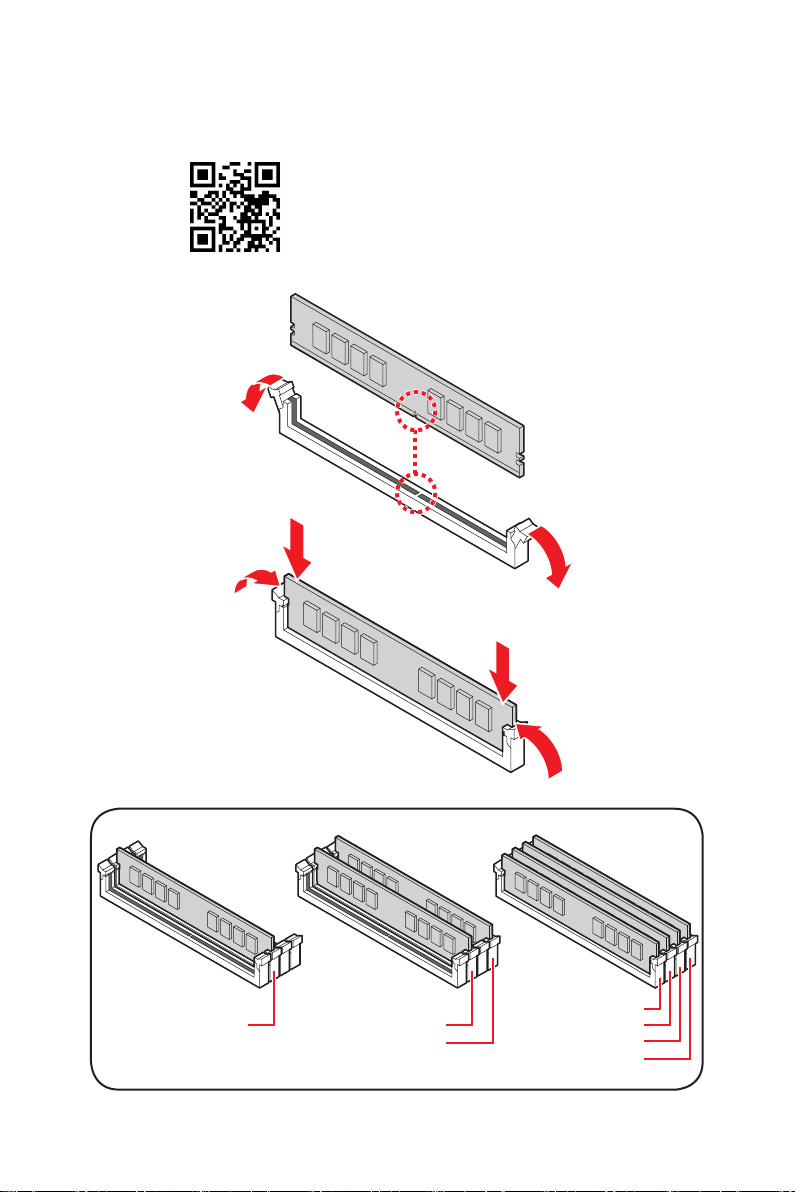
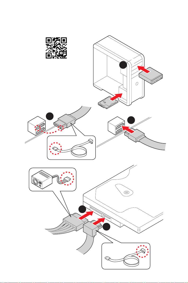
This Quick Start section provides demonstration diagrams about
how to install your computer. Some of the installations also provide
video demonstrations. Please link to the URL to watch it with the web
browser on your phone or tablet. You may have even link to the URL
by scanning the QR code.
Kurzanleitung
Danke, dass Sie das MSI® B550M PRO-VDH Motherboard gewählt
haben. Dieser Abschnitt der Kurzanleitung bietet eine Demo zur
Installation Ihres Computers. Manche Installationen bieten auch
die Videodemonstrationen. Klicken Sie auf die URL, um diese
Videoanleitung mit Ihrem Browser auf Ihrem Handy oder Table
anzusehen. Oder scannen Sie auch den QR Code mit Ihrem Handy,
um die URL zu öffnen.
Présentation rapide
Merci d’avoir choisi la carte mère MSI® B550M PRO-VDH. Ce manuel
fournit une rapide présentation avec des illustrations explicatives
qui vous aideront à assembler votre ordinateur. Des tutoriels vidéo
sont disponibles pour certaines étapes. Cliquez sur le lien fourni
pour regarder la vidéo sur votre téléphone ou votre tablette. Vous
pouvez également accéder au lien en scannant le QR code qui lui est
associé.
Быстрый старт
B550M PRO-
VDH

II Quick Start
1
2
3
6
4
5
7
8
9
https://youtu.be/Xv89nhFk1vc
⚽
CPU_FAN1
Installing a Processor/ Installation des Prozessors/ Installer un
processeur/ Установка процессора

III
Quick Start
1
23
⚠
Important
remove the retention module first and then install the heatsink.
installieren.
Si vous voulez installer un ventirad pour processeur à vis, veuillez suivre les
ventirad.

IV Quick Start
DIMMA2 DIMMA2
DIMMB2
DIMMA1
DIMMA2
DIMMB1
DIMMB2
http://youtu.be/T03aDrJPyQs
⚽
Installing DDR4 memory/ Installation des DDR4-Speichers/
Installer une mémoire DDR4/ Установка памяти DDR4

V
Quick Start
http://youtu.be/DPELIdVNZUI
⚽
HDD LED
RESET SW
HDD LED
HDD LED +
POWER LED +
POWER LED
1
2 10
9
+
+
+
+
Power LED
HDD LED Reset Switch
Reserved
Power Switch
JFP1
1 HDD LED + 2 Power LED +
3 4
5 Reset Switch 6 Power Switch
7 Reset Switch 8 Power Switch
9 Reserved 10 No Pin
RESET SW
POWER SW
POWER LED+
POWER LED-
HDD LED
JFP1
Connecting the Front Panel Header/ Anschließen der
Frontpanel-Stiftleiste/ Connecter un connecteur du panneau
avant/ Подключение разъемов передней панели

VI Quick Start
BAT1
2
Torque:
3 kgf·cm*
*3 kgf·cm
= 0.3 N·m
= 2.6 lbf·in
2
1
https://youtu.be/wWI6Qt51Wnc
⚽
Installing the Motherboard/ Installation des Motherboards/
Installer la carte mère/ Установка материнской платы

VII
Quick Start
ATX_PWR1
CPU_PWR1
http://youtu.be/gkDYyR_83I4
⚽
Connecting the Power Connectors/ Stromanschlüsse
anschliessen/ Connecter les câbles du module d’alimentation/
Подключение разъемов питания

VIII Quick Start
http://youtu.be/RZsMpqxythc
Youtube
⚽
1
23
4
5
Installing SATA Drives/ Installation der SATA-Laufwerke/
Installer le disque dur SATA/ Установка дисков SATA

IX
Quick Start
http://youtu.be/mG0GZpr9w_A
1
2
3
4
5
6
⚽
Installing a Graphics Card/ Einbau der Grafikkarte/ Installer
une carte graphique/ Установка дискретной видеокарты

XQuick Start
Processor with integrated graphics
Connecting Peripheral Devices/ Peripheriegeräte/ Connecter
un périphérique anschliessen/ Подключение периферийных
устройств

XI
Quick Start
4
3
12
Power On/ Einschalten/ Mettre sous-tension/ Включение
питания

XII Quick Start
NOTE

1
Contents
Contents
Safety Information................................................................................................. 2
Specifications......................................................................................................... 3
Package contents .................................................................................................. 8
Rear I/O Panel ....................................................................................................... 9
LAN Port LED Status Table .................................................................................... 9
Realtek Audio Console ........................................................................................... 9
Overview of Components .................................................................................... 11
Processor Socket ................................................................................................. 12
DIMM Slots............................................................................................................ 13
PCI_E1~3: PCIe Expansion Slots.......................................................................... 14
SATA1~4: SATA 6Gb/s Connectors....................................................................... 14
M2_1~2: M.2 Slots (Key M) ................................................................................... 15
JFP1, JFP2: Front Panel Connectors................................................................... 17
JAUD1: Front Audio Connector ............................................................................ 17
CPU_PWR1, ATX_PWR1: Power Connectors....................................................... 18
................................................. 19
JUSB2: USB 3.2 Gen 1 5Gbps Connector ............................................................. 19
JUSB3~4: USB 2.0 Connectors............................................................................. 20
JTPM1: TPM Module Connector........................................................................... 20
CPU_FAN1, PUMP_FAN1, SYS_FAN1~3: Fan Connectors.................................. 21
JCI1: Chassis Intrusion Connector....................................................................... 22
JBAT1: Clear CMOS (Reset BIOS) Jumper........................................................... 23
JCOM1: Serial Port Connector ............................................................................. 23
JRGB1~2: RGB LED connector............................................................................. 24
JRAINBOW1~2: Addressable RGB LED connectors ............................................ 25
EZ Debug LED....................................................................................................... 26
LED_SW1: EZ LED Control................................................................................... 26
Installing OS, Drivers & Utilities ......................................................................... 27
UEFI BIOS............................................................................................................. 28
BIOS Setup............................................................................................................ 29
Entering BIOS Setup............................................................................................. 29
Resetting BIOS...................................................................................................... 30
Updating BIOS....................................................................................................... 30
EZ Mode ................................................................................................................ 32
Advanced Mode .................................................................................................... 35
OC Menu................................................................................................................ 36

2Safety Information
Safety Information
∙The components included in this package are prone to damage from electrostatic
discharge (ESD). Please adhere to the following instructions to ensure successful
computer assembly.
∙Ensure that all components are securely connected. Loose connections may cause
the computer to not recognize a component or fail to start.
∙Hold the motherboard by the edges to avoid touching sensitive components.
∙It is recommended to wear an electrostatic discharge (ESD) wrist strap when
handling the motherboard to prevent electrostatic damage. If an ESD wrist strap is
not available, discharge yourself of static electricity by touching another metal object
before handling the motherboard.
∙
pad whenever the motherboard is not installed.
∙Before turning on the computer, ensure that there are no loose screws or metal
components on the motherboard or anywhere within the computer case.
∙Do not boot the computer before installation is completed. This could cause
permanent damage to the components as well as injury to the user.
∙If you need help during any installation step, please consult a certified computer
technician.
∙Always turn off the power supply and unplug the power cord from the power outlet
before installing or removing any computer component.
∙Keep this user guide for future reference.
∙Keep this motherboard away from humidity.
∙Make sure that your electrical outlet provides the same voltage as is indicated on
the PSU, before connecting the PSU to the electrical outlet.
∙Place the power cord such a way that people can not step on it. Do not place
anything over the power cord.
∙All cautions and warnings on the motherboard should be noted.
∙If any of the following situations arises, get the motherboard checked by service
personnel:
▪Liquid has penetrated into the computer.
▪The motherboard has been exposed to moisture.
▪The motherboard does not work well or you can not get it work according to user
guide.
▪The motherboard has been dropped and damaged.
▪The motherboard has obvious sign of breakage.
∙Do not leave this motherboard in an environment above 60°C (140°F), it may damage
the motherboard.

3
Specifications
Specifications
CPU Supports AM4 socket 3rd Gen AMD Ryzen™ processors, and
future AMD Ryzen™ processors with BIOS update
Chipset AMD B550 Chipset
Memory
∙4x DDR4 memory slots, support up to 128GB*
▪Supports DDR4 1866/ 2133/ 2400/ 2667/ 2800/ 2933/
3000/ 3066/ 3200 MHz by JEDEC
▪Supports DDR4 2667/ 2800 /2933 /3000 /3066 /3200
/3466 /3600/ 3733 /3866 /4000 /4133 /4266 /4400+ MHz by
▫1DPC 1R max speed 4400 MHZ
▫1DPC 2R max speed 3733 MHZ
▫2DPC 1R max speed 3866 MHZ
▫2DPC 2R max speed 3466 MHZ
∙Dual channel memory architecture
∙
∙Supports ECC UDIMM memory
∙
* Please refer www.msi.com for more information on compatible memory.
Expansion Slot
∙1x PCIe 3.0/ 4.0 x16 slot (PCI_E1)*
∙2x PCIe 3.0 x1 slots
* The supported specification depends on installed processor.
Onboard Graphics
∙1x VGA port, supports resolution of 2048x1536 @50Hz,
2048x1280 @60Hz, 1920x1200 @60Hz*
∙1x DisplayPort, supports a maximum resolution of
4096x2160 @60Hz*
∙1x HDMI port, supports a maximum resolution of
4096x2160 @24Hz*
∙Maximum shared memory of 16 GB
* Available for the processor with integrated graphics.
Continued on next page

4Specifications
Continued from previous page
Storage
AMD B550 Chipset
∙4x SATA 6Gb/s ports
∙2x M.2 slots (Key M)
▪M2_1 slot (from processor)
▫Supports PCIe 4.0/ 3.0 x4 *
▫Supports SATA 6Gb/s
▫Supports 2242/ 2260/ 2280 storage devices
▪M2_2 slot (from B550 chipset)
▫Supports PCIe 3.0x4
▫Supports 2242/ 2260/ 2280 storage devices
* The supported specification depends on installed processor.
RAID
∙Supports RAID 0, RAID 1 and RAID 10 for SATA storage
devices
∙Supports RAID 0 and RAID 1 for M.2 NVMe storage devices
USB
AMD B550 Chipset
▪3x USB 3.2 Gen 1 5Gbps ports
connector, and 2 ports are available through the internal
USB 3.2 Gen 1 5Gbps connector)
▪
ports through the internal USB 2.0 connectors)
AMD Processor
▪
panel
Audio Realtek® ALC892 Codec
▪
LAN ∙1x Realtek® RTL8111HN 1Gbps LAN controller
Continued on next page

5
Specifications
Continued from previous page
Internal Connectors
∙
∙
∙4x SATA 6Gb/s connectors
∙
∙
∙1x USB 3.2 Gen 1 5Gbps connector (supports additional 2
USB 3.2 Gen 1 5Gbps ports)
∙2x USB 2.0 connectors (supports additional 4 USB 2.0
ports)
∙
∙
∙
∙1x Front panel audio connector
∙2x System panel connectors
∙1x Serial port connector
∙1x Chassis Intrusion connector
∙
∙
∙1xTPM module connector
∙1x Clear CMOS jumper
LED Features ∙1x EZ LED Control switch
∙4x EZ Debug LED
Back Panel
Connectors
∙1x Flash BIOS Button
∙1x VGA port
∙1x Display port
∙1x HDMI port
∙
∙1x PS/2 keyboard/ mouse combo port
∙
∙1x LAN (RJ45) port
∙3x Audio jacks
I/O Controller
Continued on next page

6Specifications
Continued from previous page
Hardware Monitor
∙CPU/ System/ Chipset temperature detection
∙CPU/ System/ Pump fan speed detection
∙CPU/ System/ Pump fan speed control
Form Factor ∙
∙9.6 in. x 9.6 in. (24.4 cm x 24.4 cm)
BIOS Features
∙1x 256 Mb flash
∙UEFI AMI BIOS
∙ACPI 6.0, SMBIOS 2.8
∙
Software
∙Drivers
∙DRAGON CENTER
∙
∙Google Chrome™, Google Toolbar, Google Drive
∙Norton™ Internet Security Solution
Dragon Center
Features
∙Mystic Light
∙User Scenario
∙Hardware Monitor
∙True Color
∙Live Update
∙Speed Up
∙Smart Tool
∙Super Charger
Please refer to http://download.msi.
com/manual/mb/DRAGONCENTER2.
pdf for more details.
Continued on next page

7
Specifications
Continued from previous page
Special Features
∙Audio
▪Audio Boost
∙Cooling
▪Pump Fan
▪Smart Fan Control
∙LED
▪Mystic Light Extension (RAINBOW/RGB)
▪EZ LED Control
▪EZ DEBUG LED
∙Performance
▪DDR4 Boost
▪Core Boost
▪
∙Protection
▪
∙Experience
▪Dragon Center
▪Click BIOS 5
▪Flash BIOS Button

8Package contents
Package contents
Please check the contents of your motherboard package. It should contain:
Motherboard
Cable SATA 6G cables
(2 cables/pack) 1
Accessories
M.2 screws (3 pcs./pack) 1
Case badge 1
Product registration card 1
Application Driver DVD 1
Documentation
Quick installation guide 1
MSI components compatibility & reward
program card 1
⚠
Important
If any of the above items are damaged or missing, please contact your retailer.
Other manuals for B550M PRO-VDH WIFI
2
Table of contents
Languages:
Other MSI Motherboard manuals

MSI
MSI MS-98N9 User manual

MSI
MSI MS-7156 User manual

MSI
MSI PRO B760-P WIFI User manual

MSI
MSI H61MU-E35 series User manual

MSI
MSI 790GX-G65 Series User manual

MSI
MSI 865GM2-LS - Motherboard - Micro ATX User manual

MSI
MSI K8N Neo3 MS-7135 User manual

MSI
MSI PRO B760-VC WIFI User manual

MSI
MSI MEG Z590I UNIFY User manual

MSI
MSI B150-ICAFE/ H110 PC MATE User manual