MSI B450M-A PRO MAX User manual

B450M-A PRO MAX II
Motherboard
User Guide
Benutzerhandbuch
Manuel d’utilisation

1
Contents
Quick Start..................................................................................................................... 2
Specifications.............................................................................................................. 15
Special Features......................................................................................................... 18
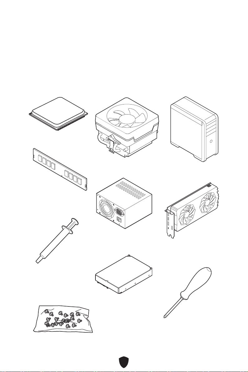
Package Contents ...................................................................................................... 19
Back Panel Connectors ............................................................................................. 20
LAN Port LED Status Table .................................................................................. 21
Audio Jacks Connection ....................................................................................... 21
Overview of Components........................................................................................... 23
CPU Socket ........................................................................................................... 24
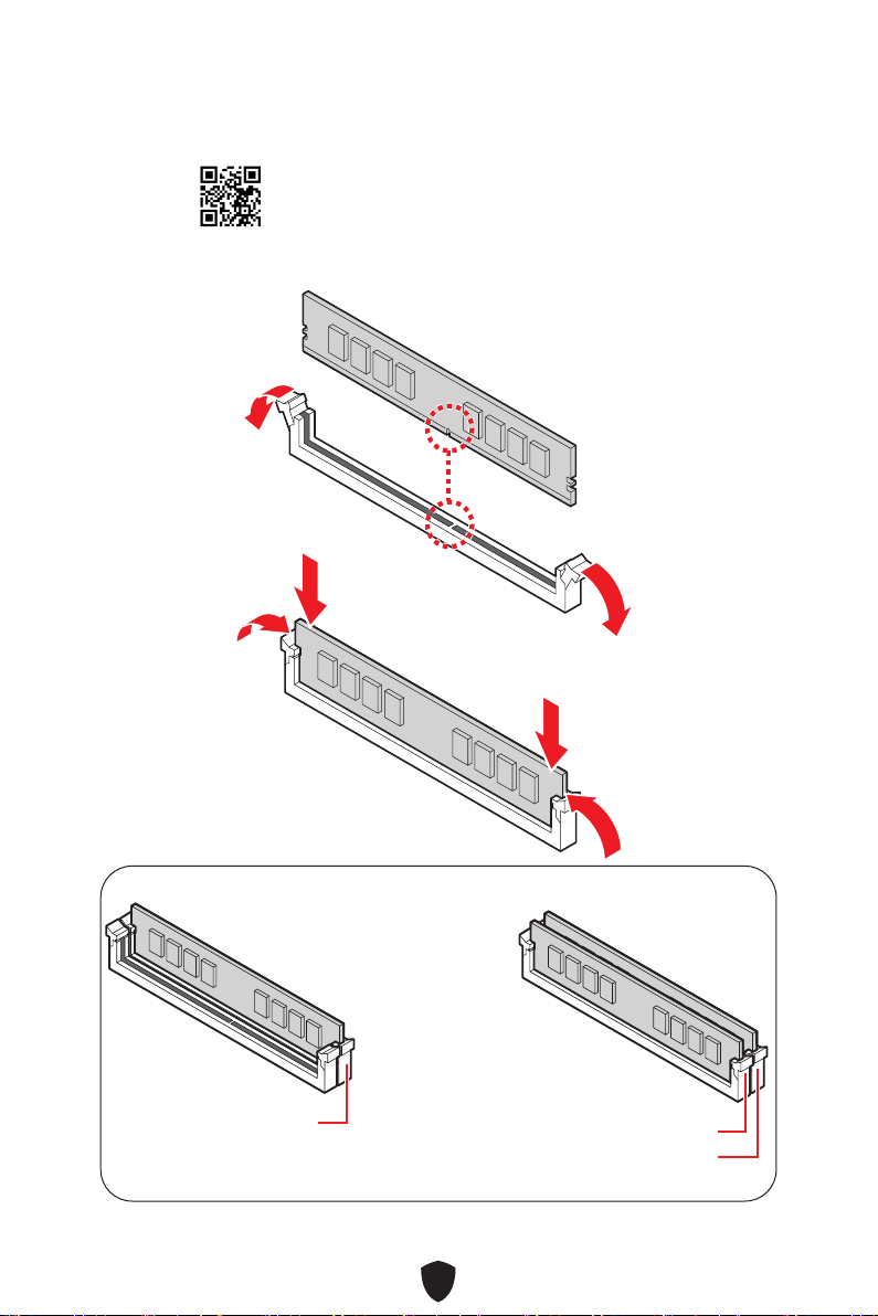
DIMM Slots............................................................................................................ 25
PCI_E1~2: PCIe Expansion Slots.......................................................................... 26
M2_1: M.2 Slot (Key M)......................................................................................... 27
SATA1~4: SATA 6Gb/s Connectors....................................................................... 28
JAUD1: Front Audio Connector ............................................................................ 29
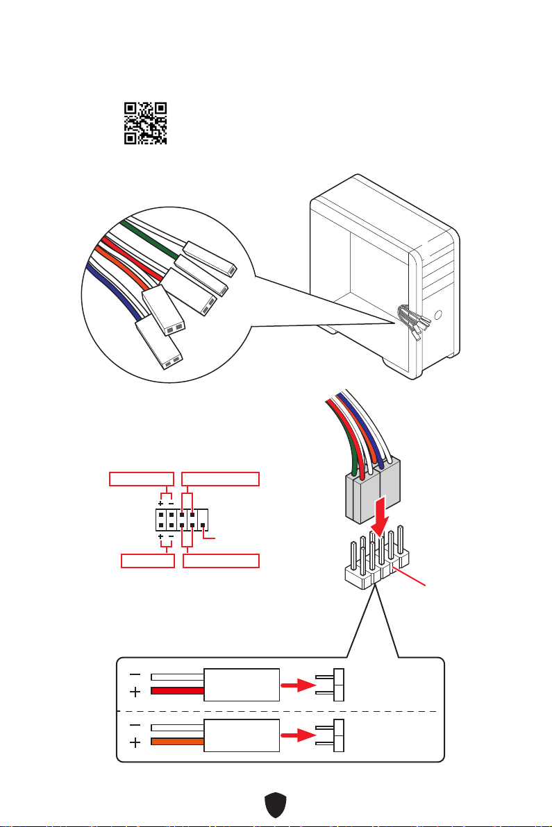
JFP1, JFP2: Front Panel Connectors................................................................... 29
ATX_PWR1, CPU_PWR1: Power Connectors....................................................... 30
JCI1: Chassis Intrusion Connector....................................................................... 31
JCOM1 : Serial Port connector............................................................................. 31
JUSB3: USB 3.2 Gen 1 Connector ........................................................................ 32
JUSB1~2: USB 2.0 Connectors............................................................................. 33
JTPM1: TPM Module Connector .......................................................................... 33
CPU_FAN1, SYS_FAN1: Fan Connectors............................................................. 34
JBAT1: Clear CMOS (Reset BIOS) Jumper........................................................... 35
............................................................................................ 36
Installing OS, Drivers & MSI Center.......................................................................... 37
Installing Drivers with MSI Driver Utility Installer............................................... 38
UEFI BIOS.................................................................................................................... 41
BIOS Setup............................................................................................................ 42
Resetting BIOS...................................................................................................... 43
Updating BIOS....................................................................................................... 43
English

2
Quick Start
Thank you for purchasing a new motherboard from MSI®. This Quick Start section
provides demonstration diagrams about how to install your computer. Some of the
installations also provide video demonstrations. Please link to the URL to watch it
with the web browser on your phone or tablet. You may have even link to the URL by
scanning the QR code.
Preparing Tools and Components
AMD® AM4 CPU
AM4 CPU Fan
DDR4 Memory
Graphics Card
SATA Hard Disk Drive
Phillips Screwdriver
Chassis
Power Supply Unit
A Package of Screws
Thermal Paste

3
Safety Information
The components included in this package are prone to damage from electrostatic
discharge (ESD). Please adhere to the following instructions to ensure successful
computer assembly.
Ensure that all components are securely connected. Loose connections may cause
the computer to not recognize a component or fail to start.
Hold the motherboard by the edges to avoid touching sensitive components.
It is recommended to wear an electrostatic discharge (ESD) wrist strap when
handling the motherboard to prevent electrostatic damage. If an ESD wrist strap
is not available, discharge yourself of static electricity by touching another metal
object before handling the motherboard.
Store the motherboard in an electrostatic shielding container or on an anti-static
pad whenever the motherboard is not installed.
Before turning on the computer, ensure that there are no loose screws or metal
components on the motherboard or anywhere within the computer case.
Do not boot the computer before installation is completed. This could cause
permanent damage to the components as well as injury to the user.
If you need help during any installation step, please consult a certified computer
technician.
Always turn off the power supply and unplug the power cord from the power outlet
before installing or removing any computer component.
Keep this user guide for future reference.
Keep this motherboard away from humidity.
Make sure that your electrical outlet provides the same voltage as is indicated on
the PSU, before connecting the PSU to the electrical outlet.
Place the power cord such a way that people can not step on it. Do not place
anything over the power cord.
All cautions and warnings on the motherboard should be noted.
If any of the following situations arises, get the motherboard checked by service
personnel:
• Liquid has penetrated into the computer.
• The motherboard has been exposed to moisture.
• The motherboard does not work well or you can not get it work according to user
guide.
• The motherboard has been dropped and damaged.
• The motherboard has obvious sign of breakage.
Do not leave this motherboard in an environment above 60°C (140°F), it may damage
the motherboard.

4
Case stand-off notification
To prevent damage to the motherboard, any unnecessary mounting stand-off between
the motherboard circuits and the computer case is prohibited. The Case standoff keep
out zone signs will be marked on the backside of motherboard (as shown below) to
serve as a warning to user.
Avoid collision notification
Protective paint is printed around each screw hole to prevent parts from being
scratched.
* The illustration above is for reference only and may vary from the motherboard you
purchased.

5
Installing a Processor
https://youtu.be/Xv89nhFk1vc 11
22
33
44
55
66
77
88
99

6
Important
If you are installing the screw-type CPU heatsink, please follow the figure below to
remove the retention module first and then install the heatsink.
11
22
33

7
Installing DDR4 memory
http://youtu.be/T03aDrJPyQs
DIMMB1 DIMMA1
DIMMB1

8
Connecting the Front Panel Header
HDD LED
RESET SW
http://youtu.be/DPELIdVNZUI
JFP1
HDD LED HDD LED -
HDD LED +
POWER LED -
POWER LED +
POWER LED
RESET SW
POWER SW
POWER LED+
POWER LED-
HDD LED
1
2 10
9
Power LED
Reserved
Power Switch
JFP1
Reset SwitchHDD LED

9
Installing the Motherboard
BAT 1
Torque:
3 kgf·cm*
*3 kgf·cm
= 0.3 N·m
= 2.6 lbf·in
33
22
https://youtu.be/wWI6Qt51Wnc
11

10
Connecting the Power Connectors
ATX_PWR1
CPU_PWR1
http://youtu.be/gkDYyR_83I4

11
Installing SATA Drives
http://youtu.be/RZsMpqxythc
11
2233
44
55

12
Installing a Graphics Card
http://youtu.be/mG0GZpr9w_A
11
22
33
44
55
66

13
Connecting Peripheral Devices

14
Power On
44
33
1122

15
Specifications
CPU
Supports AMD Ryzen™ 5000 Series, 5000 G-Series, 4000
G-Series, 3000 Series, 3000 G-Series, 2000 Series, 2000
G-Series and 1000 Series Desktop Processor and Athlon™
with Radeon™ Vega Graphics desktop processors
Supports Processor socket AM4
* Please go to www.msi.com to get the newest support status as new processors
are released.
Chipset AMD B450 Chipset
Memory
2x DDR4 memory slots, support up to 64GB*
Supports DDR4 1866/ 2133/ 2400/ 2667/ 2800/ 2933/ 3000/
3066/ 3200 MHz by JEDEC
Supports DDR4 2667/ 2800 /2933 /3000 /3066 /3200 /3466
/3600/ 3733 /3866 /4000 /4133+ MHz by A-XMP OC MODE
Supports Dual-Channel mode
Supports non-ECC, UDIMM memory
Supports ECC UDIMM memory (non-ECC mode)
Supports un-buffered memory
* Please refer to www.msi.com for more information on compatible memory.
Expansion Slots
1x PCIe x16 slot
• PCI_E1 slot (From CPU)
• AMD Ryzen™ 5000 Series, 5000 G-Series, 4000
G-Series, 3000 Series, 2000 Series, and 1000 Series
desktop processors support up to PCIe 3.0 x16
• AMD Ryzen™ 3000 G-Series and 2000 G-Series
desktop processors support up to PCIe 3.0 x8
• Athlon™ with Radeon™ Vega Graphics desktop
processors support up to PCIe 3.0 x4
1x PCIe x1 slot
• PCI_E2 slot (From B450 chipset)
• Supports PCIe 2.0 x1
Onboard Graphics
1x DVI-D port, supports a maximum resolution of
1920x1200 60Hz*/ **
1x HDMI™ 1.4 port, supports a maximum resolution of 4K
24Hz*/**
* Available only on processors featuring integrated graphics.
** Graphics specifications may vary depending on the CPU installed.
Continued on next column

16
Continued from previous column
SATA Ports 4x SATA 6Gb/s ports
• SATA1~4 (From B450 chipset)
M.2 SSD Slots
1x M.2 slot (Key M)
• M2_1 slot (From CPU)
• Supports PCIe 3.0 x4 (AMD Ryzen™ 5000 Series, 5000
G-Series, 4000 G-Series, 3000 Series, 3000 G-Series,
2000 Series, 2000 G-Series, and 1000 Series desktop
processors)
• Supports PCIe 3.0 x2 (Athlon™ with Radeon™ Vega
Graphics)
• Supports SATA 6Gb/s
• Supports 2242/ 2260/ 2280 storage device
RAID Supports RAID 0, RAID 1 and RAID 10 for SATA storage
devices
Audio Realtek® ALC897 Codec
7.1-Channel High Definition Audio
LAN 1x Realtek® 8125 2.5Gbps LAN controller
Power Connectors 1x 24-pin ATX main power connector
1x 4-pin +12V power connector
Internal USB
Connectors
1x USB 3.2 Gen 1 5Gbps connector (From B450 chipset)
• Supports additional 2 USB 3.2 Gen 1 5Gbps ports
2x USB 2.0 connectors (From B450 chipset)
• Supports additional 4 USB 2.0 ports
Fan Connectors 1x 4-pin CPU fan connector
1x 4-pin system fan connector
System Connectors
1x Front panel audio connector
2x System panel connectors
1x Chassis Intrusion connector
1x TPM module connector
1x Serial port connector
Jumpers 1x Clear CMOS jumper
Continued on next column

17
Continued from previous column
Back Panel
Connectors
1x PS/2 Mouse port
1x PS/2 Keyboard port
1x DVI-D port
1x HDMI™ port
4x USB 3.2 Gen 1 5Gbps Type-A ports (From CPU)
1x 2.5G LAN (RJ45) port
2x USB 2.0 Type-A ports (From B450 chipset)
3x audio jacks
I/O Controller NUVOTON NCT6687R Controller Chip
Hardware Monitor
CPU/ System temperature detection
CPU/ System fan speed detection
CPU/ System fan speed control
Form Factor Micro-ATX Form Factor
7.9 in. x 9.3 in. (200 mm x 236 mm)
BIOS Features
1x 256 Mb flash
UEFI AMI BIOS
ACPI 6.1, SMBIOS 2.8
Multi-language
Software
Drivers
MSI Center
CPU-Z MSI GAMING
Norton 360

18
Special Features
Audio
• Audio Boost
Network
• 2.5G LAN
• LAN Manager
Performance
• Core Boost
• Memory Boost
Experience
• MSI Center
Other manuals for B450M-A PRO MAX
1
Table of contents
Languages:
Other MSI Motherboard manuals

MSI
MSI MS-98H7 User manual

MSI
MSI Intel 500 Series User manual

MSI
MSI MAG B560M MORTAR WIFI User manual

MSI
MSI G52-73501X1 User manual

MSI
MSI MEG X570S UNIFY-X MAX User manual

MSI
MSI 760GA-P43 FX User manual

MSI
MSI K8NNeo4 Platinum Series User manual

MSI
MSI H67MA-E35 series User manual

MSI
MSI PRO B660M-A WIFI DDR4 User manual

MSI
MSI B350 TOMAHAWK User manual

MSI
MSI K9MM-V User manual

MSI
MSI MS-7865 User manual

MSI
MSI 880GM-E43 Series User manual

MSI
MSI X58A-GD45 series User manual

MSI
MSI H8M-P32 User manual

MSI
MSI K9VGM-V Series User manual

MSI
MSI K7N2GM2-ILSR User manual

MSI
MSI Z87-G43 GAMING User manual

MSI
MSI 610BF User manual

MSI
MSI A520M PRO-C DASH User manual