MSI K7N2GM-V User manual

i
FCC-B Radio Frequency Interference Statement
This equipment has been tested and found to comply with the limits for a class B digital device, pursuant to part 15 of
the FCC rules. These limits are designed to provide reasonable protection against harmful interference when the
equipment is operated in a commercial environment. This equipment generates, uses and can radiate radio frequency
energy and, if not installed and used in accordance with the instruction manual, may cause harmful interference to
radio communications. Operation of this equipment in a residential area is likely to cause harmful interference, in
which case the user will be required to correct the interference at his own expense.
Notice 1
The changes or modifications not expressly approved by the party responsible for compliance could void the user’s
authority to operate the equipment.
Notice 2
Shielded interface cables and A.C. power cord, if any, must be used in order to comply with the emission limits.
VOIR LANOTICE D’NSTALLATIONAVANT DE RACCORDER AU RESEAU.
Micro-Star International
MS-7119
This device complies with Part 15 of the FCC Rules. Operation is subject to the following two conditions:
(1) this device may not cause harmful interference, and
(2) this device must accept any interference received, including interference that may cause undesired operation
G52-M7119X1

ii
Copyright Notice
The material in this document is the intellectual property of MICRO-STAR INTERNATIONAL. We take every care in
the preparation of this document, but no guarantee is given as to the correctness of its contents. Our products are
under continual improvement and we reserve the right to make changes without notice.
Trademarks
All trademarks are the properties of their respective owners.
AMD, Athlon™ Athlon™XP, Thoroughbred™ and Duron™ are registered trademarks of AMD Corporation.
Intel® and Pentium® are registered trademarks of Intel Corporation.
PS/2 and OS® 2 are registered trademarks of International Business Machines Corporation.
Microsoft® is a registered trademark of Microsoft Corporation. Windows® 98/2000/NT/XP are registered trademarks
of Microsoft Corporation.
NVIDIA, the NVIDIA logo, DualNet, and nForce are registered trademarks or trademarks of NVIDIA Corporation in the
United States and/or other countries.
Netware® is a registered trademark of Novell, Inc.
Award® is a registered trademark of Phoenix Technologies Ltd.
AMI® is a registered trademark of American Megatrends Inc.
Kensington and MicroSaver are registered trademarks of the Kensington Technology Group.
PCMCIA and CardBus are registered trademarks of the Personal Computer Memory Card International Association.
Revision History
Revision Revision History Date
V1.0 First release for PCB v1.0 with nForce2 IGP-64 & nForce MCP2SL November 2004

iii
Safety Instructions
1. Always read the safety instructions carefully.
2. Keep this User Manual for future reference.
3. Keep this equipment away from humidity.
4. Lay this equipment on a reliable flat surface before setting it up.
5. The openings on the enclosure are for air convection hence protects the equipment from overheating. Do not
cover the openings.
6. Make sure the voltage of the power source and adjust properly 110/220V before connecting the equipment to the
power inlet.
7. Place the power cord such a way that people can not step on it. Do not place anything over the power cord.
8. Always Unplug the Power Cord before inserting any add-on card or module.
9. All cautions and warnings on the equipment should be noted.
10. Never pour any liquid into the opening that could damage or cause electrical shock.
11. If any of the following situations arises, get the equipment checked by a service personnel:
- The power cord or plug is damaged.
- Liquid has penetrated into the equipment.
- The equipment has been exposed to moisture.
- The equipment does not work well or you can not get it work according to User Manual.
- The equipment has dropped and damaged.
- The equipment has obvious sign of breakage.
12. Do not leave this equipment in an environment unconditioned, storage temperature above 60° C (140°F), it may
damage the equipment.
CAUTION: Danger of explosion if battery is incorrectly replaced. Replace only with
the same or equivalent type recommended by the manufacturer.

iv
Table of Content
English.....................................................................1
Français...................................................................15
Deutsch....................................................................28
简体中文...................................................................41
繁體中文...................................................................53
日本語.......................................................................65

1
Introduction
Thank you for choosing the K7N2GM-V (MS-7119 v1.0) M-ATX mainboard. The K7N2GM-V
Series is based on nVIDIAnForce2 IGP-64 & nVIDIA MCP2SL chipsets for optimal system
efficiency. Designed to fit the advanced AMD ® AthlonTM / AthlonTM XP / DuronTM/ Sempron
processors in 462 pin package, the K7N2GM-V Series delivers a high performance and
professional desktop platform solution.
Layout

2
Specifications
CPU
zSupports Socket A (Socket-462) for AMD®Athlon™/ Athlon XP™/Duron™/ Sempron™
processor
zSupports up to 3200+ MHz or higher speed, does not support CPU under 1100 MHz
zSupports FSB 333 MHz/400 MHz.
http://www.msi.com.tw/program/products/mainboard/mbd/pro_mbd_cpu_support.php )
Chipset
znForce2 IGP-64 chipset
- FSB @400MHz.
- Supports DDR 266/333/400 memory.
- AGP 4X/8X.
znForce MCP2SL chipset
- Integrated Hardware Sound Blaster/Direct Sound AC97 audio.
- Ultra DMA 66/100/133 master mode PCI EIDE controller.
- ACPI & PC2001 compliant enhanced power management.
- Supports USB2.0 up to 8 ports.
- Integrated Faster Ethernet MAC.
Main Memory
zSupports four memory banks using two 184-pin DDR DIMMS.
zSupports maximum memory size up to 2GB for single channel mode.
zSupports 2.6v DDR SDRAM DIMM.
zSupports DDR400/333 SDRAM.
(For the updated supporting memory modules, please visit
http://www.msi.com.tw/program/products/mainboard/mbd/pro_mbd_trp_list.php )
Slots
zOne AGP (Accelerated Graphics Port) 8X/4X slot
zThree PCI 2.2 32-bit PCI bus slots (support 3.3v/5v PCI bus interface).
On-Board IDE
zAn IDE controller on the nForce MCP2SL chipset provides IDE HDD/CD-ROM with PIO, Bus
Master and Ultra DMA 66/100/133 operation modes.
zCan connect up to 4 IDE devices
On-Board Peripherals
On-Board Peripherals includes:
- 1 floppy port supports 2 FDDs with 360K, 720K, 1.2M, 1.44M and 2.88Mbytes.
- 1 serial port, 1 VGA port, 1 optional serial port connector JCOM1.
- 1 parallel port supports SPP/EPP/ECP mode.

3
- 8 USB 2.0 ports (Rear * 4/ Front * 4).
- 3 audio (Line-In/Line-Out/Mic) ports.
- 1 RJ-45 LAN Jack.
Audio
zAC’97 link controller integrated in nForce MCP2SL
z5.1 channel audio supported by Realtek ALC655 codec
- Compliance with AC’97 v2.2 spec.
- Meet PC2001 audio performance requirement
LAN
znForce MCP2SL integrated MAC + Realtek 8201CL PHY.
- Supports 10/100Mbps auto-negotiation operation.
- Supports ACPI power management.
BIOS
zThe mainboard BIOS provides “Plug & Play” BIOS which detects the peripheral devices and
expansion cards of the board automatically.
zThe mainboard provides a Desktop Management Interface (DMI) function that records your
mainboard specifications.
Dimension
zMicro-ATX Form Factor: 24.5 cm x 19.0 cm.
Mounting
z6 mounting holes.
Others
zSupports PS2 Keyboard/Mouse.
zHardware monitor is to monitor CPU’s temperature/voltage.

4
Rear Panel
The rear panel provides the following connectors:
Hardware Setup
This chapter tells you how to install the CPU, memory modules, and expansion cards, as well as
how to setup the jumpers on the mainboard. It also provides the instructions on connecting the
peripheral devices, such as the mouse, keyboard, etc. While doing the installation, be careful in
holding the components and follow the installation procedures.
Central Processing Unit: CPU
The mainboard supports AMD ® AthlonTM/ AthlonTM XP/ DuronTM/ SempronTM processor in the
462 pin package. The mainboard uses a CPU socket called Socket A for easy CPU installation.
When you are installing the CPU, make sure the CPU has a heat sink and a cooling fan
attached on the top to prevent overheating. If you do not find the heat sink and cooling fan,
contact your dealer to purchase and install them before turning on the computer. (For the latest
information about CPU, please visit
http://www.msi.com.tw/program/products/mainboard/mbd/pro_mbd_cpu_support.php )
Example of CPU Core Speed Derivation Procedure
If CPU Clock = 100MHz
Core/Bus ratio = 14
then CPU core speed = Host Clock x Core/Bus ratio
= 100MHz x 14
=1.4GHz
Memory Speed/CPU FSB Support Matrix
Memory
FSB DDR 266 DDR 333 DDR 400
333 MHz OK OK OK
400 MHz OK OK OK
CPU Installation Procedures for Socket 462
1. Please turn off the power and unplug the power cord before installing the CPU.
2. Pull the lever sideways away from the socket. Make sure to raise the lever up to a

5
90-degree angle.
3. Look for the gold arrow. The gold arrow should point towards the lever pivot. The CPU can
only fit in the correct orientation.
4. If the CPU is correctly installed, the pins should be completely embedded into the socket
and can not be seen. Please note that any violation of the correct installation procedures
may cause permanent damages to your mainboard.
5. Press the CPU down firmly into the socket and close the lever. As the CPU is likely to
move while the lever is being closed, always close the lever with your fingers pressing
tightly on top of the CPU to make sure the CPU is properly and completely embedded into
the socket.
Installing the CPU Fan
The following instructions will guide you through the heat sink installation procedures. Please
consult your agent for the proper CPU cooler set.
1. Position your CPU cooler set onto the CPU.
2. Use one end of the clip to hook the latch of the CPU sliding plate.
3. Hook the other latch to fix the cooling fan set. You may need a screw drive to press down
the other side of the clip.
4. Connect the fan to the power supply connector provided on your mainboard.
MSI Reminds You...
Overheating…
Overheating will seriously damage the CPU and system; always make sure the cooling fan can
work properly to protect the CPU from overheating.
Replacing the CPU…
While replacing the CPU, always turn off the ATX power supply or unplug the power supply’s
power cord from grounded outlet first to ensure the safety of CPU.
Memory
The mainboard provides two 184-pin unbuffered DDR333 / DDR400 DDR SDRAM, and supports
the memory size up to 2GB. To operate properly, at least one DIMM module must be installed.
(For the updated supporting memory modules, please visit
http://www.msi.com.tw/program/products/mainboard/mbd/pro_mbd_trp_list.php )
Install at least one DIMM module on the slots. Memory modules can be installed on the slots in
any order. You can install either single- or double-sided modules to meet your own needs.
Installing DDR Modules
1. The DDR DIMM has only one notch on the center of module. The module will only fit in the
right orientation.
N
otc
hV
o
l
t

6
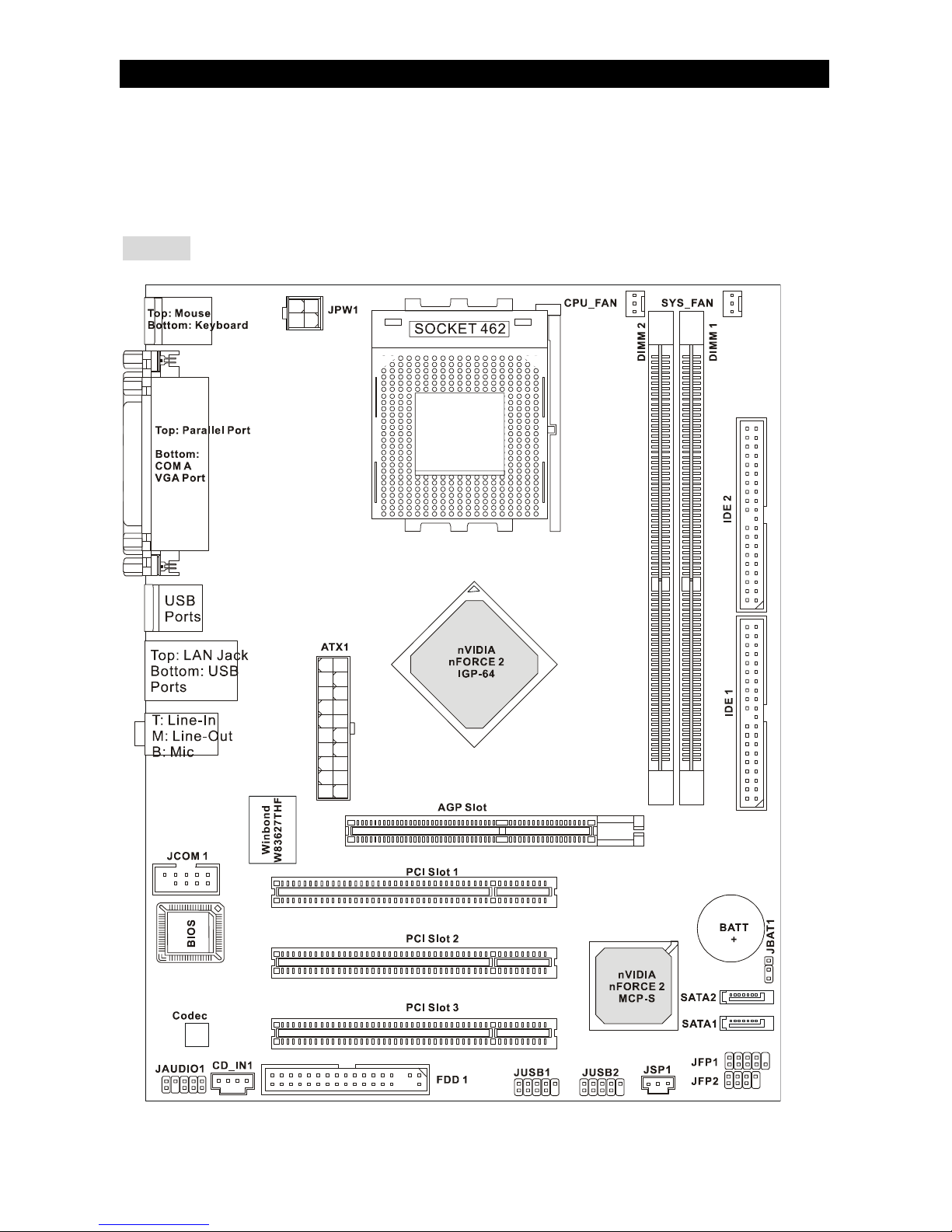
2. Insert the DIMM memory module vertically into the DIMM slot. Then push it in until the
golden finger on the memory module is deeply inserted in the socket.
3. The plastic clip at each side of the DIMM slot will automatically close.
Power Supply
The mainboard supports ATX power supply for the power system.
Before inserting the power supply connector, always make sure
that all components are installed properly to ensure that no damage
will be caused. A 300W or above power supply is suggested.
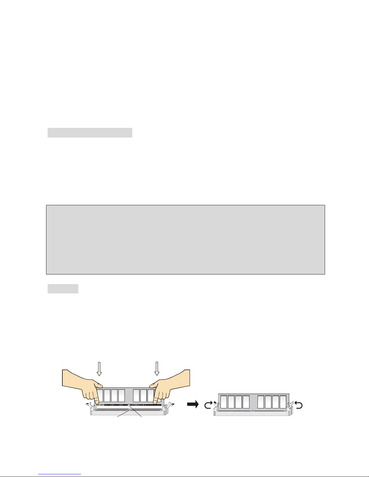
ATX 20-Pin Power Connector: ATX1
This connector allows you to connect to an ATX power supply. To
connect to theATX power supply, make sure the plug of the power supply is inserted in the
proper orientation and the pins are aligned. Then push down the power supply firmly into the
connector.
ATX 12V Power Connector: JPW1
This 12V power connector is used to provide power to the CPU.
Floppy Disk Drive Connector: FDD1
The mainboard provides a standard floppy disk drive
connector that supports 360K, 720K, 1.2M, 1.44M and
2.88M floppy disk types.
IDE Connectors: IDE1/IDE2
The mainboard has a 32-bit Enhanced PCI IDE and Ultra
DMA 66/100/133 controller that provides PIO mode 0~4,
Bus Master, and Ultra DMA 33/66/100/133 function. You can connect up to four hard disk drives,
CD-ROM, 120MB Floppy and other devices.
The first hard drive should always be connected to IDE1. IDE1 can connect a Master and a Slave
drive. You must configure second hard drive to Slave mode by setting the jumper accordingly.
IDE2 can also connect a Master and a Slave drive.
MSI Reminds You...
If you install two hard disks on cable, you must configure the second drive to Slave mode by
setting its jumper. Refer to the hard disk documentation supplied by hard disk vendors for jumper
setting instructions.
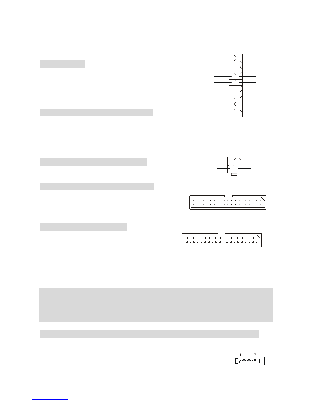
Serial ATA Connectors controlled by nVIDIA MCP2SL: SATA1, SATA2
The Southbridge of this mainboard is nVIDIA MCP2SL, which supports two serial connectors
SATA1 & SATA2.
SATA1 & SATA2 are dual high-speed Serial ATA interface ports. Each supports
1st generation serial ATA data rates of 150 MB/s. Both connectors are fully
11
3.3V3.3V
-12V
GND
PW_O
K
5V_SB
12V
PS_ON
2
0
1
1
0
GND
GND
GND
-5V
5V
5V
3.3V
GND
5V
GND
GND
5V
12
3
4
GND
12V
GND
12V

7
compliant with Serial ATA 1.0 specifications. Each Serial ATA connector can connect to 1 hard
disk device.
MSI Reminds You...
Please do not fold the serial ATA cable in a 90-degree angle, which will cause the loss of data
during transmission.
CD-In Connector: CD_IN1
The connector is for CD-ROM audio connector.
Fan Power Connectors: CPU_FAN/SYS_FAN
The CPU_FAN (processor fan) and SYS_FAN (system fan) support system
cooling fan with +12V. They support three-pin head connector. When
connecting the wire to the connectors, always take note that the red wire is the
positive and should be connected to the +12V, the black wire is Ground and should be connected
to GND. If the mainboard has a System Hardware Monitor chipset on-board, you must use a
specially designed fan with speed sensor to take advantage of the CPU fan control.
MSI Reminds You...
Always consult the vendors for proper CPU cooling fan.
Front Panel Connectors: JFP1/JFP2
The mainboard provides two front panel connectors for
electrical connection to the front panel switches and
LEDs. JFP1 is compliant with Intel Front Panel I/O
Connectivity Design Guide.
Front Panel Audio Connector: JAUD1
The front panel audio connector allows you to connect to the front panel audio and is compliant
with Intel ® Front Panel I/O Connectivity Design Guide.
MSI Reminds You...
If you do not want to connect to the front audio header, pins 5 & 6, 9 & 10 have to be jumpered in
order to have signal output directed to the rear audio ports. Otherwise, the Line-Out connector on
the back panel will not function.
1
2
9
10
HDD
LED
Power
LED
Power
LED
Speaker
Reset
Switch
Power
Switch
11
7
9
22
8
10
JFP1 JFP2

8
Front USB Connector: JUSB1/JUSB2
The mainboard provides two standard USB 2.0 pin headers
JUSB1&JUSB2. USB2.0 technology increases data transfer rate
up to a maximum throughput of 480Mbps, which is 40 times
faster than USB 1.1, and is ideal for connecting high-speed USB
interface peripherals such as USB HDD, digital cameras, MP3 players, printers, modems and the
like.
MSI Reminds You...
Please note that the pins of VCC & GND must be connected correctly, or it may cause some
damage
SPDIF-Out Connector: JSP1
This connector is used to connect SPDIF (Sony & Philips Digital Interconnect
Format) interface for digital audio transmission.
Serial Port Connector: JCOM1 (Optional)
The mainboard offers one 9-pin male DIN connector COM A (on the rear
panel), and one optional serial port JCOM1. Both are 16550A high speed
communication ports that send/receive/ 16 bytes FIFOs. You can attach a
serial mouse or other serial device directly to them.
Clear CMOS Jumper: JBAT1
There is a CMOS RAM on board that has a power supply
from external battery to keep the data of system
configuration. With the CMOS RAM, the system can
automatically boot OS every time it is turned on. If you want
to clear the system configuration, use the JBAT1 (Clear CMOS Jumper) to clear data. Follow the
instructions in the image to clear the data.
MSI Reminds You...
You can clear CMOS by shorting 2-3 pin while the system is off. Then return to 1-2 pin position.
Avoid clearing the CMOS while the system is on; it will damage the mainboard.
AGP (Accelerated Graphics Port) Slot
The AGP slot allows you to insert the AGP
graphics card.AGP is an interface specification
designed for the throughput demands of 3D
graphics. It introduces a 66MHz, 32-bit channel for the graphics controller to directly access main
memory. The mainboard supports 4X/8X AGP card.
PCI (Peripheral Component Interconnect) Slots
The PCI slots allow you to insert the expansion cards
to meet your needs. When adding or removing
expansion cards, make sure that you unplug the power supply first. Meanwhile, read the

9
documentation for the expansion card to make any necessary hardware or software settings for
the expansion card, such as jumpers, switches or BIOS configuration.
PCI Interrupt Request Routing
The IRQ, abbreviation of interrupt request line and pronounced I-R-Q, are hardware lines over
which devices can send interrupt signals to the microprocessor. The PCI IRQ pins are typically
connected to the PCI bus INT A# ~ INT D# pins as follows:
Order1 Order2 Order3 Order4
PCI Slot 1 INT C# INT D# INT A# INT C#
PCI Slot 2 INT D# INT A# INT B# INT B#
PCI Slot 3 INT A# INT B# INT C# INT D#

10
BIOS Setup
Power on the computer and the system will start POST (Power On Self Test) process. When the
message below appears on the screen, press <DEL> key to enter Setup.
DEL: Setup F7: Setup Defaults F10: Save & Exit TAB: Logo
If the message disappears before you respond and you still wish to enter Setup, restart the
system by turning it OFF and On or pressing the RESET button. You may also restart the system
by simultaneously pressing <Ctrl>, <Alt>, and <Delete> keys.
Main Page
Standard CMOS Features
Use this menu for basic system configurations, such as time, date etc.
Advanced BIOS Features
Use this menu to setup the items of Award special enhanced features.
Advanced Chipset Features
Use this menu to change the values in the chipset registers and optimize your system
performance.
Integrated Peripherals
Use this menu to specify your settings for integrated peripherals.
Power Management Setup
Use this menu to specify your settings for power management.
PNP/PCI Configurations
This entry appears if your system supports PnP/PCI.
H/W Monitor
This entry shows your hardware & PC health status.
Cell Menu
Use this menu to specify your settings for frequency/voltage control.
Set Supervisor Password

11
Use this menu to set Supervisor Password.
Set User Password
Use this menu to set User Password.
Load Optimized Defaults
Use this menu to load the optimized default settings into the BIOS for the best system
performance operations.
Save & Exit Setup
Save changes to CMOS and exit setup.
Exit Without Saving
Abandon all changes and exit setup.

12
Cell Menu
High Performance Mode
This field allows you to select the DDR timing setting. Set to [Optimized] for the most stable
settings by SPD automatically. Setting to [High Performance] or [Turbo] will increase the system
performance but may have instability problems. Selecting [Manual] allows users to configure
these fields manually for the customized performance options, and it is recommend for experts
and power users only. Setting options: [Optimized], [High Performance], [Turbo], [Manual].
Adjust CPU FSB Frequency
This setting allows you to select the CPU Front Side Bus clock frequency. Settings:
[100MHz]~[300MHz] at 1MHz increment.

13
Load Optimized Default
You can load the BIOS optimized default values provided by the mainboard manufacturer for the
stable performance.
For the complete BIOS introduction and setup, please visit MSI website at
http://www.msi.com.tw.

14
MSI Special Features
PC Alert 4
The PC Alert 4 is a utility you can find in the CD-ROM disk. The
utility is just like your PC doctor that can detect the following PC
hardware status during real time operation:
* monitor CPU & system temperatures
* monitor fan speeds
* monitor system voltages
If one of the items above is abnormal, the program main screen will be immediately shown on the
screen, with the abnormal item highlighted in red. This will continue to be shown until the
condition returns to the normal status.
Users can use the Adjusting Keys to change the minimum and maximum threshold of each
item for the system to send out a warning message. Click Temperature to select the
temperature modes of either Fahrenheit (℉) or Celsius (℃). The PC Alert4 icon on the Status
Area will show the current CPU temperature.
To better protect the CPU from overheating, a new feature, COOLER XP, has been added to
decrease the temperature of AMD Athlon XP CPU. To do so, simply click COOLER XP and the
screen will show the Cute skin (as shown below) with information about the CPU and chipset.
Right-click the mouse to select the skin you want to switch to.
Please note that the new feature COOLER XP will work only if your mainboard supports AMD
Athlon XP CPU. Items shown on PC Alert 4 vary depending on your system’s status.
Adjusting Key
Temperature
mode
Cooler XP

15
Introduction
Félicitation vous venez d’acheter une carte mère M-ATX K7N2GM-V (MS-7119 v1.0). La
K7N2GM-V est basée sur les chipsets nVIDIA nForce2 IGP-64 & nVIDIA MCP2SL offrant un
système très performant. La carte fonctionne avec les processeurs AMD ® AthlonTM / AthlonTM
XP / DuronTM/ Sempron, la K7N2GM-V offre de hautes performances.
Schéma

16
Spécificités
CPU
zSupporte les processeurs Socket A (Socket-462) pour AMD®Athlon™/ Athlon
XP™/Duron™/ Sempron™
zSupporte jusqu’à 3200+ MHz ou plus, ne supporte pas les CPU en dessous de 1100 MHz
zSupporte FSB 333 MHz/400 MHz.
(http://www.msi.com.tw/program/products/mainboard/mbd/pro_mbd_cpu_support.php)
Chipset
zChipset nForce2 IGP-64
- FSB @400MHz.
- Supporte la mémoire DDR 266/333/400.
- AGP 4X/8X.
zChipset nForce MCP2SL
- Matériel audio intégré Sound Blaster/Direct Sound AC97.
- Contrôleur Ultra DMA 66/100/133 master mode PCI EIDE.
- Compatible avec la gestion d’énergieACPI & PC2001.
- Supporte jusqu’à 8 ports USB2.0.
-Faster Ethernet MAC intégré.
Mémoire Principale
zSupporte quatre banques de mémoire DDR 184 broches.
zSupporte un maximum de mémoire de 2GB (simple canal).
zSupporte DDR 2.6v.
zSupporte DDR400/333.
(Pour une mise à jour sur les modules de mémoire supportés, veuillez visiter
http://www.msi.com.tw/program/products/mainboard/mbd/pro_mbd_trp_list.php )
Slots
zUn slot AGP (Accelerated Graphics Port) 8X/4X
zTrois slots PCI 2.2 32-bit PCI bus (supportant l’interface PCI bus 3.3v/5v).
IDE Intégré
zUn contrôleur IDE sur le chipset nForce MCP2SL procure IDE HDD/CD-ROM avec PIO, Bus
Master et les modes opératoires Ultra DMA 66/100/133.
zPossibilité de connecter jusqu’à 4 matériels IDE
Périphériques Intégrés
Les périphériques intégrés sont :
- 1 port floppy supportant 2 FDD avec 360K, 720K, 1.2M, 1.44M et 2.88Mbytes.
- 1 port série, 1 port VGA , 1 port série optionnel JCOM1.
- 1port parallèle supportant les modes SPP/EPP/ECP.
This manual suits for next models
1
Table of contents
Other MSI Motherboard manuals

MSI
MSI MS-6533 User manual

MSI
MSI K8N SLI-F User manual

MSI
MSI X299 RAIDER User manual

MSI
MSI MS-CF02 User manual

MSI
MSI MAG B460M BAZOOKA User manual

MSI
MSI D3050 User manual

MSI
MSI B450 GAMING PRO CARBON AC User manual

MSI
MSI MS-98F5 User manual

MSI
MSI B85M GAMING User manual

MSI
MSI Z170A KRAIT GAMING Operator's manual

MSI
MSI MAG A520M VECTOR WIFI User manual

MSI
MSI G52-72381X1 User manual

MSI
MSI H170M PRO-DH User manual

MSI
MSI MS-7366 User manual

MSI
MSI PRO Z690-A WIFI DDR4 User manual

MSI
MSI P35 Neo Combo Series User manual

MSI
MSI MS-6337 User manual

MSI
MSI MS-6183 User manual

MSI
MSI A88X-G45 GAMING User manual

MSI
MSI H6M-P32/W8 series User manual