MSI MEG Series User manual

MEG Series
Motherboard
MEG Z790 ACE MAX
User Guide

2
English
Contents
Quick Start..................................................................................................................... 4
Specifications.............................................................................................................. 16
Special Features......................................................................................................... 22
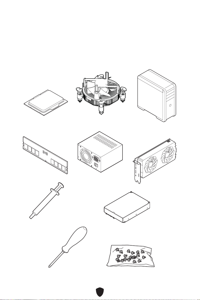
Package Contents ...................................................................................................... 23
Back Panel Connectors ............................................................................................. 24
LAN Port LED Status Table .................................................................................. 25
Audio Jacks Connection ....................................................................................... 26
Installing Antennas............................................................................................... 28
Connecting Thunderbolt Devices via Daisy-chain................................................ 29
Overview of Components........................................................................................... 30
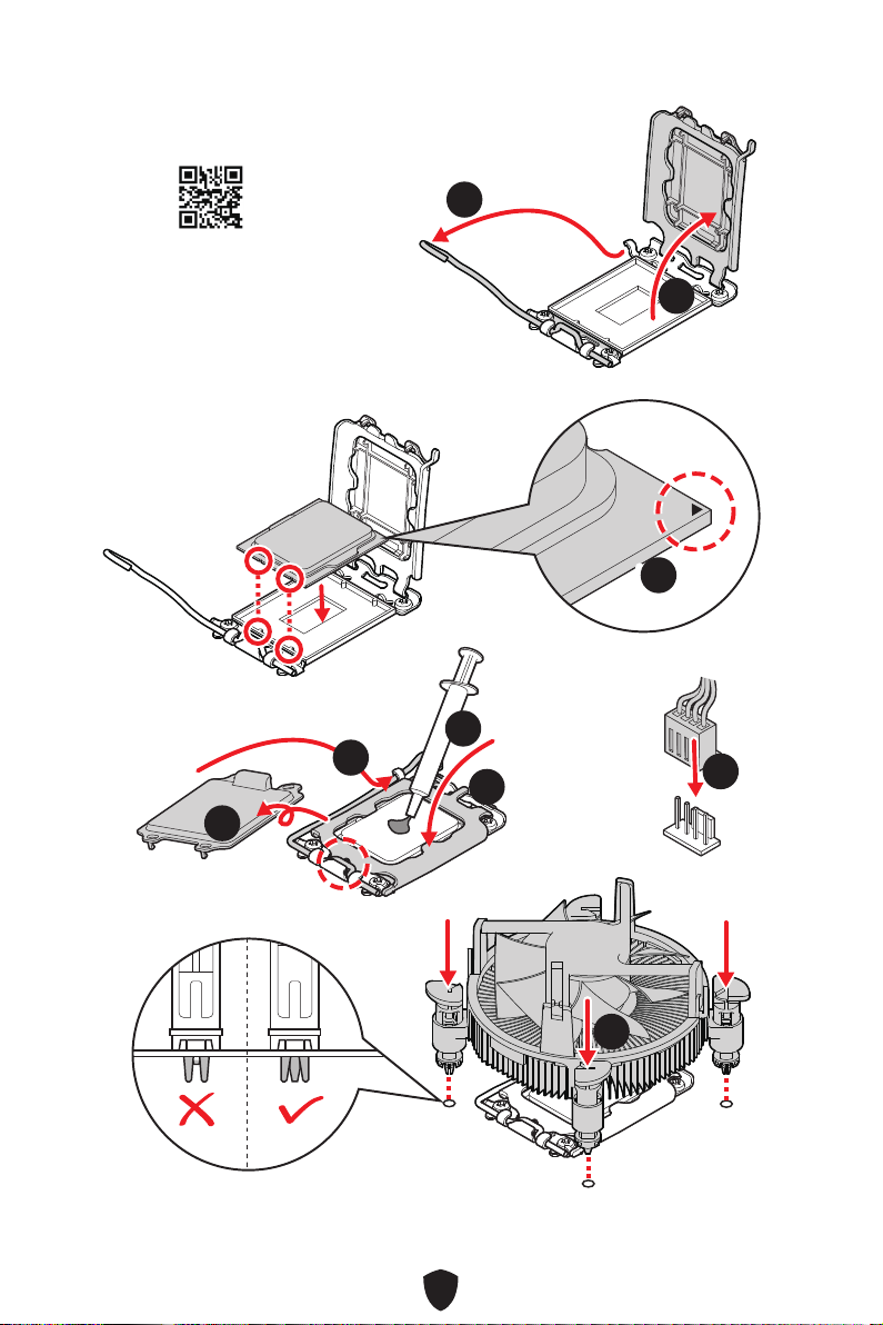
CPU Socket ........................................................................................................... 31
DIMM Slots............................................................................................................ 32
PCI_E1~3: PCIe Expansion Slots.......................................................................... 33
M2_1~5: M.2 Slots (Key M) ................................................................................... 34
SATA_5~8 & SATA_A1~A2: SATA 6Gb/s Connectors ........................................... 43
JAUD1: Front Audio Connector ............................................................................ 43
JFP1, JFP2: Front Panel Connectors................................................................... 44
JDASH1: Tuning Controller Connector ................................................................ 45
W_FLOW1: Water Flow Meter Connector ............................................................ 45
JCI1: Chassis Intrusion Connector....................................................................... 46
POWER1, RESET1: Power Button, Reset Button ................................................. 46
CPU_PWR1~2, ATX_PWR1, PD_PWR1: Power Connectors ................................ 47
JUSB5~6: USB 3.2 Gen 2x2 Type-C
Front Panel
Connectors............................... 48
JUSB3~4: USB 3.2 Gen 1 Connectors .................................................................. 48
JUSB1~2: USB 2.0 Connectors............................................................................. 49
JTPM1: TPM Module Connector........................................................................... 49
T_SEN1~2: Thermal Sensor Connector............................................................... 50
BIOS_SW1: Multi-BIOS Switch ............................................................................. 50
JOC_FS1: Safe Boot Jumper................................................................................ 51
JOC_RT1: OC Retry Button Connector................................................................. 51
JSLOW1: Slow Mode Booting Jumper.................................................................. 52
JLN1~2: Low Temperature Booting Jumpers ..................................................... 52
CPU_FAN1, PUMP_FAN1~2, SYS_FAN1~5: Fan Connectors.............................. 53

3
JBAT1: Clear CMOS (Reset BIOS) Jumper........................................................... 54
BAT1: CMOS Battery............................................................................................. 55
V-Check Points Lite .............................................................................................. 55
JAF_1: Integrated ARGB LED & System Fans Connector .................................. 56
JRGB1: RGB LED Connector ................................................................................ 57
JARGB_V2_1~3: A-RAINBOW V2 (ARGB Gen2) LED Connectors ........................ 58
Onboard LEDs............................................................................................................. 60
EZ Debug LED....................................................................................................... 60
LED_SW1: EZ LED Control................................................................................... 60
Debug Code LED................................................................................................... 61
Boot Phases.......................................................................................................... 61
Debug Code LED Table......................................................................................... 61
Installing OS, Drivers & MSI Center.......................................................................... 68
MSI Center............................................................................................................ 71
UEFI BIOS.................................................................................................................... 72
BIOS Setup............................................................................................................ 73
Resetting BIOS...................................................................................................... 74
Updating BIOS....................................................................................................... 74
Block Diagram............................................................................................................ 76
Regulatory Notices........................................................................................................ i

4
Quick Start
Thank you for purchasing a new motherboard from MSI®. This Quick Start section
provides demonstration diagrams about how to install your computer. Some of the
installations also provide video demonstrations. Please link to the URL to watch it
with the web browser on your phone or tablet. You may have even link to the URL by
scanning the QR code.
Preparing Tools and Components
Intel® LGA1700 CPU LGA1700 CPU Fan
Graphics Card
SATA Hard Disk Drive
Phillips Screwdriver
Chassis
Power Supply Unit
A Package of Screws
Thermal Paste
DDR5 Memory

5
Safety Information
∙The components included in this package are prone to damage from electrostatic
discharge (ESD). Please adhere to the following instructions to ensure successful
computer assembly.
∙Ensure that all components are securely connected. Loose connections may cause
the computer to not recognize a component or fail to start.
∙Hold the motherboard by the edges to avoid touching sensitive components.
∙It is recommended to wear an electrostatic discharge (ESD) wrist strap when
handling the motherboard to prevent electrostatic damage. If an ESD wrist strap
is not available, discharge yourself of static electricity by touching another metal
object before handling the motherboard.
∙Store the motherboard in an electrostatic shielding container or on an anti-static
pad whenever the motherboard is not installed.
∙Before turning on the computer, ensure that there are no loose screws or metal
components on the motherboard or anywhere within the computer case.
∙Do not boot the computer before installation is completed. This could cause
permanent damage to the components as well as injury to the user.
∙If you need help during any installation step, please consult a certified computer
technician.
∙Always turn off the power supply and unplug the power cord from the power outlet
before installing or removing any computer component.
∙Keep this user guide for future reference.
∙Keep this motherboard away from humidity.
∙Make sure that your electrical outlet provides the same voltage as is indicated on
the PSU, before connecting the PSU to the electrical outlet.
∙Place the power cord such a way that people can not step on it. Do not place
anything over the power cord.
∙All cautions and warnings on the motherboard should be noted.
∙If any of the following situations arises, get the motherboard checked by service
personnel:
• Liquid has penetrated into the computer.
• The motherboard has been exposed to moisture.
• The motherboard does not work well or you can not get it work according to user
guide.
• The motherboard has been dropped and damaged.
• The motherboard has obvious sign of breakage.
∙Do not leave this motherboard in an environment above 60°C (140°F), it may damage
the motherboard.

6
Case stand-off notification
To prevent damage to the motherboard, any unnecessary mounting stand-off between
the motherboard circuits and the computer case is prohibited. The Case standoff keep
out zone signs will be marked on the backside of motherboard (as shown below) to
serve as a warning to user.
Avoid collision notification
Protective paint is printed around each screw hole to prevent parts from being
scratched.

7
Installing a Processor
⚽
∙https://youtu.be/KMf9oIDsGes
11
22
33
66
44
5577
88
99

8
Installing DDR5 memory
∙https://youtu.be/XiNmkDNZcZk
⚽
DIMMA2 DIMMA2
DIMMB2
DIMMA1
DIMMA2
DIMMB1
DIMMB2

9
HDD LED
RESET SW
Connecting the Front Panel Header
∙http://youtu.be/DPELIdVNZUI
JFP1
HDD LED HDD LED -
HDD LED +
POWER LED -
POWER LED +
POWER LED
RESET SW
POWER SW
POWER LED+
POWER LED-
HDD LED
⚽
1
2 10
9
Power LED
Reserved
Power Switch
JFP1
Reset SwitchHDD LED

10
BAT1
Installing the Motherboard
11∙https://youtu.be/wWI6Qt51Wnc
⚽
Torque:
3 kgf·cm*
*3 kgf·cm
= 0.3 N·m
= 2.6 lbf·in
22

11
Connecting the Power Connectors
∙http://youtu.be/gkDYyR_83I4
ATX_PWR1
CPU_PWR1~2
⚽
PD_PWR1

12
Installing SATA Drives
∙http://youtu.be/RZsMpqxythc
11
2233
44
55
⚽

13
Installing a Graphics Card
∙http://youtu.be/mG0GZpr9w_A
⚽
11
22
33
44
55
66

14
Connecting Peripheral Devices

15
Power On
44
33
1122

16
Specifications
CPU
∙Supports 12th/ 13th Gen Intel® Core™ Processors,
Pentium® Gold and Celeron® Processors*
∙Processor socket LGA1700
* Please go to www.msi.com to get the newest support status as new processors
are released.
Chipset Intel® Z790 Chipset
Memory
∙4x DDR5 memory slots, support up to 192GB*
∙Supports 1R 5600 MHz (by JEDEC & POR)
∙Max. overclocking frequency:
• 1DPC 1R Max speed up to 7800+ MHz
• 1DPC 2R Max speed up to 6800+ MHz
• 2DPC 1R Max speed up to 6400+ MHz
• 2DPC 2R Max speed up to 6000+ MHz
∙DIMM slots with single-sided latches
∙Supports Intel® XMP 3.0 OC
∙Supports Dual-Controller Dual-Channel mode
∙Supports non-ECC, un-buffered memory
* Please refer to www.msi.com for more information on compatible memory.
Expansion Slots
∙3x PCIe x16 slots
• Supports x16/x0, x8/x8
• PCI_E1 slot* (From CPU)
• Supports up to PCIe 5.0 x16
• PCI_E2 slot** (From CPU)
• Supports up to PCIe 5.0 x8
• PCI_E3 slot (From Z790 Chipset)
• Supports up to PCIe 4.0 x4
* PCI_E1 slot will run at PCIe 5.0 x8 mode when installing device in the PCI_E2
slot or M2_4 slot.
** M2_4 slot will be unavailable when installing device in the PCI_E2 slot.
Onboard Graphics
∙1x DisplayPort over USB-C port, supporting a maximum
resolution of 4K 60Hz*/**
* Available only on processors featuring integrated graphics.
** Graphics specifications may vary depending on the CPU installed.
Multi-GPU Supports AMD Multi-GPU
Continued on next column

17
Continued from previous column
Thunderbolt 4
Intel® JHL8540 Thunderbolt™ 4 Controller
∙2x Thunderbolt™ 4 (USB-C) ports on the back panel
• Supports up to 40Gbps transfer rate with Thunderbolt
devices
• Supports up to 20Gbps transfer rate with USB4 devices
• Supports up to 10Gbps transfer rate with USB 3.2
devices
• Supports up to 5V/3A ,15W power charging
• Each port can daisy-chain up to three Thunderbolt 4
devices or five Thunderbolt 3 devices
• Supports up to 8K display (need to connect the
DisplayPort of the motherboard or discrete graphics
card to the Mini DisplayPort Input port on the back
panel)
SATA Ports
∙6x SATA 6Gb/s ports
• SATA_5~8* (From Z790 chipset)
• SATA_A1~A2 (From ASM1061)
* SATA_7 will be unavailable when installing M.2 SATA SSD in the M2_5 slot.
Continued on next column

18
Continued from previous column
M.2 SSD Slots
∙5x M.2 slots (Key M)
• M2_1 slot (From CPU)
• Supports up to PCIe 4.0 x4
• Supports 2260/ 2280/ 22110 storage devices
• M2_2 slot (From Z790 chipset)
• Supports up to PCIe 4.0 x4
• Supports 2260/ 2280 storage devices
• M2_3 slot (From Z790 chipset)
• Supports up to PCIe 4.0 x4
• Supports up to SATA 6Gb/s
• Supports 2260/ 2280 storage devices
• M2_4 slot* (From CPU)
• Supports up to PCIe 5.0 x4
• Supports 2280 storage devices
• M2_5 slot** (From Z790 chipset)
• Supports up to PCIe 4.0 x4
• Supports up to SATA 6Gb/s
• Supports 2260/ 2280/ 22110 storage devices
* M2_4 slot will be unavailable when installing device in the PCI_E2 slot.
** SATA_7 will be unavailable when installing M.2 SATA SSD in the M2_5 slot.
RAID
∙Supports RAID 0, RAID 1, RAID 5 and RAID 10 for SATA
storage devices*
∙Supports RAID 0, RAID 1, RAID 5 and RAID 10 for M.2
NVMe storage devices
* SATA_A1_A2 do not support RAID function.
Audio
Realtek® ALC4082 Codec + ES9280AQ PRO Combo DAC/HPA
∙7.1-Channel USB High Performance Audio
∙Supports up to 32-bit/384kHz playback on front panel
∙Supports S/PDIF output
LAN ∙2x Intel® 2.5Gbps LAN controllers
Continued on next column

19
Continued from previous column
Wi-Fi & Bluetooth®
Wi-Fi 7
∙ The Wireless module is pre-installed in the M.2 (Key-E)
slot
∙ Supports MU-MIMO TX/RX, 2.4GHz/ 5GHz/ 6GHz*(320MHz)
up to 5.8Gbps
∙ Supports 802.11 a/ b/ g/ n/ ac/ ax/ be
∙ Supports Bluetooth® 5.4**, MLO, 4KQAM
*6GHz band support may depend on every country’s regulations and Wi-Fi 7 will
be ready in Windows 11 SV3.
** The Bluetooth version may be updated. Please refer to the Wi-Fi chipset
vendor’s website for details. Bluetooth 5.4 support schedule depends on MSFT
Windows 11 plan.
Power Connectors
∙1x 24-pin ATX main power connector
∙2x 8-pin ATX 12V power connectors
∙1x 6-pin PD power connector*
* To achieve USB PD 60W charging for JUSB6, PD_PWR1 connector needs to be
connected to the power supply unit.
Internal USB
Connectors
∙2x USB 3.2 Gen 2x2 20Gbps Type-C front panel
connectors* (From Z790 chipset)
• JUSB6 supports USB PD 60W fast charging
∙2x USB 3.2 Gen 1 5Gbps connectors (From Hub GL3523)
• Supports additional 4 USB 3.2 Gen 1 5Gbps ports
∙2x USB 2.0 Type-A connectors (From Hub GL850G)
• Supports additional 4 USB 2.0 ports
* To achieve 60W PD fast charging for JUSB6, the PD_PWR1 connector needs to
be connected to the power supply unit.
Fan Connectors
∙1x 4-pin CPU fan connector
∙2x 4-pin water-pump fan connectors
∙5x 4-pin system fan connectors
System Connectors
∙1x Front panel audio connector
∙2x System panel connectors
∙1x Chassis Intrusion connector
∙1x 3-pin Water Flow connector
∙1x TPM module connector
∙1x Tuning Controller connector
Continued on next column

20
Continued from previous column
Buttons ∙1x Power button
∙1x Reset button
Jumpers
∙1x Clear CMOS jumper
∙1x OC safe boot jumper
∙1x Slow mode jumper
∙2x Low temperature booting jumpers
Switches ∙1x EZ LED Control switch
∙1x Multi-BIOS switch
LED Features
∙1x 4-pin RGB LED connector
∙3x 3-pin ARGB Gen2 LED connectors
∙4x EZ Debug LED
∙1x 2-Digit Debug Code LED
∙1x Integrated ARGB LED & system fan connector
Back Panel
Connectors
∙1x Clear CMOS button
∙1x Flash BIOS button
∙1x Smart button
∙2x LAN (RJ45) ports
∙3x USB 3.2 Gen 2 10Gbps Type-A ports (From Z790
chipset)
∙4x USB 3.2 Gen 2 10Gbps Type-A ports (From Hub-
GL3590)
∙1x USB 3.2 Gen 2 10Gbps Type-C port (From Z790 chipset)
with DisplayPort Alt Mode
∙2x Thunderbolt 4 USB-C ports
∙2x Mini DisplayPort Inputs (for Thunderbolt 4 pass
through)
∙2x Wi-Fi Antenna connectors
∙5x OFC audio jacks
∙1x Optical S/PDIF Out connector
I/O Controller NUVOTON NCT6687D-R Controller Chip
Continued on next column
Other manuals for MEG Series
1
This manual suits for next models
1
Table of contents
Other MSI Motherboard manuals

MSI
MSI Z77IA-E53 series User manual

MSI
MSI MS-6728 User manual

MSI
MSI MS-6380LE User manual

MSI
MSI MICRO ATX EX7 User manual

MSI
MSI MAG B760 TOMAHAWK WIFI User manual

MSI
MSI G41M-P25 User manual

MSI
MSI PRO Z790-P WIFI DDR4 User manual

MSI
MSI MS-CF06 User manual

MSI
MSI MEG Z590 ACE User manual

MSI
MSI Z490-A PRO User manual

MSI
MSI K7T TURBO2 - K7T Turbo 2 Motherboard User manual

MSI
MSI B250I PRO User manual

MSI
MSI MS-6577 User manual

MSI
MSI MS-6378 User manual

MSI
MSI MAG B560M BAZOOKA User manual

MSI
MSI MS-6534 User manual

MSI
MSI KT6-V User manual

MSI
MSI MS-6378 Instruction manual

MSI
MSI 650GLMS User manual

MSI
MSI PRO B760M-A WIFI DDR4 User manual