MSI MS-6380E User manual

i
MSI
Version 1.2
G52-MA00636
MS-6380E (v1.X) ATX Mainboard
K7T266 Pro2-A
MICRO-STAR INTERNATIONAL
Downloaded from www.Manualslib.com manuals search engine

ii
Manual Rev: 1.2
Release Date: May 2002
FCC-B Radio Frequency Interference Statement
This equipment has been tested and found to comply with the limits for a class
B digital device, pursuant to part 15 of the FCC rules. These limits are designed
to provide reasonable protection against harmful interference when the equip-
ment is operated in a commercial environment. This equipment generates, uses
and can radiate radio frequency energy and, if not installed and used in accor-
dance with the instruction manual, may cause harmful interference to radio
communications. Operation of this equipment in a residential area is likely to
cause harmful interference, in which case the user will be required to correct
the interference at his own expense.
Notice 1
The changes or modifications not expressly approved by the party respon-
sible for compliance could void the users authority to operate the equipment.
Notice 2
Shielded interface cables and A.C. power cord, if any, must be used in order to
comply with the emission limits.
VOIR LA NOTICE DINSTALLATION AVANT DE RACCORDER AU
RESEAU.
Micro-Star International MS-6380E
Tested to comply
with FCC Standard
For Home or Office Use
Downloaded from www.Manualslib.com manuals search engine

iii
Edition
May 2002
Copyright Notice
The material in this document is the intellectual property of MICRO-STAR
INTERNATIONAL. We take every care in the preparation of this document,
but no guarantee is given as to the correctness of its contents. Our products
are under continual improvement and we reserve the right to make changes
without notice.
Trademarks
All trademarks are the properties of their respective owners.
AMD, Athlon and Duron are registered trademarks of AMD Corporation.
PS/2 and OS®/2 are registered trademarks of International Business Machines
Corporation.
Windows®98/2000/NT/ME/XP are registered trademarks of Microsoft
Corporation.
Netware®is a registered trademark of Novell, Inc.
Award®is a registered trademark of Phoenix Technologies Ltd.
AMI®is a registered trademark of American Megatrends Inc.
Revision History
Revision Revision History Date
1.2 Adopt KT266A & 8233A, May 2002
2Ch AC97 S/W audio,
No USB 2.0 & IDE RAID
Downloaded from www.Manualslib.com manuals search engine

iv
1. Always read the safety instructions carefully.
2. Keep this Users Manual for future reference.
3. Keep this equipment away from humidity.
4. Lay this equipment on a reliable flat surface before setting it up.
5. The openings on the enclosure are for air convection hence protects the
equipment from overheating. DO NOT COVER THE OPENINGS.
6. Make sure the voltage of the power source and adjust properly 110/220V
before connecting the equipment to the power inlet.
7. Place the power cord such a way that people can not step on it. Do not
place anything over the power cord.
8. Always Unplug the Power Cord before inserting any add-on card or module.
9. All cautions and warnings on the equipment should be noted.
10. Never pour any liquid into the opening that could damage or cause electri-
cal shock.
11. If any of the following situations arises, get the equipment checked by a
service personnel:
lThe power cord or plug is damaged
lLiquid has penetrated into the equipment
lThe equipment has been exposed to moisture
lThe equipment has not work well or you can not get it work according
to Users Manual.
lThe equipment has dropped and damaged
lIf the equipment has obvious sign of breakage
12. DO NOT LEAVE THIS EQUIPMENT IN AN ENVIRONMENT
UNCONDITIONED,STORAGETEMPERATUREABOVE600 C(1400F),IT
MAY DAMAGE THE EQUIPMENT.
Safety Instructions
CAUTION: Danger of explosion if battery is incorrectly replaced.
Replace only with the same or equivalent type recommended by the
manufacturer.
Downloaded from www.Manualslib.com manuals search engine

v
CONTENTS
Chapter 1. Getting Started ........................................................................ 1-1
Mainboard Specification ...................................................................... 1-2
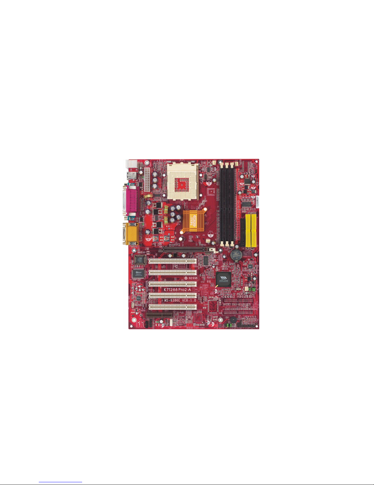
Mainboard Layout ............................................................................... 1-4
Quick Components Guide .................................................................... 1-5
MSI Special Features ........................................................................... 1-6
PC Alert III ................................................................................. 1-6
Fuzzy Logic 4 ............................................................................. 1-7
D-Bracket (Optional) .................................................................. 1-8
LiveBIOS/LiveDriver .......................................................... 1-10
Chapter 2. Hardware Setup ....................................................................... 2-1
Central Processing Unit: CPU .............................................................. 2-2
CPU Installation Procedures ......................................................... 2-2
Thermal Issue for CPU .................................................................. 2-3
CPU Core Speed Derivation Procedure ......................................... 2-4
CPU Clock Frequency Selection through BIOS ............................. 2-4
Memory ................................................................................................ 2-5
Introduction to DDR SDRAM ....................................................... 2-5
DIMM Module Combination......................................................... 2-6
Installing DDR Modules ............................................................... 2-6
Power Supply ....................................................................................... 2-7
ATX 20-Pin Power Connector: JWR1 ............................................ 2-7
Back Panel ............................................................................................ 2-8
Mouse Connector: JKBMS1 ......................................................... 2-8
Keyboard Connector: JKBMS1 ..................................................... 2-9
USB Connectors: USB1 ................................................................. 2-9
Serial Port Connectors: COM A & COM B.................................. 2-10
Joystick/Midi Connector ............................................................. 2-10
Parallel Port Connector: LPT1 ...................................................... 2-11
Audio Port Connectors ............................................................... 2-12
Downloaded from www.Manualslib.com manuals search engine

vi
Connectors ......................................................................................... 2-13
Floppy Disk Drive Connector: FDD1........................................... 2-13
Hard Disk Connectors: IDE1 & IDE2 ........................................... 2-14
Fan Power Connectors: CFAN1/SFAN1/PSFAN1/NBFAN1 ........ 2-15
IrDA Infrared Module Header: JIR1 ............................................ 2-16
Chassis Intrusion Switch Connector: J3 ...................................... 2-16
Front Panel Connectors: JFP1 & JFP2 ......................................... 2-17
Front Panel Audio Connector: JAUD1 ........................................ 2-18
Wake On Ring Connector: JMDM1 ............................................. 2-19
CD-In Connector: JCD ................................................................. 2-19
USB Front Panel Connector: JUSB2 ............................................ 2-20
D-Bracket Connector: JLED ..................................................... 2-21
Jumpers .............................................................................................. 2-22
Clear CMOS Jumper: JBAT1 ........................................................ 2-22
Slots ................................................................................................... 2-23
AGP (Accelerated Graphics Port) Slot ......................................... 2-23
PCI Slots ...................................................................................... 2-23
CNR (Communication Network Riser) Slot .................................. 2-23
PCI Interrupt Request Routing .................................................... 2-24
Chapter 3. BIOS Setup .............................................................................. 3-1
Entering Setup...................................................................................... 3-2
Selecting the First Boot Device ..................................................... 3-2
Control Keys ................................................................................. 3-3
Getting Help .................................................................................. 3-3
The Main Menu ................................................................................... 3-4
Standard CMOS Features .................................................................... 3-6
Advanced BIOS Features .................................................................... 3-8
Advanced Chipset Features............................................................... 3-13
Power Management Features ............................................................. 3-18
Downloaded from www.Manualslib.com manuals search engine

vii
PNP/PCI Configurations..................................................................... 3-22
Integrated Peripherals ........................................................................ 3-24
PC Health Status ................................................................................ 3-27
Frequency/Voltage Control ................................................................ 3-28
Set Supervisor/User Password ........................................................... 3-30
Load High Performance/BIOS Setup Defaults.................................... 3-31
Glossary .................................................................................................... G-1
Downloaded from www.Manualslib.com manuals search engine

Getting Started
1-1
Chapter 1. Getting Started
Thank you for purchasing the K7T266 Pro2-A (MS-6380E v1.X) ATX
motherboard. The K7T266 Pro2-A is a superior computer mainboard based
on VIA®Apollo KT266A (VT8366A & VT8233A) chipsets for optimal
system performance. Designed to fit the advanced AMD®Athlon,
Athlon XP or Duron (PGA) processor in the 462 pin package, the
K7T266 Pro2-A delivers a high performance and professional desktop
platform solution.
1
Getting Started
TOPICS
Mainboard Specification 1-2
Mainboard Layout 1-4
Quick Components Guide 1-5
MSI Special Features 1-6
Downloaded from www.Manualslib.com manuals search engine

Chapter 1
1-2
CPU
Supports Socket A (Socket-462) for AMD®Athlon/Athlon XP /Duron
processor
Supports 800MHz up to 1.8GHz (Athlon XP 2200+) processor
Chipset
VIA®VT8366A chipset
-FSB@200/266MHz
- AGP 4X and PCI Advanced high performance memory controller
VIA®VT8233A chipset
- High Bandwidth V-link Client controller
- Integrated Faster Ethernet LPC
- Integrated Hardware Sound Blaster/Direct Sound AC97 audio
- Ultra DMA 33/66/100/133 master mode PCI EIDE controller
- ACPI
Clock Generator
100/133MHz clocks are supported
MainMemory
Supports six memory banks using three 184-pin DDR DIMMs
Supports a maximum memory size up to 3GB
Supports 2.5V DDR SDRAM DIMM
Slots
One AGP slot
- AGP (Accelerated Graphics Port) specification compliant
- Supports AGP 2.0 1x/2x/4x
Five 32-bit PCI bus slots (support 3.3v/5v PCI bus interface)
One CNR (Communication Network Riser) slot
On-BoardIDE
An IDE controller on the VT8233A chipset provides IDE HDD/CD-ROM
with PIO, Bus Master and Ultra DMA133/100/66/33 operation modes
Can connect up to four IDE devices
Mainboard Specification
Downloaded from www.Manualslib.com manuals search engine

Getting Started
1-3
On-Board Peripherals
On-Board Peripherals include:
- 1 floppy port supports 2 FDDs with 360K, 720K, 1.2M, 1.44M and
2.88Mbytes
- 2 serial ports (COM A + COM B)
- 1 parallel port supports SPP/EPP/ECP mode
- 1 IrDA connector for SIR/ASKIR/HPSIR
- 1 audio/game port
- 1 D-Bracket pinheader
USB Interface
Supports USB 1.1
Audio
2 Channel AC97 S/W audio
BIOS
The mainboard BIOS provides Plug & Play BIOS which detects the pe-
ripheral devices and expansion cards of the board automatically.
The mainboard provides a Desktop Management Interface (DMI) function
which records your mainboard specifications.
Dimension
ATX Form Factor: 30.4 cm (L) x 23.5 cm (W)
Mounting
6 mounting holes
Downloaded from www.Manualslib.com manuals search engine

Chapter 1
1-4
Mainboard Layout
K7T266 Pro2-A (MS-6380E v1.X) ATX Mainboard
BATT
+
VT8233A
VIA
VT8366A
DDR1
DDR2
DDR3
J3
ATX
Power Supply
JUSB2
JAUD1
SOCKET 462
BIOS
PCI Slot 5
PCI Slot 4
PCI Slot 3
PCI Slot 2
PCI Slot 1
IDE1
IDE2
CNR
JBAT1
JLED
JFP2JFP1
JMDM1
JIR1
USB
ports
To p : Pa ra l l e l P o r t
Bottom:
COM A
COM B
Top : mouse
Bottom: keyboard CFAN1
NBFAN1
PSFAN1
SFAN1
Winbond
W83697HF
Codec
JCD
To p :
Game port
Bottom:
Line-Out
Line-In
Mic
FDD1
AGP Slot
Downloaded from www.Manualslib.com manuals search engine

Getting Started
1-5
Quick Components Guide
Component Function Reference
JWR1 ATX 20-pin power connector See p. 2-7
JKBMS1 Mouse connector See p. 2-8
JKBMS1 Keyboard connector See p. 2-9
USB1 USB connectors See p. 2-9
COM A & COM B Serial port connectors See p. 2-10
LPT1 Parallel port connector See p. 2-11
Audio port connectors Connecting to audio devices See p. 2-12
FDD1 Floppy disk drive connector See p. 2-13
IDE1~ IDE2 Hard disk connectors See p. 2-14
CFAN1/SFAN1/PSFAN1/ Fan power connectors See p. 2-15
NBFAN1
JIR1 IrDA infrared module connector See p. 2-16
J3 Chassis intrusion switch See p. 2-16
JFP1 & JFP2 Front panel connectors See p. 2-17
JAUD1 Front panel audio connector See p. 2-18
JMDM1 Wake on ring connector See p. 2-19
JCD CD-In connector See p. 2-19
JUSB2 Front USB connector See p. 2-20
JLED D-Bracket connector See p. 2-21
JBAT1 Clear CMOS jumper See p. 2-22
Downloaded from www.Manualslib.com manuals search engine

Chapter 1
1-6
PC Alert III
The PC AlertTM III is a utility you can find in the CD-ROM disk. The
utility is just like your PC doctor that can de-
tect the following PC hardware status during
real time operation:
* monitor CPU & system temperatures
* monitor fan speed(s)
* monitor system voltage
* monitor chassis intrusion
If one of the items above is abnormal,
the program main screen will be immediately
shown on the screen, with the abnormal item
highlighted in red. This will continue to be
shown until user disables the warning.
Note: Items shown on PC Alert III vary depending on your systems
status.
MSI Special Features
Downloaded from www.Manualslib.com manuals search engine

Getting Started
1-7
The Fuzzy Logic 4 utility is a user friendly tool that allows users to
view and adjust the current system status. To overclock the CPU FSB (Front
Side Bus) frequency under the Windows operating system, click FSB and use
the right and left arrow keys to select the desired FSB, and then click Apply to
apply the new setup value. To enable the system running at the specified FSB
every time when you click Turbo, click Save to save the desired FSB first. If
you want to know the maximal CPU overclocking value, click Auto to start
testing. The CPU FSB will automatically increase the testing value until the PC
reboots. After rebooting, click Turbo to apply the test result. Click Default to
restore the default values.
Features:
lMSI Logo links to the MSI Web site
lCPU Speed allows users to adjust the CPU speed through CPU
Multiplier and FSB
lVoltage allows user to adjust the voltage of CPU/Memory/AGP
lMSI Info provides information about the mainboard, BIOS and OS
lCPU Info provides detailed information about the CPU
lCPU Fan Speed shows the current running speed of CPU Fan
lCPU Temp. shows the current CPU temperature
Note: To adjust the options under CPU Speed and Voltage, use the
right and left arrow keys to select the desired value and then click
Apply to run the setup value.
Fuzzy Logic
4
Downloaded from www.Manualslib.com manuals search engine

Chapter 1
1-8
D-Bracket (optional)
D-Bracket is an external USB bracket integrating four Diagnostic LEDs,
which use graphic signal display to help users understand their system. The
LEDs provide up to 16 combinations of signals to debug the system. The 4
LEDs can debug all problems that fail the system, such as VGA, RAM or other
failures. This special feature is very useful for the overclocking users. These
users can use the feature to detect if there are any problems or failures.
Red Green
D-Bracket
D-Bracket Description
System Power ON
- The D-LED will hang here if the processor is damaged or
not installed properly.
Early Chipset Initialization
Memory Detection Test
- Testing onboard memory size. The D-LED will hang if
the memory module is damaged or not installed properly.
Decompressing BIOS image to RAM for fast booting.
Initializing Keyboard Controller.
Testing VGA BIOS
- This will start writing VGA sign-on message to the screen.
1 2
3 4
Downloaded from www.Manualslib.com manuals search engine

Getting Started
1-9
D-Bracket Description
Processor Initialization
- This will show information regarding the processor (like
brand name, system bus, etc)
Testing RTC (Real Time Clock)
Initializing Video Interface
- This will start detecting CPU clock, checking type of video
onboard. Then, detect and initialize the video adapter.
BIOS Sign On
- This will start showing information about logo, processor
brand name, etc.
Testing Base and Extended Memory
- Testing base memory from 240K to 640K and extended
memory above 1MB using various patterns.
Assign Resources to all ISA.
Initializing Hard Drive Controller
- This will initialize IDE drive and controller.
Initializing Floppy Drive Controller
- This will initializing Floppy Drive and controller.
Boot Attempt
- This will set low stack and boot via INT 19h.
Operating System Booting
1 2
3 4
Downloaded from www.Manualslib.com manuals search engine

Chapter 1
1-10
Live BIOS/Live Driver
The Live BIOS/Live Driver is a tool used to detect
and update your BIOS/drivers online so that you dont need
to search for the correct BIOS/driver version throughout the
whole Web site. To use the function, you need to install the
MSI Live Update Series 2 application. After the installation,
the MSI Live Update Series 2 icon (as shown on the right)
will appear on the screen.
Double click the MSI Live Update Series 2 icon, and the following
screen will appear:
Five buttons are placed on the leftmost pane of the screen. Click the desired
button to start the update process.
ll
ll
lLive BIOS Updates the BIOS online.
ll
ll
lLive Driver Updates the drivers online.
ll
ll
lLive VGA BIOS Updates the VGA BIOS online.
ll
ll
lLive VGA Driver Updates the VGA driver online.
ll
ll
lLive Utility Updates the utilities online.
If the product you purchased does not support any of the functions listed
above, a sorry message is displayed. For more information on the update
instructions, insert the companion CD and refer to the Live Update Series
Guide under the Manual Tab.
Downloaded from www.Manualslib.com manuals search engine

Hardware Setup
2-1
Chapter 2. Hardware Setup
This chapter provides you with the information about hardware setup
procedures. While doing the installation, be careful in holding the compo-
nents and follow the installation procedures. For some components, if you
install in the wrong orientation, the components will not work properly.
Use a grounded wrist strap before handling computer components. Static
electricity may damage the components.
TOPICS
Central Processing Unit: CPU 2-2
Memory 2-5
Power Supply 2-7
Back Panel 2-8
Connectors 2-13
Jumpers 2-22
Slots 2-23
2
Hardware Setup
Downloaded from www.Manualslib.com manuals search engine

Chapter 2
2-2
Central Processing Unit: CPU
The mainboard supports AMD®Athlon, Athlon XP and Duron
processors in the 462 pin package. The mainboard uses a CPU socket called
Socket A for easy CPU installation. When you are installing the CPU, make
sure the CPU has a heat sink and a cooling fan attached on the top to prevent
overheating. If you do not find the heat sink and cooling fan, contact your
dealer to purchase and install them before turning on the computer.
1. Pull the lever sideways away
from the socket. Then, raise
the lever up to a 90-degree
angle.
2. Look for the cut edge. The
cut edge should point to-
wards the lever pivot. The
CPU will only fit in the correct
orientation.
3. Hold the CPU down firmly, and
then close the lever to com-
plete the installation.
CPU Installation Procedures
Overheating will seriously damage the CPU and system,
always make sure the cooling fan can work properly to
protect the CPU from overheating.
WARNING!
Open Lever
Cut edge
Sliding
Plate
Close
Lever
Downloaded from www.Manualslib.com manuals search engine

Hardware Setup
2-3
As processor technology pushes to faster speeds and higher performance,
thermal management becomes increasingly crucial when building computer
systems. Maintaining the proper thermal environment is key to reliable
operation. As such, the processor must be maintained in the specified thermal
requirements.
AMD Athlon/Duron/Athlon XP processor with a speed of 600MHz
and above requires LARGER heatsink and fan. You also need to add thermal
grease between the CPU and heatsink to improve heat dissipation. Then, make
sure that the CPU and heatsink are securely fastened and in good contact with
each other. These are needed to prevent damaging the processor and ensur-
ing reliable operation. If you want to get more information on the proper
cooling, you can visit AMDs website for reference.
WARNING! Thermal Issue for CPU
Downloaded from www.Manualslib.com manuals search engine
Table of contents
Other MSI Motherboard manuals

MSI
MSI G41M-P25 User manual

MSI
MSI 848P-V2 Series User manual

MSI
MSI Z170A SLI PLUS User manual

MSI
MSI B550M PRO-VDH WIFI User manual

MSI
MSI MS-6137 User manual

MSI
MSI Z170A KRAIT GAMING User manual

MSI
MSI 7E10-001R User manual

MSI
MSI Q57M-E40 Series User manual

MSI
MSI 661FM3-V Series User manual

MSI
MSI PRO Z690-P WIFI User manual

MSI
MSI MAG B460 TOMAHAWK User manual

MSI
MSI B360M BAZOOKA User manual

MSI
MSI H170M BAZOOKA User manual

MSI
MSI MS-98H5 User manual

MSI
MSI Z370 GAMING PRO CARBON User manual

MSI
MSI MS-7151 User manual

MSI
MSI Z87-G41 PC Mate User manual

MSI
MSI B560-A PRO User manual

MSI
MSI MICRO NLX BX4 User manual

MSI
MSI AM1M Series User manual