MSI MS-7067 User manual

i
MS-7067 (v1.X)
Micro ATX Mainboard
EnglishVersion
G52-M7067X1

ii
Manual Rev: 1.0
Release Date: August 2004
FCC-B Radio Frequency Interference Statement
This equipment has been tested and found to comply with the limits for a class B
digital device, pursuant to part 15 of the FCC rules. These limits are designed to
provide reasonable protection against harmful interference when the equipment is
operated in a commercial environment. This equipment generates, uses and can
radiate radio frequency energy and, if not installed and used in accordance with the
instruction manual, may cause harmful interference to radio communications. Opera-
tion of this equipment in a residential area is likely to cause harmful interference, in
which case the user will be required to correct the interference at his own expense.
Notice 1
The changes or modifications not expressly approved by the party responsible for
compliance could void the user’s authority to operate the equipment.
Notice 2
Shielded interface cables and A.C. power cord, if any, must be used in order to
comply with the emission limits.
VOIR LA NOTICE D’INSTALLATION AVANT DE RACCORDER AU RESEAU.
Micro-Star International
MS-7067
This device complies with Part 15 of the FCC Rules. Operation is subject to the
following two conditions:
(1) this device may not cause harmful interference, and
(2) this device must accept any interference received, including interference that may
cause undesired operation.

iii
Copyright Notice
The material in this document is the intellectual property of MICRO-STAR
INTERNATIONAL. We take every care in the preparation of this document, but no
guarantee is given as to the correctness of its contents. Our products are under
continual improvement and we reserve the right to make changes without notice.
Trademarks
All trademarks are the properties of their respective owners.
Intel®and Pentium®are registered trademarks of Intel Corporation.
PS/2 and OS®/2 are registered trademarks of International Business Machines
Corporation.
Windows®95/98/2000/2003/NT/XP are registered trademarks of Microsoft Corporation.
Netware®is a registered trademark of Novell, Inc.
Award®is a registered trademark of Phoenix Technologies Ltd.
AMI®is a registered trademark of American Megatrends Inc.
RevisionHistory
Revision Revision History Date
V1.0 First release for PCB 1.X August 2004
Technical Support
If a problem arises with your system and no solution can be obtained from the user’s
manual, please contact your place of purchase or local distributor. Alternatively,
please try the following help resources for further guidance.
Visit the MSI website for FAQ, technical guide, BIOS updates, driver updates,
and other information: http://www.msi.com.tw/program/service/faq/
faq/esc_faq_list.php

iv
1. Always read the safety instructions carefully.
2. Keep this User’s Manual for future reference.
3. Keep this equipment away from humidity.
4. Lay this equipment on a reliable flat surface before setting it up.
5. The openings on the enclosure are for air convection hence protects the equip-
ment from overheating. DO NOT COVER THE OPENINGS.
6. Make sure the voltage of the power source and adjust properly 110/220V be-
fore connecting the equipment to the power inlet.
7. Place the power cord such a way that people can not step on it. Do not place
anything over the power cord.
8. Always Unplug the Power Cord before inserting any add-on card or module.
9. All cautions and warnings on the equipment should be noted.
10. Never pour any liquid into the opening that could damage or cause electrical
shock.
11. If any of the following situations arises, get the equipment checked by a service
personnel:
hThe power cord or plug is damaged.
hLiquid has penetrated into the equipment.
hThe equipment has been exposed to moisture.
hThe equipment has not work well or you can not get it work according to
User’s Manual.
hThe equipment has dropped and damaged.
hThe equipment has obvious sign of breakage.
12. DONOTLEAVETHISEQUIPMENTINANENVIRONMENTUNCONDITIONED,STOR-
AGETEMPERATUREABOVE600 C(1400F),ITMAYDAMAGETHEEQUIPMENT.
Safety Instructions
CAUTION: Danger of explosion if battery is incorrectly replaced.
Replace only with the same or equivalent type recommended by the
manufacturer.

v
CONTENTS
FCC-B Radio Frequency Interference Statement .......................................................... ii
Copyright Notice ............................................................................................................ iii
Trademarks.................................................................................................................... iii
Revision History ............................................................................................................ iii
Technical Support.......................................................................................................... iii
Safety Instructions ........................................................................................................ v
Chapter 1. Getting Started ....................................................................................1-1
Mainboard Specifications ................................................................................... 1-2
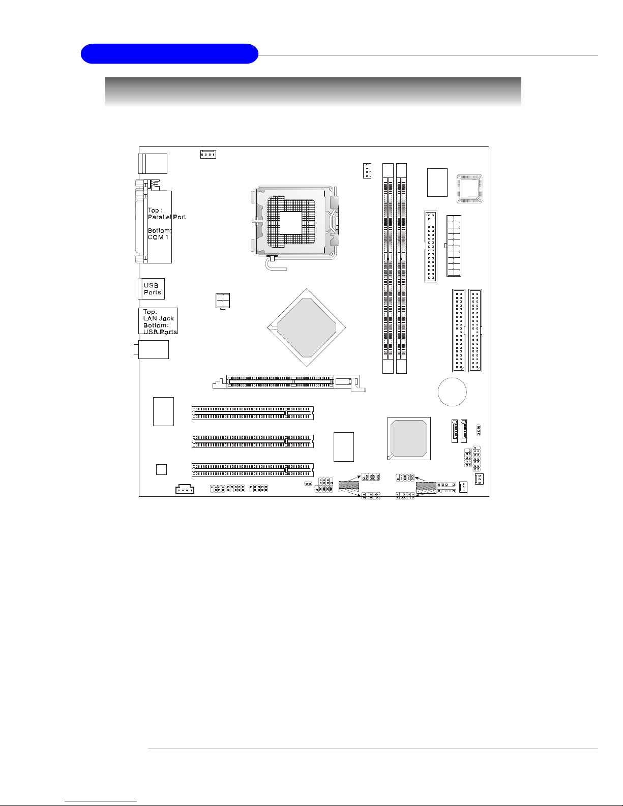
Mainboard Layout ............................................................................................... 1-4
Chapter 2. Hardware Setup .................................................................................. 2-1
Quick Components Guide ...................................................................................2-2
Central Processing Unit: CPU.............................................................................. 2-3
Example of CPU Core Speed Derivation Procedure ...................................2-3
Memory Speed/CPU FSB Support Matrix ...................................................2-3
Central Processing Unit: CPU.............................................................................. 2-4
Introduction to LGA 775 CPU ...................................................................... 2-5
CPU & Cooler Installation.............................................................................2-5
Memory ...............................................................................................................2-8
DDRModuleCombination ............................................................................ 2-8
InstallingDDR Modules ................................................................................2-8
Power Supply .....................................................................................................2-9
ATX 20-Pin Power Connector: ATX1 .......................................................... 2-9
ATX 12V Power Connector: JPW1............................................................. 2-9
BackPanel.........................................................................................................2-10
Floppy Disk Drive Connector: FDD ............................................................ 2-11
Fan Power Connectors: CPU_FAN/SYS_FAN/PWR_FAN ........................ 2-11
Connectors ....................................................................................................... 2-11
CD-In Connector: CD_IN ............................................................................2-12
Hard Disk Connectors: IDE1 & IDE2 ..........................................................2-12
IrDA Infrared Module Header: IRDA ..........................................................2-13
Front Panel Connector: JFP1, F_PANEL (Optional) ..................................2-13
Serial ATA RAID 0, 1 Connectors: SATA1, SATA2 ...................................2-14
Serial Port Header: COM2 (Optional) ........................................................2-15
Front USB Connectors: JUSB1/2 or F_USB1/2 (Optional) .......................2-15
Independent Power Switch Connector: FRISW (Optional) ......................2-16

vi
Front Panel Audio Connector: JAUD1, F_AUDIO (Optional) ....................2-16
I2C Bus Connector: I2C (Optional)............................................................2-17
IEEE 1394 Connector: J1394_1, F1_1394 (Optional) ...............................2-17
Jumper ..............................................................................................................2-18
BIOS Flash Jumper: BIOS_WP (Optional) .................................................2-18
Clear CMOS Jumper: CLR_CMOS .............................................................2-18
AGP (Accelerated Graphics Port) Slot .....................................................2-19
PCI (Peripheral Component Interconnect) Slots .......................................2-19
PCI Interrupt Request Routing ...................................................................2-19

1-1
Getting Started
Chapter 1. Getting Started
Thank you for choosing the MS-7067 v1.x Micro-ATX mainboard.
The MS-7067 mainboard is based on Intel®848P North Bridge &
ICH5 South Bridge chipsets for optimal system efficiency. Designed
to fit the advanced Intel®Pentium®4 processors in Socket LGA775,
the MS-7067 delivers a high performance and professional desktop
platform solution.
Getting Started

1-2
MS-7067 M-ATX Mainboard
Mainboard Specifications
CPU
hSupports Intel®P4 Northwood / Prescott (Socket LGA775) processor
hSupports FSB 533MHz ~ 800MHz
hSupports up to 3.6GHz and above
(For the latest information about CPU, please visit http://www.msi.com.tw/
program/products/mainboard/mbd/pro_mbd_cpu_support.php)
Chipset
hIntel® 848P chipset
- Supports 533/800MHz Intel NetBurst micro-architecture bus
- Supports AGP 8X/4X at 0.8V (AGP 3.0) or 4X at 1.5V (no support for 3.3V)
- Supports PC2100/PC2700 /PC3200 memory
hIntel®ICH5 chipset
- 8 Hi-Speed USB ports (USB2.0/1.1) controller, 480Mb/sec
- 2 Serial ATA/150 ports
- 2 channel Ultra ATA 100 bus Master IDE controller
- PCI Master v2.3
-I/O APIC
- Supports both ACPI and legacy APM power management
Main Memory
hSupports four memory banks using two 184-pin DDR DIMMs
hSupports up to 2GB DDR400/333/266 SDRAMs without ECC
(For the updated supporting memory modules, please visit http://www.msi.com.
tw/program/products/mainboard/mbd/pro_mbd_trp_list.php to refer the memory
module part in the test report.)
Slots
hOne AGP (Accelerated Graphics Port) 1.5V 8x/4x slot
hThree 32-bit PCI bus slots (support 3.3v/5v PCI bus interface)
Onboard ATA
hDual-channel Ultra DMA 33/66/100 IDE controller integrated in ICH5
- Supports PIO, Bus Master operation modes
- Can connect up to four Ultra ATA drives
hSerial ATA/150 controller integrated in ICH5
- Up to 150MB/sec transfer rate
- Can connect up to 2 Serial ATA drives
Onboard Peripherals
hOnboard Peripherals include:
- 1 floppy port supports 1 FDD with 360K, 720K, 1.2M, 1.44M and 2.88Mbytes
- 1 serial port & 1 serial header
- 1 parallel port
- 1 Line-In/Line-Out/Mic-In port

1-3
Getting Started
- 1 RJ-45 LAN Jack
- 1 CD-in (1 x 4 pin) with housing
- 8 USB2.0 ports (Rear * 4 / Front * 4)
IEEE 1394 Interface
hVIA VT6307 IEEE 1394 controller
Audio
hAC97 link controller integrated in ICH5
h6-channel software audio codec Realtek ALC655
- Compliant with AC97 v2.2 spec.
- Meets PC2001 audio performance requirement
Onboard LAN (Optional)
hRealtek 8110S / Realtek 8100 C
- Integrated Fast Ethernet MAC and PHY in one chip
- Supports 10/100Mb/s (for 8100C) and 10/100/1000Mb/s (for 8110S) auto-
negotiation operation
- Compliant with PCI v2.2, and LAN on Motherboard (LOM) standard
BIOS
hThe mainboard BIOS provides “Plug & Play” BIOS which detects the peripheral
devices and expansion cards of the board automatically
hThe mainboard provides a Desktop Management Interface (DMI) function which
records your mainboard specifications
Dimension
hMicro ATX Form Factor: 24.4cm (L) x 24.4cm (W)
Mounting
h8 mounting holes

1-4
MS-7067 M-ATX Mainboard
Mainboard Layout
MS-7067 v1.X M-ATX Mainboard
DIMM2
DIMM1
AGP1
T: mouse
B:keyboard
T: Line-Out
B:Mic
Line-In
M:
F_AUDIOJAUD1 BIOS_WP
CD_IN
Codec
VIA
VT6307
RTL8100C
BAT1
Winbond
W83627THF
Intel
ICH5
IDE1
IDE2
FDD
PCI1
PCI2
PCI3
FRISW
IRDA
PWR_FAN
CPU_FAN
SYS_FAN
F_PANEL
JPW1
ATX1
CLR_CMOS
COM2
J1394_1
F1_1394
SATA2
SATA1
BIOS
JFP1
I2C
F_USB1
JUSB1
Intel
848P
F_USB2
JUSB2

2-1
Hardware Setup
Chapter 2. Hardware Setup
Hardware Setup
This chapter provides you with the information about hard-
ware setup procedures. While doing the installation, be careful in
holding the components and follow the installation procedures. For
some components, if you install in the wrong orientation, the compo-
nents will not work properly.
Use a grounded wrist strap before handling computer
components. Static electricity may damage the components.

2-2
MS-7067 M-ATX Mainboard
Quick Components Guide
BIOS
CLR_CMOS,
p.2-18
COM2, p.2-15
DDR DIMMs, p.2-8
CPU, p.2-3
CPU_FAN, p.2-11
FDD, p.2-11
IDE1,IDE2,
p.2-12
F_USB1/2
JUSB1/2, p.2-15
JAUD1, p.2-16
JPW1, p.2-9
CD_IN, p.2-12
Back Panel
I/O, p.2-10
ATX1, p.2-9
F_AUDIO, p.2-16
SYS_FAN, p.2-11
SATA2/1,
p.2-14
JFP1
F_PANEL,
p.2-13
AGP Slot, p.2-19
PCI Slots,
p.2-19
BIOS_WP,
p.2-18 F1_1394
J1394_1,
p.2-17
PWR_FAN, p.2-11
FRISW, p.2-16
I2C, p.2-17
IRDA, p.2-13

2-3
Hardware Setup
Central Processing Unit: CPU
The mainboard supports Intel®Pentium®4 Northwood/Prescott processors in
the 775 pin package. The mainboard uses a CPU socket called LGA775 for easy CPU
installation. When you are installing the CPU, make sure the CPU has a heat sink
and a cooling fan attached on the top to prevent overheating. If you do not
have the heat sink and cooling fan, contact your dealer to purchase and install them
before turning on the computer.
For the latest information about CPU, please visit http://www.msi.com.tw/pro-
gram/products/mainboard/mbd/pro_mbd_cpu_support.php.
Example of CPU Core Speed Derivation Procedure
If CPUClock = 200MHz
Core/Bus ratio = 12
then CPU core speed = Host Clock x Core/Bus ratio
= 200MHz x 12
= 2.4 GHz
Memory Speed/CPU FSB Support Matrix
MSI Reminds You...
Overheating
Overheating will seriously damage the CPU and system, always make
sure the cooling fan can work properly to protect the CPU from
overheating.
Overclocking (Optional)
This motherboard is designed to support overclocking. However, please
make sure your components are able to tolerate such abnormal setting,
while doing overclocking. Any attempt to operate beyond product speci-
fications is not recommended. We do not guarantee the damages
or risks caused by inadequate operation or beyond product
specifications.
FSB
Memory DDR266 DDR333
533 MHz
800 MHz
OK
OK
DDR400
OK
OK
OK
N/A

2-4
MS-7067 M-ATX Mainboard
Central Processing Unit: CPU
The mainboard supports Intel®Pentium 4 Prescott processor. The mainboard
uses a CPU socket called LGA775. When you are installing the CPU, make sure to
install the cooler to prevent overheating. If you do not have the CPU cooler,
contact your dealer to purchase and install them before turning on the computer.
For the latest information about CPU, please visit http://www.msi.com.tw/
program/products/mainboard/mbd/pro_mbd_cpu_support.php.
MSI Reminds You...
Overheating
Overheating will seriously damage the CPU and system, always make
sure the cooling fan can work properly to protect the CPU from
overheating.
Replacing the CPU
While replacing the CPU, always turn off the ATX power supply or
unplug the power supply’s power cord from grounded outlet first to
ensure the safety of CPU.
Overclocking (Optional)
This motherboard is designed to support overclocking. However, please
make sure your components are able to tolerate such abnormal setting,
while doing overclocking. Any attempt to operate beyond product speci-
fications is not recommended. We do not guarantee the damages
or risks caused by inadequate operation or beyond product
specifications.
Introduction to LGA 775 CPU The surface of LGA 775 CPU.
Remember to apply some sili-
cone heat transfer compound on
it for better heat dispersion.
Golden triangle is the Pin 1 indicator
The pin-pad side of LGA 775
CPU.
Golden triangle is the Pin 1 indicator
Alignment Key Alignment Key

2-5
Hardware Setup
2. Remove the cap from lever hinge
side (as indicated by the arrow).
1. The CPU has a plastic cap on it to
protect the contact from damage.
Before you install the CPU, always
cover it to protect the socket pin.
3. The pins of socket reveal.
CPU & Cooler Installation
When you are installing the CPU, make sure the CPU has a cooler at-
tached on the top to prevent overheating. If you do not have the cooler, contact
your dealer to purchase and install them before turning on the computer. Meanwhile,
do not forget to apply some silicon heat transfer compound on CPU before installing
the heat sink/cooler fan for better heat dispersion.
Follow the steps below to install the CPU & cooler correctly. Wrong installation
will cause the damage of your CPU & mainboard.
4. Open the load lever.

2-6
MS-7067 M-ATX Mainboard
6. After confirming the CPU direction
for correct mating, put down the
CPU in the socket housing frame.
Be sure to grasp on the edge of
the CPU base. Note that the align-
ment keys are matched.
8. Cover the load plate onto the
package.
7. Visually inspect if the CPU is
seated well into the socket. If not,
take out the CPU with pure vertical
motion and reinstall.
alignment
key
5. Lift the load lever up and open the
load plate.

2-7
Hardware Setup
10. Align the holes on the mainboard
with the heatsink. Push down the
cooler until its four clips get
wedged into the holes of the
mainboard.
12.Turn over the mainboard to con-
firm that the clip-ends are cor-
rectly inserted.
11. Press the four hooks down to fas-
ten the cooler. Then rotate the lock-
ing switch (refer to the correct di-
rection marked on it) to lock the
hooks.
9. Press down the load lever lightly
onto the load plate, and then se-
cure the lever with the hook under
retention tab.
locking
switch
MSI Reminds You...
1.Confirm if your CPU cooler is firmly installed before turning on your
system.
2.Check the information in PC Health Status of H/W Monitor in BIOS
for the CPU temperature.
3.Do not touch the CPU socket pins to avoid damage.
4. Whenever CPU is not installed, always protect your CPU socket pins
with the plastic cap covered (shown in Figure 1) to avoid damage.
5. Please note that the mating/unmating durability of the CPU is 20 cycles.
Therefore we suggest that you do not plug/unplug the CPU too often.

2-8
MS-7067 M-ATX Mainboard
Installing DDR Modules
1. The DDR DIMM has only one notch on the center of module. The module will only fit
in the right orientation.
2. Insert the DIMM memory module vertically into the DIMM slot. Then push it in until the
golden finger on the memory module is deeply inserted in the socket.
3. The plastic clip at each side of the DIMM slot will automatically close.
Volt Notch
DDR Module Combination
Install at least one DIMM module on the slot. Memory modules can be installed
on the slots in any order. You can install either single- or double-sided modules to
meet your own needs.
Memory modules can be installed in any combination as follows:
S: Single Side D: Double Side
The mainboard provides 2 slots for 184-pin DDR SDRAM DIMM (Double In-Line
Memory Module) modules and supports the memory size up to 2GB. You can install
DDR400/333/266 modules on the DDR DIMM slots (DIMM 1~2).
For the updated supporting memory modules, please visit http://www.msi.com.
tw/program/products/mainboard/mbd/pro_mbd_trp_list.php.
Memory
MSI Reminds You...
You can barely see the golden finger if the module is properly inserted
in the socket.
Slot Memory Module Total Memory
DIMM1 S/D 64MB~1GB
DIMM2 S/D 64MB~1GB
Maximum System Memory Supported 64MB~2GB

2-9
Hardware Setup
Power Supply
The mainboard supports ATX power supply for the power system. Before
inserting the power supply connector, always make sure that all components are
installed properly to ensure that no damage will be caused.
ATX 20-Pin Power Connector: ATX1
This connector allows you to connect to an ATX power supply. To connect to
the ATX power supply, make sure the plug of the power supply is inserted in the
proper orientation and the pins are aligned. Then push down the power supply firmly
into the connector.
ATX 12V Power Connector: JPW1
This 12V power connector is used to provide power to the CPU.
PIN SIGNAL
11 3.3V
12 -12V
13 GND
14 PS_ON
15 GND
16 GND
17 GND
18 -5V
19 5V
20 5V
PIN SIGNAL
1 3.3V
2 3.3V
3 GND
45V
5 GND
65V
7 GND
8 PW_OK
9 5V_SB
10 12V
ATX1 Pin Definition
PIN SIGNAL
1 GND
2 GND
312V
412V
JPW1 Pin Definition
ATX1
10
1
20
11
JPW1
1
3
4
2

2-10
MS-7067 M-ATX Mainboard
Back Panel
Mouse/Keyboard Connector
Pin1
Mouse/KBD
DATA
Pin2 NC
Pin3 GNDPin4VCC
Pin5
Mouse/KBD Clock
Pin6 NC
USB Ports
1 2 3 4 PIN SIGNAL
1 VCC
2 -Data
3 +Data
4 GND
PIN SIGNAL DESCRIPTION
1 TDP Transmit Differential Pair
2 TDN Transmit Differential Pair
3 RDP ReceiveDifferentialPair
4 NC NotUsed
5 NC NotUsed
6 RDN ReceiveDifferentialPair
7 NC NotUsed
8 NC NotUsed
Mouse Parallel
Keyboard COM1 USB Ports
L-In
MIC
L-Out
LAN
PIN SIGNAL
1 DCD
2 SIN
3 SOUT
4 DTR
5 GND
6 DSR
7 RTS
8 CTS
9RI
1 2 3 4 5
6 7 8 9
RJ-45 LAN Jack
Serial Port
10/100 LAN (for 8100C)
Gigabit LAN (for 8110S)
81
PIN SIGNAL DESCRIPTION
1 D0P Differential Pair 0+
2 D0N Differential Pair 0-
3 D1P Differential Pair 1+
4 D2P Differential Pair 2+
5 D2N Differential Pair 2-
6 D1N Differential Pair 1-
7 D3P Differential Pair 3+
8 D3N Differential Pair 3-
Table of contents
Other MSI Motherboard manuals

MSI
MSI MEG Z590 UNIFY-X User manual

MSI
MSI Z790-S01 User manual

MSI
MSI G31M2 Series User manual

MSI
MSI MAG B660 TOMAHAWK WIFI DDR4 User manual

MSI
MSI 945G Neo2 Series User manual

MSI
MSI KT4A-V User manual

MSI
MSI MS-6380E User manual

MSI
MSI MEG Z690 UNIFY-X User manual

MSI
MSI MS-7043 User manual

MSI
MSI A520M PRO User manual

MSI
MSI MS-7071 User manual

MSI
MSI P45-8D Series User manual

MSI
MSI B450M BAZOOKA V2 User manual

MSI
MSI IA-Q45 User manual

MSI
MSI 655 Max User manual

MSI
MSI P7N SLI PLATINUM - Motherboard - ATX User manual

MSI
MSI 890FXA-GD70 series User manual

MSI
MSI P55-CD53 series User manual

MSI
MSI MPG Z390I GAMING EDGE AC User manual

MSI
MSI X299 XPOWER GAMING AC User manual