MSI Z790-S01 User manual

Z790-S01
Motherboard
User Guide
Benutzerhandbuch
Manuel d’utilisation
Руководство пользователя
取扱説明書
사용 명서
使用手冊
使用手册

1
Contents
Quick Start..................................................................................................................... 3
Specifications.............................................................................................................. 15
Special Features......................................................................................................... 18
Package Contents ...................................................................................................... 19
Back Panel Connectors ............................................................................................. 20
LAN Port LED Status Table .................................................................................. 21
Audio Jacks Connection ....................................................................................... 21
Overview of Components........................................................................................... 23
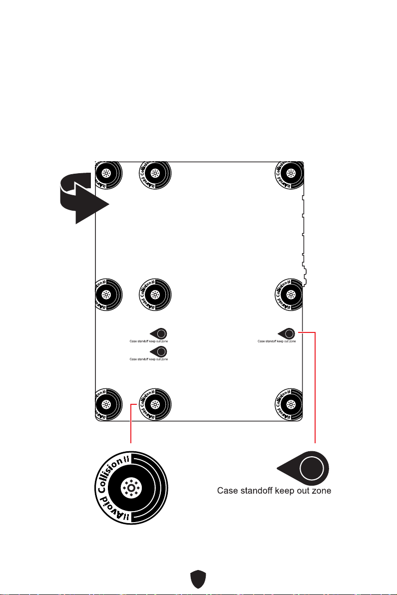
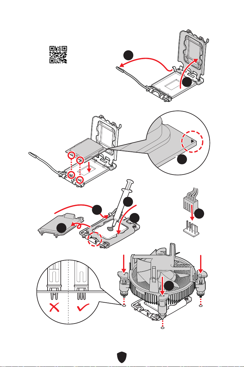
CPU Socket ........................................................................................................... 24
DIMM Slots............................................................................................................ 25
PCI_E1~5: PCIe Expansion Slots.......................................................................... 26
M2_WIFI1: M.2 Slot (Key E) .................................................................................. 26
M2_1~2: M.2 Slots (Key M) ................................................................................... 27
SATA5~8: SATA 6Gb/s Connectors....................................................................... 29
JTBT1: Thunderbolt Add-on Card Connector ...................................................... 29
JAUD1: Front Audio Connector ............................................................................ 30
JFP1, JFP2: Front Panel Connectors................................................................... 30
CPU_PWR1~2, ATX_PWR1: Power Connectors................................................... 31
JCI1: Chassis Intrusion Connector....................................................................... 32
JUSB3~4: USB 3.2 Gen 1 Connectors .................................................................. 33
JUSB1~2: USB 2.0 Connectors............................................................................. 34
JTPM1: TPM Module Connector........................................................................... 34
CPU_FAN1, PUMP_FAN1, SYS_FAN1~4: Fan Connectors.................................. 35
JBAT1: Clear CMOS (Reset BIOS) Jumper........................................................... 36
BAT1: CMOS Battery............................................................................................ 37
JRGB1: RGB LED connector................................................................................. 38
Installing OS, Drivers & MSI Center.......................................................................... 39
MSI Center............................................................................................................ 42
English

2
UEFI BIOS.................................................................................................................... 43
BIOS Setup............................................................................................................ 44
Resetting BIOS...................................................................................................... 45
Updating BIOS....................................................................................................... 45

3
Quick Start
Thank you for purchasing a new motherboard from MSI®. This Quick Start section
provides demonstration diagrams about how to install your computer. Some of the
installations also provide video demonstrations. Please link to the URL to watch it
with the web browser on your phone or tablet. You may have even link to the URL by
scanning the QR code.
Preparing Tools and Components
Intel® LGA1700 CPU
LGA1700 CPU Fan
Graphics Card
SATA Hard Disk Drive
Phillips Screwdriver
Chassis
Power Supply Unit
A Package of Screws
Thermal Paste
DDR5 Memory

4
Safety Information
∙The components included in this package are prone to damage from electrostatic
discharge (ESD). Please adhere to the following instructions to ensure successful
computer assembly.
∙Ensure that all components are securely connected. Loose connections may cause
the computer to not recognize a component or fail to start.
∙Hold the motherboard by the edges to avoid touching sensitive components.
∙It is recommended to wear an electrostatic discharge (ESD) wrist strap when
handling the motherboard to prevent electrostatic damage. If an ESD wrist strap
is not available, discharge yourself of static electricity by touching another metal
object before handling the motherboard.
∙Store the motherboard in an electrostatic shielding container or on an anti-static
pad whenever the motherboard is not installed.
∙Before turning on the computer, ensure that there are no loose screws or metal
components on the motherboard or anywhere within the computer case.
∙Do not boot the computer before installation is completed. This could cause
permanent damage to the components as well as injury to the user.
∙If you need help during any installation step, please consult a certified computer
technician.
∙Always turn off the power supply and unplug the power cord from the power outlet
before installing or removing any computer component.
∙Keep this user guide for future reference.
∙Keep this motherboard away from humidity.
∙Make sure that your electrical outlet provides the same voltage as is indicated on
the PSU, before connecting the PSU to the electrical outlet.
∙Place the power cord such a way that people can not step on it. Do not place
anything over the power cord.
∙All cautions and warnings on the motherboard should be noted.
∙If any of the following situations arises, get the motherboard checked by service
personnel:
• Liquid has penetrated into the computer.
• The motherboard has been exposed to moisture.
• The motherboard does not work well or you can not get it work according to user
guide.
• The motherboard has been dropped and damaged.
• The motherboard has obvious sign of breakage.
∙Do not leave this motherboard in an environment above 60°C (140°F), it may damage
the motherboard.

5
Case stand-off notification
To prevent damage to the motherboard, any unnecessary mounting stand-off between
the motherboard circuits and the computer case is prohibited. The Case standoff keep
out zone signs will be marked on the backside of motherboard (as shown below) to
serve as a warning to user.
Avoid collision notification
Protective paint is printed around each screw hole to prevent parts from being
scratched.

6
Installing a Processor
⚽
∙https://youtu.be/KMf9oIDsGes
11
22
33
66
44
5577
88
99

7
Installing DDR5 memory
DIMMA2 DIMMA2
DIMMB2
DIMMA1
DIMMA2
DIMMB1
DIMMB2
∙https://youtu.be/XiNmkDNZcZk
⚽

8
HDD LED
RESET SW
Connecting the Front Panel Header
∙http://youtu.be/DPELIdVNZUI
JFP1
HDD LED HDD LED -
HDD LED +
POWER LED -
POWER LED +
POWER LED
RESET SW
POWER SW
POWER LED+
POWER LED-
HDD LED
⚽
1
2 10
9
Power LED
Reserved
Power Switch
JFP1
Reset SwitchHDD LED

9
BAT1
Installing the Motherboard
11
∙https://youtu.be/wWI6Qt51Wnc
⚽
Torque:
3 kgf·cm*
*3 kgf·cm
= 0.3 N·m
= 2.6 lbf·in
22

10
Connecting the Power Connectors
∙http://youtu.be/gkDYyR_83I4
CPU_PWR1
⚽
CPU_PWR2
ATX_PWR1

11
Installing SATA Drives
∙http://youtu.be/RZsMpqxythc
11
2233
44
55
⚽

12
Installing a Graphics Card
∙http://youtu.be/mG0GZpr9w_A
⚽
11
22
33
44
55
66

13
Connecting Peripheral Devices

14
Power On
44
33
1122

15
Specifications
CPU
∙Supports 12th/ 13th Gen Intel® Core™ Processors,
Pentium® Gold and Celeron® Processors*
∙Processor socket LGA1700
* Please go to www.msi.com to get the newest support status as new processors
are released.
Chipset Intel® Z790 Chipset
Memory
∙4x DDR5 memory slots, supporting up to 192GB*
∙Supports 1R 5600 MHz (by JEDEC & POR)
∙Max. overclocking frequency:
• 1DPC 1R Max speed up to 6600+ MHz
• 1DPC 2R Max speed up to 6400+ MHz
• 2DPC 1R Max speed up to 6000+ MHz
• 2DPC 2R Max speed up to 5600+ MHz
∙Supports Intel® XMP 3.0 OC
∙Supports Dual-Controller Dual-Channel mode
∙Supports non-ECC, un-buffered memory
* Please refer to www.msi.com for more information on compatible memory.
Expansion Slots
∙2x PCIe x16 slots
• PCI_E1 slot (From CPU)
• Supports up to PCIe 5.0 x16
• PCI_E3 slot (From Z790 chipset)
• Supports up to PCIe 3.0 x4
∙3x PCIe x1 slots
• PCI_E2 , PCI_E4 and PCI_E5 slots (From Z790 chipset)
• Supports up to PCIe 3.0 x1
∙1x M.2 slot (M2_WIFI1) with E-key for PCIe WiFi module
only
Onboard Graphics
∙1x HDMI™ 1.4 port with HDR, supports a maximum
resolution of 4K 30Hz*/ **
∙1x DisplayPort 1.4, supports a maximum resolution of 4K
60Hz */ **
* Available only on processors featuring integrated graphics.
** Graphics specifications may vary depending on the CPU installed.
SATA Ports ∙4x SATA 6Gb/s ports (From Z790 chipset)
Continued on next column

16
Continued from previous column
M.2 SSD Slots
∙2x M.2 slots (Key M)
• M2_1 slot (From CPU)
• Supports up to PCIe 4.0 x4
• Supports 2242/ 2260/ 2280/ 22110 storage devices
• M2_2 slot (From Z790 chipset)
• Supports up to PCIe 4.0 x4
• Supports SATA 6Gb/s
• Supports 2242/ 2260/ 2280 storage devices
RAID ∙Supports RAID 0, RAID 1, RAID 5 and RAID 10 for SATA
storage devices
Audio
Realtek® ALC897 Codec
∙7.1-Channel High Definition Audio
∙Supports S/PDIF output
LAN ∙1x Realtek® RTL8125BG 2.5Gbps LAN controller
Power Connectors ∙1x 24-pin ATX main power connector
∙2x 8-pin +12V power connectors
Internal USB
Connectors
∙2x USB 3.2 Gen 1 5Gbps connectors (From Z790 chipset)
• Supports additional 4 USB 3.2 Gen 1 5Gbps ports
∙2x USB 2.0 connectors (From Z790 chipset)
• Supports additional 4 USB 2.0 ports
Fan Connectors
∙1x 4-pin CPU fan connector
∙1x 4-pin water-pump fan connector
∙4x 4-pin system fan connectors
System Connectors
∙1x Front panel audio connector
∙2x System panel connectors
∙1x Chassis Intrusion connector
∙1x TPM module connector
∙1x TBT connector (Supports RTD3)
Jumpers ∙1x Clear CMOS jumper
LED Features ∙1x 4-pin RGB LED connector
Continued on next column

17
Continued from previous column
Back Panel
Connectors
∙1x DisplayPort
∙1x HDMI™ port
∙2x USB 2.0 Type-A ports (From Z790 chipset)
∙4x USB 3.2 Gen 1 5Gbps Type-A ports (From Z790 chipset)
∙1x USB 3.2 Gen 2x2 20Gbps Type-C port (From Z790
chipset)
∙1x 2.5Gbps LAN (RJ45) port
∙5x Audio jacks
∙1x Optical S/PDIF out connector
I/O Controller NUVOTON NCT6687 Controller Chip
Hardware Monitor
∙CPU/ System/ Chipset temperature detection
∙CPU/ System/ Pump fan speed detection
∙CPU/ System/ Pump fan speed control
Form Factor ∙ATX Form Factor
∙9.6 in. x 12 in. (244 mm x 305 mm)
BIOS Features
∙1x 256 Mb flash
∙UEFI AMI BIOS
∙ACPI 6.4, SMBIOS 3.5
∙Multi-language
Software
∙Drivers
∙MSI Center
∙Intel Extreme Tuning Utility
∙CPU-Z MSI GAMING
∙Norton 360 Deluxe
∙AIDA64 Extreme - MSI Edition

18
Special Features
MSI Center
• Mystic Light
• Ambient Link
• Frozr AI Cooling
• User Scenario
• True Color
• Live Update
• Hardware Monitoring
• Super Charger
• Devices Speed Up
• Smart Image Finder
• MSI Companion
• System Diagnosis
Thermal Features
• Fan headers (CPU + PUMP +
SYSTEM)
• Extended Heatsink Design
• M.2 Shield Frozr
• 7W/mk MOSFET thermal pad
Performance
• Core Boost
• VRM Power Design (VCPU / VGT /
AUX)
• Dual CPU Power
• Memory Boost
• Lightning Gen 5 PCI-E Slot
• Lightning Gen 4 M.2 Slot
• Server Grade PCB
• Game Boost
• Lightning USB 20G
• USB with Type A+C
DIY Friendly
• PCI-E Steel Armor
Audio
• Audio Boost
RGB Support
• Mystic Light
• Mystic Light Extension (RGB)
• Ambient Link Support
BIOS
• Click BIOS 5

19
Package Contents
Please check the contents of your motherboard package. It should contain:
Board
• 1x Motherboard
Documentation
• 1x Quick installation guide
• 1x European Union regulatory notice
Cables
• 2x SATA 6Gb/s cables
Accessories
• 1x I/O shielding
• 1x HDMI dust cover
• 1x DP dust cover
⚠
Important
If any of the above items are damaged or missing, please contact your retailer.
Other manuals for Z790-S01
1
Table of contents
Other MSI Motherboard manuals

MSI
MSI MPG X570 GAMING PRO CARBONWIFI User manual

MSI
MSI Z68A-GD65 B3 series User manual

MSI
MSI MS-7596 (v1.x) User manual

MSI
MSI KM4M Series User manual

MSI
MSI MPG B550I GAMING EDGE WIFI User manual

MSI
MSI H170A GAMING PRO User manual

MSI
MSI 990FXA-GD80 series User manual

MSI
MSI MEG B550 UNIFY-X User manual

MSI
MSI 975X Platinum Series User manual

MSI
MSI MS-98H6 User manual

MSI
MSI B75A-G43 series User manual

MSI
MSI 890GXM User manual

MSI
MSI G965MDH Series User manual

MSI
MSI K9AG Neo2-Digital User manual

MSI
MSI MS-7222 User manual

MSI
MSI H6M-E33 (G3) User manual

MSI
MSI B450 TOMAHAWK MAX User manual

MSI
MSI 7C04-001R User manual

MSI
MSI H310M PRO-VH User manual

MSI
MSI MEG Series User manual