4
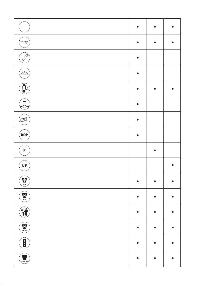
1. CARACTERÍSTICAS PRINCIPALES
UV LED
ROP F UF
Con lámpara UV LED bactericida
CAPSULATED MEMBRANE
Membrana Instalada. Máxima higiene
COLUMBIA FILTERS
Filtros originales Columbia de conexión rápida.
REMINERALIZER
Postfiltro ajustador de pH
CLICK
Conexiones rápidas y de máxima seguridad
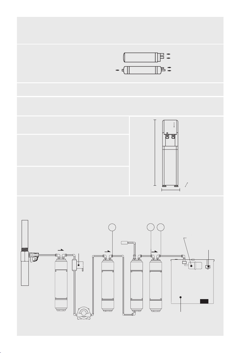
PRESSURE PUMP
Mayor producción y rendimiento
SOLENOID VALVE
Control inmediato.
REVERSE OSMOSIS
Equipo con sistema de ósmosis
inversa y bomba
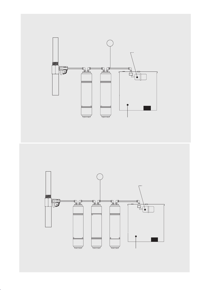
FILTER
Equipo con sistema de filtración
ULTRAFILTRATION
Equipo con sistema de ultra-filtración
COLD
Producción de agua fría
HOT
Producción de agua caliente
SAVE
Sistema de seguridad para agua caliente
AMBIENT
Producción de agua a temperatura ambiente.
Desconectando la caliente
LED
Sistema de información multifunción mediante LED
ANTIBACTERIA
Protector para la salida de los grifos fabricado en plástico antibacteriano.
Extraíble y lavable.
ENERGY SAVE
Sistema de ahorro de energía. Un sensor de luminosidad deja parte de la fuente
en stand by durante la noche para reducir el consumo eléctrico.
UV Ease of access and maintenance
Fast connection, original Columbia filters
Membrane Installed. Maximum hygiene
Post-filter that adjusts the pH
Rapid and highly secure connections
Better production and performance
Immediate Control.
Equipment with reverse osmosis
system and pump
Equipment with filtration system
Equipment with ultrafiltration system
Cold water production
Hot water production
Safety system for hot water
Production of room temperature water
Heat disabler
LED multifunction information system
Protector for faucet outlets made of antibacterial plastic. Removable and
washable