-7- -8-
3CAMERA
CONTRAST
- Display PICTURE set-up Screen by pressing the MENU Key twice
and locate the cursor at CONTRAST by SCAN and/or CA,SEL Keys.
- Adjust the Contrast by the Volume Up/Down Keys.
0 ~ 100 / 50 : Factory Default
BRIGHTNESS
- After locating the cursor at BRIGHT by SCANand/or CA.SEL Keys,
adjust the Brightness by the Volume Up/Down Keys.
0 ~ 100 / 50 : Factory Default
COLOR
- After locating the cursor at COLOR by SCAN and/or CA.SEL Keys,
adjust the Color by the Volume Up/Down Keys.
0 ~ 100 / 50 : Factory Default
TINT
- After locating the cursor at TINT by SCAN and/or CA.SEL Keys,
adjust the Tint by the Volume Up/Down Keys.
0 ~100 / 50 : Factory Default
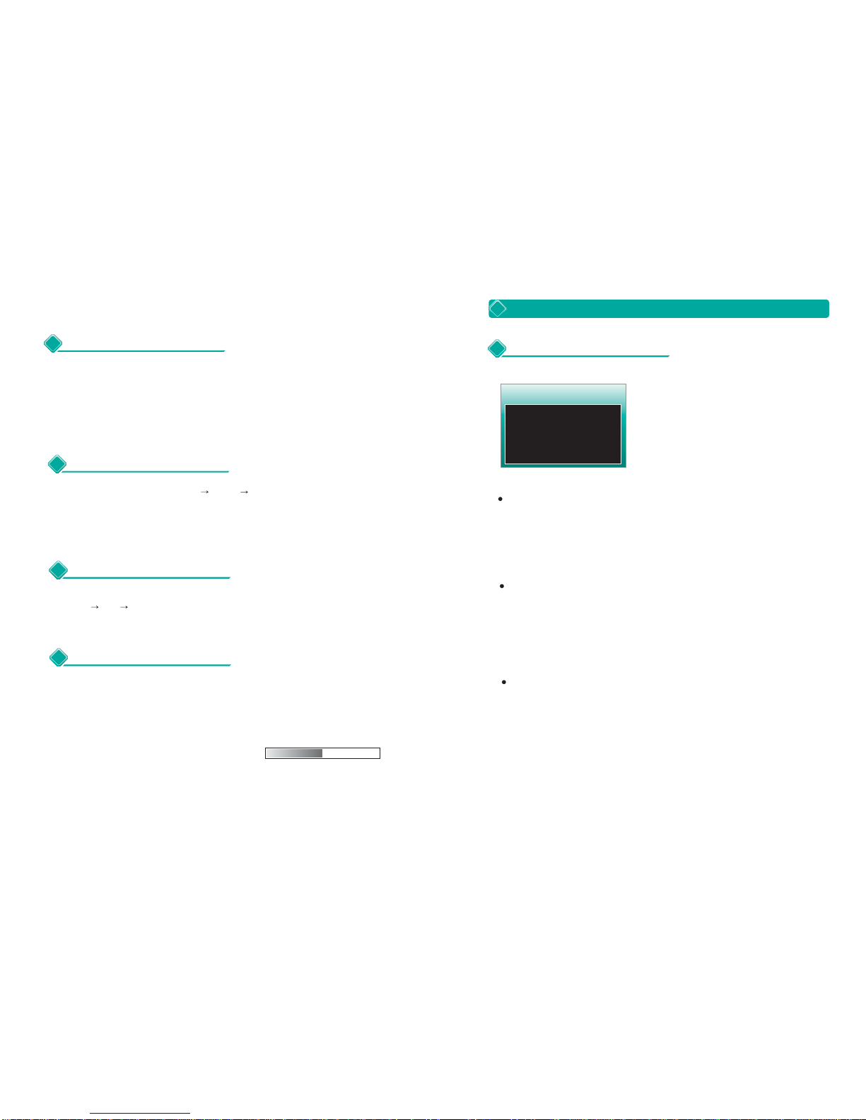
2PICTURE
PICTURE
CONTRAST
BRIGHT
COLOR
TINT
50 (0-100)
50 (0-100)
50 (0-100)
50 (0-100)
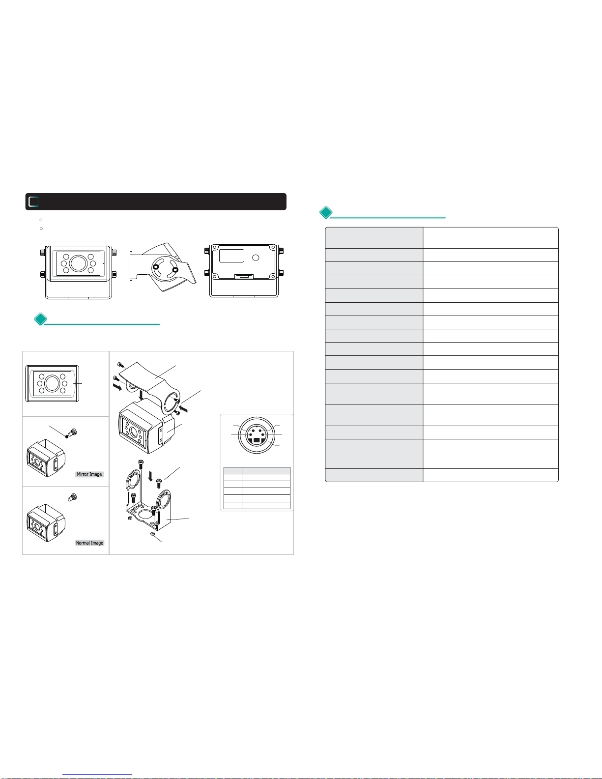
NOR/MIR
NOR/MIR
NOR/MIR
CAMERA
CA1 SCAN
CA2 SCAN
CA3 SCAN
CA1 TRIG
0 ~ 9
0 ~ 9
0 ~ 9
0 ~ 9
CA3 TRIG 0 ~ 9
CA2 TRIG 0 ~ 9
CA1 TRIG
CA1 SCAN
- After locating the cursor at CA 1 SCAN by SCANand/or CA.SEL Keys,
select the desired delaying time for the selected viewing mode among
0 ~ 9 seconds by Volume Up/Down Keys.
- Factory Default : 3 second
CA2 SCAN
- After locating the cursor at CA 2 SCAN by SCANand/or CA.SEL Keys,
select the desired delaying time for the selected viewing mode among
0 ~ 9 seconds by Volume Up/Down Keys.
- Factory Default : 3 seconds
CA3 SCAN
- After locating the cursor at CA 3 SCAN by SCANand/or CA.SEL Keys,
select the desired delaying time for the selected viewing mode among
0 ~ 9 seconds by Volume Up/Down Keys.
- Factory Default : 3 seconds
- After locating the cursor at CA 1 TRIG by SCANand/or CA.SEL Keys,
select the desired delaying time for the selected viewing mode among
0 ~ 9 seconds by Volume Up/Down Keys.
- Factory Default : 3 seconds
- After locating the cursor at CA 2 TRIG by SCANand/or CA.SEL Keys,
select the desired delaying time for the selected viewing mode among
0 ~ 9 seconds by Volume Up/Down Keys.
- Factory Default : 3 seconds
CA3 TRIG
- After locating the cursor at CA 3 TRIG by SCANand/or CA.SEL Keys,
select the desired delaying time for the selected viewing mode among
0 ~ 9 seconds by Volume Up/Down Keys.
- Factory Default : 3 seconds
CA2 TRIG