6Section 3— ASSembly & Set-Up
Assembly - Husqvarna
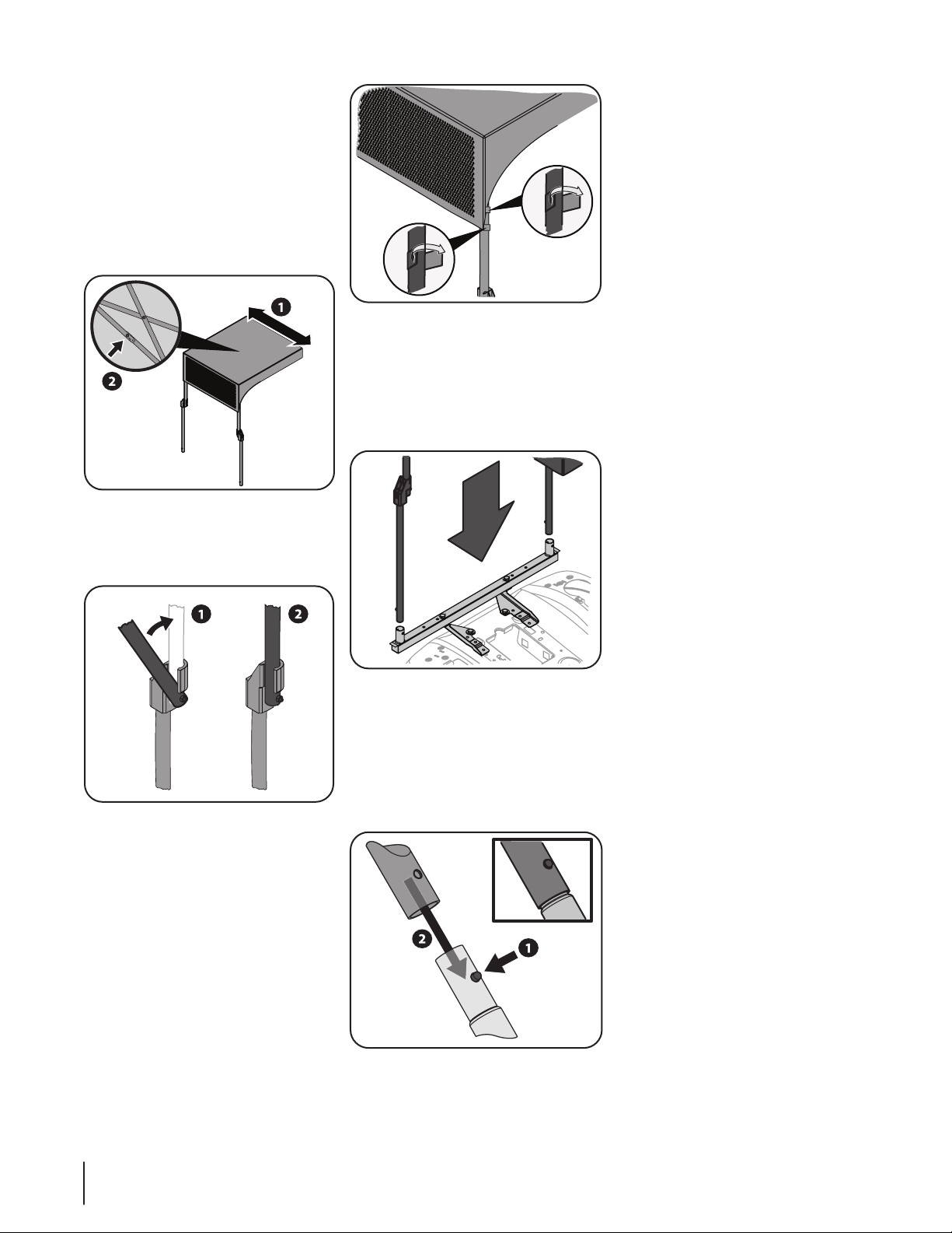
1. Flip tractor seat up.
2. Remove seat springs and mounting
hardware. Set aside for re-use.
3. Assemble Support (683-05347) and
Mounting Brackets (789-00433,
789-00434) by using 2 Hex Head
Capscrews (710-3180) and 2 nuts
(712-04063) as shown in Figure 3-4.
Figure 3-4
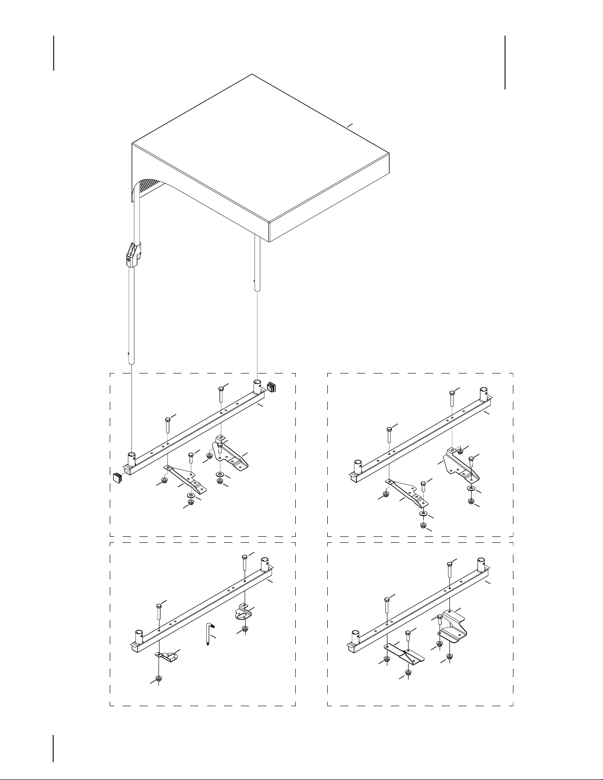
4. Use two Hex Head Capscrews (710-
0376), two Washers (736-0159), and
two Nuts (712-04063) to install the
Support assembly on rear of tractor
as shown in Figure 3-5.
Figure 3-5
NOTE: All references to LEFT, RIGHT,
FRONT, and REAR indicate the sun shade
position when sitting in the tractor seat in
the operator’s position.
CAUTION: Do not transport
the tractor on a trailer or in the
bed of a truck with the sun
shade installed.
CAUTION: Do not operate
tractor with universal sun
shade installed in headwinds
of excess of 15 mph.
Assembly
Before beginning installation, remove
all parts from the carton to make sure
everything is present. Carton contents are
listed on page 5.
This kit contains multiple mounting
brackets for various makes and models of
tractors. Identify the appropriate kit for
your tractor:
• Cub Cadet XT Enduro Series, Troy-Bilt
Super Bronco / Husqvarna – 789-
00433, 789-00434
• Troy-Bilt Bronco, Troy-Bilt Pony, Troy-
Bilt Horse – 789-00425, 789-00424
• John Deere – 789-00399, 789-00400
Note: Each Mounting Bracket kit has a
Right and Left Hand specific mounting
bracket.
Required Tools List
• 1/2” Socket
• 1/2” Wrench
• Ratchet
• Socket Extension (if needed)
• Torx T30 (Included with Hardware
Pack)
Assembly – Cub Cadet XT Enduro
Series, Troy-Bilt Super Bronco
1. Flip tractor seat up.
2. Remove seat springs and mounting
hardware. Set aside.
3. Assemble Support (683-05347) and
Mounting Brackets (789-00433,
789-00434) by using 2 Hex Head
Capscrews (710-3180) and 2 nuts
(712-04063) as shown in Figure 3-1.
Figure 3-1
4. Use two Hex Head Capscrews (710-
0376), two Washers (736-0159), and
two Nuts (712-04063) to install the
Support assembly on rear of tractor
as shown in Figure 3-2.
Figure 3-2
5. Reinstall the seat springs and
hardware that were removed earlier
in the procedure as shown in Figure
3-3.
Figure 3-3