MTD 530 Series User manual

IMPORTANT: READ SAFETY RULES AND INSTRUCTIONS CAREFULLY
MTD PRODUCTS INC. P.O. BOX 368022 CLEVELAND, OHIO 44136-9722
Model Series
530
PRINTED IN U.S.A. FORM NO.770-1057A
Warning: This unit is equipped with an internal combustion engine and should not be used on or near any unimproved forest-
covered, brush-covered or grass-covered land unless the engine’s exhaust system is equipped with a spark arrester meeting
applicable local or state laws (if any). If a spark arrester is used, it should be maintained in effective working order by the operator.
In the State of California the above is required by law (Section 4442 of the California Public Resources Code). Other states may have
similar laws. Federal laws apply on federal lands. A spark arrester for the muffler is available through your nearest engine authorized
service dealer or contact the service department, P.O. Box 368022 Cleveland, Ohio 44136-9722.
OPERATOR’S MANUAL
12/97

SECTION 1: IMPORTANT SAFE OPERATION PRACTICES
WARNING: THIS SYMBOL POINTS OUT IMPORTANT SAFETY INSTRUCTIONS WHICH, IF
NOT FOLLOWED, COULD ENDANGER THE PERSONAL SAFETY AND/OR PROPERTY OF
YOURSELF AND OTHERS. READ AND FOLLOW ALL INSTRUCTIONS IN THIS MANUAL
BEFORE ATTEMPTING TO OPERATE YOUR EDGER. FAILURE TO COMPLY WITH THESE
INSTRUCTIONS MAY RESULT IN PERSONAL INJURY. WHEN YOU SEE THIS SYMBOL HEED
ITS WARNING.
WARNING: The Engine Exhaust from this product contains chemicals known to
the State of California to cause cancer, birth defects or other reproductive harm.
DANGER: Your edger was built to be operated according to the rules for safe operation in this
manual. As with any type of power equipment, carelessness or error on the part of the operator can
result in serious injury. If you violate any of these rules, you may cause serious injury to yourself or
others.
1. TRAINING AND PREPARATION
•Read the operator’s manual carefully. Be
thoroughly familiar with the controls and proper
use of the equipment. Know how to disengage the
blade control and stop the unit quickly.
•Never allow children to operate equipment. Never
allow adults to operate equipment without proper
instruction.
•Keep the area of operation clear (at least 50 feet)
of all persons, especially small children and pets.
•Use the edger only as manufacture intended and
as described in the operator’s manual.
•Do not operate edger after it has been dropped or
damaged.
•Return product to nearest authorized service
facility for examination and repair. Do not operate
product with damaged or excessively worn cutting
blade.
•Dress properly-always wear safety glasses or
goggles. Always wear safety footwear, and pants
or slacks that cover your legs to reduce the risk of
injury that may be caused by flying debris. Do not
wear loose clothing or jewelry that can be caught
in moving parts. Use of gloves and substantial
footwear is recommended when working outdoors.
Do not operate edger when barefoot or wearing
sandals or open-toed shoes. Wear boots,
preferably with steel-toe caps.
•Objects struck by the blade can cause severe
injuries to persons. The work area should always
be carefully examined and cleared of all stones,
sticks, wires, bones and other foreign
•objects, prior to edging.
•Never attempt to make any adjustments, other
than depth of cut, while engine is running.
•The use of accessory attachments not
recommended by the manufacturer may cause
hazard and will void warranty.
•Never operate the edger without proper guards,
plates or other safety protective devices in place.
•Turn engine off and disconnect spark plug wire:
•When not in use.
•Before servicing, cleaning and the like.
•Before changing accessories.
•Handle fuel with care; it is highly flammable
•Extinguish all smoking materials and other
possible sources of ignition.
•Use a fuel container acceptable for the purpose.
•Never add fuel to a running or hot engine.
•Fill fuel tank outdoors with extreme care. Never fill
fuel tank indoors.
•Replace gasoline cap securely.
•If fuel is spilled, move product and fuel container
from area and do not create a source of ignition.
Wipe up spilled fuel.
2. OPERATION
•Make sure all nuts, bolts, and screws are kept
tightly in place, especially the blade and all guards.
•Start the engine carefully. Make certain the blade
is disengaged before attempting to start. Keep
hands, feet, clothing, and the like well away from
cutting blade and moving parts.
DANGER: ROTATING CUTTING BLADE
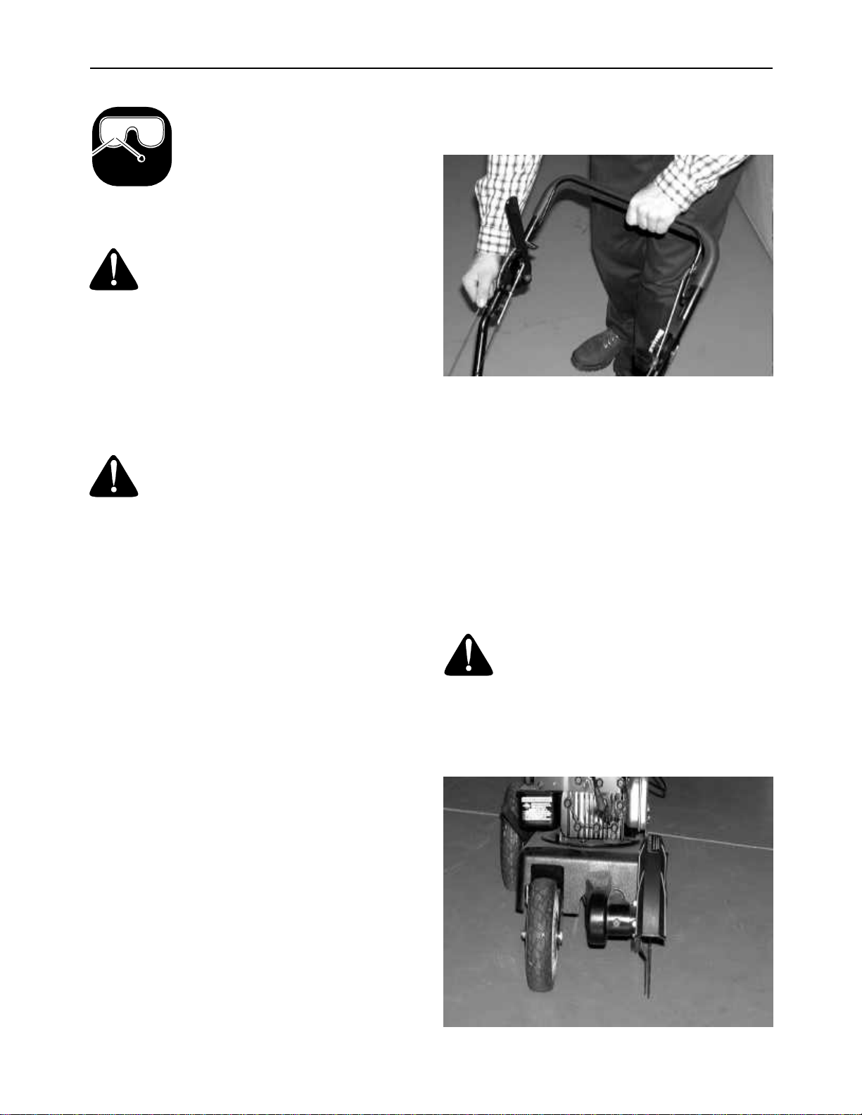
•Keep both hands on handles when blade is
rotating.
•Keep feet away from cutting area.

3
•Make sure engine is off and spark plug wire is
disconnected when clearing jammed material from
blade.
•Do not attempt to remove cut material nor hold
material to be cut when engine is running or when
cutting blade is moving.
CAUTION: CUTTING BLADE COASTS AFTER
ENGINE IS TURNED OFF.
•Stay alert. Watch what you are doing. Use
common sense.
•Do not operate edger when fatigued or under the
influence of alcohol, drugs or heavy medication.
•Never operate the product without good visibility or
light.
•Keep good footing and balance at all times. Do not
overreach or stand on unstable support.
•Do not force or abuse product. It will do the job
better and safer at the rate for which it was
designed.
•Do not operate engine above speed necessary to
do the job.
•Do not run the engine indoors; exhaust fumes are
dangerous.
•Never direct discharge of material towards
bystanders nor allow anyone near the area of
operation. Use care in directing discharge to avoid
glass enclosures, automobiles, and the like.
•Stay alert for uneven sidewalks, holes in terrain or
other similar conditions when using product.
Always push slowly over rough ground. Do not use
the product on graveled surfaces.
•Do not operate edger in rain or wet locations.
•Always operate edger from behind the upper
handle and position yourself where line of sight to
cutting blade is blocked by guards.
•After striking a foreign object, shut off the engine,
make absolutely sure the blade and all moving
parts have completely stopped, disconnect the
spark plug wire to prevent accidental starting, then
thoroughly inspect the unit for any damage. Such
damage must be repaired before restarting and
operating the edger. Remember, heavy vibration is
generally a sign of trouble.
•Always stop engine when edging or trimming is
delayed or when walking from one location to
another.
•Stop the engine, wait for blade and all moving
parts to stop before cleaning, adjusting, repairing
or inspecting the product.
•Always disconnect spark plug wire to prevent
accidental starting.
•Muffler and engine become hot during operation
and can cause a burn. Allow to cool down before
touching.
•Take all possible precautions when leaving the
product unattended. Disengage the blade, stop the
engine and disconnect spark plug wire.
3. MAINTENANCE AND STORAGE
STORE PRODUCT INDOORS
•When not in use, store product indoors in a dry
place, locked or otherwise inaccessible to children.
•Maintain product with care.
•Follow maintenance instructions given in this
manual for your product.
•To reduce the risk of injury and engine failure, do
not allow excessive grass, leaves or other debris
to accumulate on or in the edger. Wipe engine
housing clean after each use.
•Keep air filter clean.
•Follow instructions for changing accessories.
•Replace any missing or damaged labels
immediately.
•Do not operate unit if blade is excessively worn or
damaged.
•Replace with blade which meets original
equipment specifications.
•Do not attempt to repair edger. Have mechanical
repairs made by qualified dealer or repairman. See
that only identical replacement parts are used.
WARNING - YOUR RESPONSIBILITY: Restrict the use of this power machine to persons who
read, understand and follow the warnings and instructions in this manual and on the machine.

4
Figure 1 Safety labels found on your unit
SECTION 2: FINDING YOUR MODEL NUMBER
This Operator’s Manual is an important part of your new edger. It will help you assemble, prepare and
maintain your edger. Please read and understand what it says.
Before you start to prepare your edger for its first use, please locate the model plate and copy the information
from it in this Operator’s Manual. The information on the model plate is very important if you need help from
your dealer or the MTD customer support department.
•Every edger has a model plate. You can locate it by standing in the operating position behind the unit
and looking down at the rear of the frame.
•The model plate will look like Figure 2.
Figure 2
SECTION 3: CALLING CUSTOMER SUPPORT
If you are having difficulty assembling this product or if you have any question regarding the controls,
operation or maintenance of this unit, please call the Customer Support Department. You can reach them by
calling:
1-800-800-7310
Before you call, make sure that you have your model and serial numbers ready. By having the model and
serial numbers ready, you help the Customer Support Representative give you faster service. To find your
unit’s model and serial number, see SECTION 2: FINDING YOUR MODEL NUMBER.
1) SQUEEZE BAIL TO HANDLE BEFORE PULLING ROPE TO START ENGINE.
2) RELEASE BAIL TO STOP ENGINE / BLADE.
i20122
PLACE MODEL PLATE HERE
For Customer Assistance Call:
1-800-800-7310
Have your model number ready
when you call
WARNING
BLADE ROTATES WHEN ENGINE IS RUNNING.WARNING
TO REDUCE THE RISK OF INJURY,
DO NOT OPERATE WITHOUT
GUARDS IN
PLACE.
S30022
TO REDUCE RISK OF INJURY,KEEP HANDS AND FEET AWAY FROM BLADE.
1.READ OPERATOR'S MANUAL BEFORE USING THIS UNIT.2.WEAR EYE PROTECTION, CUTTING
BLADEMAY THROW OBJECTS.3. KEEP ALL PEOPLE AND PETS AT LEAST 50 FEET AWAY.
DANGER - ROTATING BLADECAUTION
KEEP HANDS
AND FEET
CLEAR
S
3
0
1
3
2
XXX-X-XXX-X-XXX XXXXXXXXXXX
This is where your model number will be.
This is where your serial number will be.
Copy the model number here:
Copy the serial number here:
MTD PRODUCTS INC
CLEVELAND, OHIO 44136

5
SECTION 4: SET-UP INSTRUCTIONS
IMPORTANT: This unit is shipped WITHOUT
GASOLINE or OIL. After setting up the unit,
service engine with gasoline and oil as
instructed in the separate engine manual
packed with your unit.
NOTE: Reference to right or left hand side of the
edger is observed from the operating position.
TO REMOVE UNIT FROM CARTON
1. Remove staples, break glue on top flaps, or cut
tape at carton end and peel along top flap to
open carton.
2. Remove loose parts if included with unit (i.e.,
owner's manual, etc.).
3. Cut along dotted lines and lay carton down flat.
4. Remove packing material (if any).
Roll or slide unit out of carton. Check carton
thoroughly for loose parts.
HOW TO SET-UP YOUR EDGER:
1. Disconnect the spark plug wire from the spark
plug and ground it against the engine. See
Figure 3.
2. Raise the upper handle till it snaps into place.
NOTE: Do not crimp the cables when lifting the
handle.
3. Tighten the wing nuts which are already on the
handle.
Figure 3
ATTACHING THE STARTER ROPE
The rope guide is already attached to the right side
of the upper handle of your edger. See Figure 4.
1. With the spark plug wire disconnected and
grounded, stand behind the unit, hold the blade
control handle against the upper handle and
pull the starter rope out of the engine.
2. Slip the rope through the rope guide. Tighten
the wing nut holding the rope guide to the upper
handle.
NOTE: The starter rope will not pull out of the
engine unless the blade control handle is squeezed
against the upper handle
Figure 4
Spark
Plug
Spark
Plug
Spark Plug
Wire V-Slot
on Engine
Spark Plug
Wire
Rope Start
Eye Bolt
Wing
Nut
Blade Control
Handle
Upper
Handle
Lower
Handle
Wing
Nuts
Rope
Guide
Blade Depth
Control
Spark
Plug

6
CHECKING THE BLADE DEPTH
CONTROL
The blade depth control has been pre-adjusted at
the factory. Before operating the edger, check the
adjustment of the control cable as follows:
1. Disconnect the spark plug wire and move it
away from the spark plug.
2. Move the blade depth control lever to the lowest
notch forward and back to the start position on
the handle.
3. If the handle will not go to the start position,
loosen the hex lock nut on the control cable and
unthread the cable one turn. Again, move the
handle to the start position. When this position
is attained, hold the top of the cable with a pair
of pliers and tighten the hex lock nut.
Figure 5
SECTION 5: CONTROLS
Figure 6
THROTTLE CONTROL (Optional)
The throttle control lever is located on the handle. It
regulates the engine speed and stops the engine.
BLADE CONTROL HANDLE
WARNING: This control mechanism is
a safety device. Never attempt to bypass
its operation.
The blade control handle is located on the upper
handle of the unit. The blade control handle must be
depressed in order to operate the unit. Release the
blade control handle to stop the engine and the
blade.
RECOIL STARTER
The recoil starter is attached to the handle. Stand
behind the unit and pull the recoil starter to start the
engine.
BLADE DEPTH CONTROL
WARNING: The blade depth control
is designed to minimize the risk of
blade contact injury. Do not under any
circumstances attempt to defeat the
function of the blade depth control, or
use the edger if the control is not
adjusted properly.
Keep hands and feet away from edger
blade whenever the engine is running.
The function of the blade depth control is to control
the depth of the cut. To lower the blade to the
cutting position, move the handle lever to the left
and move it forward to select the cutting depth. The
further forward the control lever is moved, the
deeper or lower the cut.
Depth
Control
Lever
Start
Position
Lowest
Edging
Position
Hex
Lock
Nut
Cable
Sleeve
Throttle
Blade
Control
Depth
Recoil
Starter
Blade Control
Handle
(Optional)
Control

7
Figure 7
Figure 8
Figure 9
PRIMER
The primer is used to pump gas into the carburetor.
Use it to start a cold engine, but do not use it to
restart a warm engine after short shutdown. Refer to
the engine manual.
BLADE TILT CONTROL
The cutting blade can be adjusted to five positions;
from beveling to edging to trenching. To adjust,
make sure the engine is not running. Release the
adjustment lever on the pivot bracket and pivot the
lever to the desired cutting position. Place the
adjustment lever in the notch desired. See Figure 9.
NOTE: Become familiar with all the controls and
adjustments before operating the edger so you can
adjust it easily to a variety of edging conditions. DO
NOT ATTEMPT TO MAKE ANY ADJUSTMENTS
while the engine is running.
Primer
B & S Engine
Tecumseh Engine
Primer
Curb Wheel
Control Handle
Normal
Operation
Position
Adjust to Rear
For Edging Curb
Beveling
Position Edging
Position Trenching
Position

8
SECTION 6: OPERATION
The operation of any edger can
result in foreign objects being
thrown into the eyes, which can
result in severe eye damage.
Always wear safety glasses or eye
shields. We recommend wide
vision safety mask for over spectacles or
standard safety glasses
WARNING: Do not lower blade if
blade is over concrete, asphalt, rocks
or the like. The blade can strike the
supporting surface, which could result
in personal injury or property damage.
STARTING THE ENGINE
1. Service the engine with gasoline and oil as
instructed in the separate engine manual
packed with your edger. Read instructions
carefully.
WARNING: Never fill fuel tank indoors,
with engine running or until the engine has
been allowed to cool for at least two
minutes after running.
2. Move the blade depth control handle back to
the START position (as far as it will go), and
place it in the last notch. See Figure 5.
3. Set the throttle in the FAST (Rabbit) position.
NOTE: Your engine may be a constant speed
engine which is factory set at full throttle for best
performance.
NOTE: A warm engine may not require priming.
4. Push the primer bulb in two or three times. Wait
two to three seconds between each push. In
cold weather (below 50 degrees F/19 degrees
C) push five (5) times. Refer to Figure 7 or
Figure 8.
NOTE: DO NOT USE PRIMER TO RESTART A
WARM ENGINE AFTER A SHORT SHUTDOWN.
5. Standing behind the unit, depress the blade
control handle and hold it against the upper
handle.
6. Grasp starter handle and pull rope out slowly
until engine reaches start of compression cycle
(rope will pull slightly harder at this point). Let
the rope rewind slowly.
7. Pull rope with a rapid, continuous, full arm
stroke. Keep a firm grip on starter handle.
Return it slowly to the rope guide.
NOTE: If the engine fails to start after three (3)
pulls, push the primer two (2) times and pull starter
rope again.
Figure 10
STOPPING THE ENGINE
To stop the engine:
1. If equipped with a throttle control, move throttle
control to the SLOW (turtle) position.
2. Release the blade control handle to stop the
engine.
3. Disconnect spark plug wire and ground to
prevent accidental starting while equipment is
unattended.
OPERATING THE EDGER
WARNING: Rotating cutting blade may
throw objects causing personal injury.
Keep area clear of bystanders and do not
operate without guards in place.
1. Set the adjustment lever (refer to Figure 9) in
the middle notch of the blade tilt control to edge
vertically. See Figure 11.
Figure 11
WEAR YOUR
FORESIGHT IS BETTER
THAN NO SIGHT
SAFETY GLASSES
Edging Position

9
Figure 12
2. Set the adjustment lever (refer to Figure 9) in
the first or second notch at the top for beveling.
See Figure 12.
Figure 13
3. Set the adjustment lever (refer to Figure 9) in
the fourth or fifth notch at the bottom for
trenching. See Figure 13.
SECTION 7: ADJUSTMENTS
WARNING: Do not at any time make
any adjustment to lawn mower without
first stopping the engine and disconnect-
ing spark plug wire.
NOTE: Your engine may be a constant speed
engine and not equipped with a throttle control.
THROTTLE CONTROL ADJUSTMENT
If the throttle control needs adjustment or if it has
been replaced, adjust as follows.
1. Remove the screw shown in Figure 14. Remove
the cable clamp from the cable.
NOTE: If you have a Tecumseh engine, simply
loosen the screw shown in Figure 15 so the cable
will move freely beneath the clamp. It is not
necessary to remove the screw and clamp
completely.
2. Push the throttle control lever on the handle all
the way forward as far as it will go, then back it
off one “click.” Make certain the throttle control
lever remains in this position.
3. Push the control lever on the engine as far
toward the rear of the engine as it will go.
Secure the cable in this position with the cable
clamp and screw.
Figure 14
Figure 15
Beveling Position Trenching Position
Control
Lever
On Engine
Briggs & Stratton
Engines
Cable
Clamp
Screw
Control
Lever
On Engine
Screw
Cable
Clamp
Tecumseh Engines

10
CARBURETOR ADJUSTMENTS
WARNING: If any adjustments are
made to the engine while the engine is
running (e.g. carburetor), keep clear of all
moving parts. Be careful of heated
surfaces and muffler.
Minor carburetor adjustments may be required
to compensate for differences in fuel,
temperature, altitude and load. To adjust
carburetor, refer to the separate engine manual
packed with your mower.
NOTE: A dirty air cleaner will cause an engine to
run rough. Be certain air cleaner is clean and
attached to the carburetor before adjusting
carburetor.
SECTION 8: LUBRICATION
Figure 16
ENGINE
Refer to the engine manual for lubrication
instructions.
WHEELS
Lubricate the wheels and bearings at least once a
season with light oil or engine oil. Also if the wheels
are removed for any reason, lubricate the surface of
the axle bolt and the inner surface of the wheel with
light oil. See Figure 16.
PIVOT POINTS
Lubricate the pivot points on the blade control
handle, brake cable and the cutting height
adjustment lever with light oil at least once a
season. See Figure 16.
Figure 17
SHAFT
Lubricate the two bearings and under the
compression spring on the shaft with light oil
frequently during the season. See Figure 17.
CUTTING HEAD BEARINGS
The two ball bearings in the cutting head are
lubricated and sealed at the factory and require no
lubrication. Lubricate all other moving parts with
engine oil.
Lube
Lube Lube
Left Rear
Wheel
Lube
Lube
Lube
Shaft
Bearing
Shaft
Bearing
Lube
Springs
Lube
Roller

11
SECTION 9: +MAINTENANCE
WARNING: Disconnect the spark
plug wire and ground against the
engine before performing any
adjustment, repairs or maintenance.
ENGINE
Refer to engine manual for complete instructions for
care and maintenance of engine.
BLADE REMOVAL and INSTALLATION
Removal
1. Use a 15/16” box or socket wrench on the bolt
head under the belt guard and a 15/16” wrench
to remove the lock nut holding the blade. See
Figure 18.
Figure 18
2. Remove the blade and two bell washers. See
Figure 19.
Figure 19
Installation
3. Install one cupped washer, the blade, the other
cupped washer and the lock nut. Make sure that
the cupped side of the washers are against the
blade. Tighten the locknut to a torque spec, 450
to 600 in. lbs.
BELT REMOVAL
Pay particular attention to how belt is alined on the
blade spindle pulley to assist in reassembly.
1. Drain the gas and oil.
2. Place the blade tilt lever in the bevel position.
Figure 20
Remove the belt guard. See Figure 20.
Figure 21
3. Place a block of wood on the floor and tip the
unit forward resting the blade spindle housing
on the block of wood. Apply force down to
compress the spring on the blade shaft.
Remove the belt from the engine pulley, then lift
belt off blade pulley. See Figure 21.
Lock Nut
Blade
Cupped Washers
Lock Nut
Blade Guide
Belt Guard
Wood
Block
Engine
Pulley
Blade
Pulley
Blade
Shaft
Spring
Belt

12
NOTE: Do not tip the unit forward unless gas and
oil have been drained.
4. Reinstall the replacement belt in the reverse
order of disassembly. Refer to Figure 21 for
positioning of belt.
5. Replace oil and gasoline according to
specifications in the engine manual.
SECTION 10: OFF-SEASON STORAGE
The following steps should be taken to prepare unit
for storage.
1. Clean and lubricate unit thoroughly.
2. Refer to engine manual for correct engine
storage instructions.
3. Coat edging blade with chassis grease to
prevent rusting.
4. Store unit in a dry, clean area. Do not store next
to corrosive materials, such as fertilizer.
NOTE: When storing any type of power equipment
in an poorly ventilated or metal storage shed, care
should be taken to rustproof the equipment. Using a
light oil or silicone, coat the equipment, especially
springs and bearings.

13
SECTION 11: TROUBLE SHOOTING GUIDE
Note: For repairs beyond the minor adjustments above, contact your local authorized service dealer.
Trouble Possible Cause(s) Corrective Action
Engine fails to start Dirty aircleaner.
Choke not in ON position.
Fuel tank empty, or stale fuel.
Throttle control lever not in
starting position.
Spark plug wire disconnected.
Faulty spark plug.
Engine flooded.
Refer to the engine manual packed with your unit.
Move switch to ON position.
Fill tank with clean, fresh gasoline. Fuel will not last over
thirty days unless a fuel stabilizer is used.
Move throttle lever to FAST position.
Connect wire to spark plug.
Clean, adjust gap or replace.
Refer to the engine manual packed with your unit.
Engine runs erratic Unit running on CHOKE.
Spark plug wire loose.
Stale fuel.
Vent in gas cap plugged.
Water or dirt in fuel system.
Dirty air cleaner.
Carburetor out of adjustment.
Move choke to OFF position.
Connect and tighten spark plug wire.
Fill tank with clean, fresh gasoline. Fuel will not last over
thirty days unless a fuel stabilizer is used.
Clear vent.
Drain fuel tank. Refill with fresh fuel.
Refer to the engine manual packed with your unit.
Engine overheats Engine oil level low.
Air flow restricted.
Dirty aircleaner.
Carburetor not adjusted
properly.
Fill crankcase with proper oil.
Stop engine and disconnect spark plug wire. Refer to the
engine manual packed with your unit.
Refer to the engine manual packed with your unit.
Excessive vibration at
blade Spindle bent.
Ball bearings worn out. Replace spindle.
Replace ball bearings.
Belt slips Belt worn or stretched Adjust clutch rod or replace belt.
Theedgerheadwillnot
go down to the last
position
Lack of lubrication.
.
Lubricate compression spring on spindle housing assembly
with oil.

14
MODEL SERIES 530
IMPORTANT: For a
proper working machine,
use Factory Approved
Parts.
V-BELTS are specially
designed to engage and
disengage safely. A substi-
tute (non OEM) V-Belt can
be dangerous by not disen-
gaging completely.
SEE ENGINE
MANUAL
ENGINE
12
3
4
567
8
A
A
10
9
11
12
13
13
14
15
16
16
17
4
4
18
19
20
22
23
21
24 25
26
26
27
28
29
4
30
31
32
31
34
35
36
37
38
39
38 35
40
41
42
43
44
51
45
52
53
50
49
47
51
48
54
55
56
58
59 60 22 51 61
62
63
64
74
72
71
70
65
51
51
66
67 68 69
16
75 73
16
76
77 78
20
71
46
33
57
15

15
MODEL SERIES 530
REF.
NO. PART NO. DESCRIPTION
1720-0297 Foam Grip (Optional)
2747-0976 Blade Control Handle
3746-0966 Control Cable 44” B&S
746-1078 Control Cable 43” Tec.
746-0971 Control Cable 44” Tec. (Const. Spd. Eng.)
746-0965 Control Cable 34” B&S (Const. Spd.Eng.)
4712-0324 Hex Lock Nut 1/4-20 Thd.
5646-0875 Throttle Hsg.
6736-0501 Cur. Wash. .663 I.D. x .980 O.D. x .014
7746-0876 Throttle Lever
8710-0605 Screw Oval C-Sunk 1/4-20 x 1.825 Lg.
9811-00185 Throttle Comp. (Inc. Ref. 4,5,6,7,8)
10 720-0142 Grip - Black
11 781-0742 Depth Lever
12 710-0116 Hex Screw 5/16-18 x 2.0 Lg.
13 710-0256 Carriage Bolt 1/4-20 x 1.50 Lg.
14 781-0741 Depth Bracket
15 720-0279 Handle Knob 1/4-20 Thd.
16 736-0451 Washer .320 I.D. x .93 O.D.
17 732-0369 Compression Spring .550 O.D. x 1.3 Lg.
18 712-0429 Hex Lock Nut 5/16-18 Thd.
19 710-1205 Eye Bolt 1/4-20 Thd.
20 726-0299 Push Cap
21 749-1079 Upper Handle
22 746-0955 Depth Cable
23 746-0845 Throttle Cable
24 710-0502A Tapp Scr. w/Hex Lock Wash 3/8-16
25 631-0079 Base Ass’y
26 710-1174 Carriage Bolt 5/16-18 x 2.0 Lg.
27 731-1935 Discharge Shield Deflector
28 710-0289 Hex Screw 1/4-20 x .50 Lg.
29 781-0746 Deflector Keeper
30 712-0413 Hex Jam Nut 5/8-18 Thd.
31 736-0317 Bell Washer .63 I.D. x 1.25 O.D. x .18
32 781-0080 Standard Blade
781-0713 Cross-Cut Blade
781-0748 Tri-Cut Blade
33 712-0318 Hex Jam Nut 5/8-18
34 750-1163 Spacer .628 x .875 x .545 Lg.
35 710-0642 Hx Scr. w/Wash.: TT: 1/4-20 x .750 Lg.
36 781-0740 Blade Guide
37 731-1942 Blade Guard
38 741-0155 Bearing Ass’y. 62 I.D. x 1.38 O.D. x .4
39 750-1158 Spacer .628 O.D.x .875 I.D. x 1.818 Lg.
40 731-1939 Belt Guard
41 719-0387 Spindle w/Insert
42 736-0116 Flat Washer .635 I.D. x .93 O.D. x .06
43 732-0862 Compression Spring
44 731-1929 Front Rod Handler
45 756-1150 Engine Pulley
46 736-0342 Flat Washer .283 I.D. x .75 O.D. x .030
47 736-0452 Bell Washer .396 I.D. x 1.140 O.D. x .095
48 754-0142 V-Belt
49 738-0481 Shoulder Screw3/8-16: .500 x 2.62
50 710-1044 Hex Screw: 3/8-24 x 1.50 Lg.
51 710-1241 Hex Screw w/Wash 1/4
52 756-0449 Pulley Halvess
53 710-1627 Hex Bolt 5/8-18 x 5.25 Lg.
54 734-1840 Wheel: 7 x 1.7 Aero Gray
734-1779 Wheel: 7 x 1.5 Diamond White
734-1843 Wheel: 7 x 1.7 Slot Green
734-1869 Wheel: 7 x 2.0 Link w/BB
N/I 741-0484 Bearing (2 per wheel )
55 731-1886 Hubcap: Spoke w/Hole Yellow
731-1887 Hubcap: Spoke w/Hole Gray
731-1888 Hubcap: Spoke w/Hole Beige
56 731-1931 Black Bushing .515 Dia x .62
57 750-1179 Spacer .520 I.D. x .860 Lg.
58 712-3020 Jam Lock Nut 3/8-16 Thd.
59 681-0141 Front Wheel Brkt. Ass’y.
60 732-0867 Torsion Spring
61 731-1930 Rear Rod Handler
62 781-0747 Cable Keeper
63 747-0993 Idler Rod
64 756-0625 Roller, Cable
65 731-1426 Hubcap: Radial Spoke Yellow
731-0982A Hubcap: Radial Spoke Beige
731-0981A Hubcap: Radial Spoke Grey
66 781-0749 Tilt Bracket
67 681-0139 Adj. Lever Ass’y
68 732-0188A Torsion Spring
69 715-0121 Pin 1/4 Dia.x 2.0 Lg.
70 734-1841 Wheel: 8 x 1.7 Aero Gray
734-1780 Wheel: 8 x 1.75 Diamond White
734-1844 Wheel: 8 x 1.7 Slot Green
734-1819 Wheel: 8 x 2.0 Link Gray w/BB
734-1818 Wheel: 8 x 2.0 Link Yellow w/BB
734-1820 Wheel: 8 x 2.0 Link Beige w/BB
N/I 741-0484 Bearing (2 per wheel )
71 736-3068 Flat Washer .531 I.D. x .875 O.D. x .06
72 711-1269 Axle
73 710-3180 Hex Screw 5/16-18 x 1.75 Lg.
74 710-0134 Carriage Screw 1/4-20 x .62 Lg.
75 749-1078 Lower Handle
76 720-0241 Wing Knob Nut 5/16-18 Thd.
77 710-1237 Hex Screw w/Wash. :T: #10-32 x .625 Lg.
710-0871 Hex Screw #10-32 x .38 Lg.
78 751B213146 Throttle Clamp B&S
7510007775 Throttle Clamp Tec.
REF.
NO. PART NO. DESCRIPTION

MANUFACTURER’S
LIMITED
WARRANTY
For TWO YEARS from the date of retail purchase
within the United States of America, its possessions
and territories, the manufacturer will, at its option,
repair or replace, for the original purchaser, free of
charge, any part or parts found to be defective in
material or workmanship. This warranty covers units
which have been operated and maintained in
accordance with the operating instructions furnished
with the unit, and which have not been subject to
misuse, abuse, commercial use, neglect, accident,
improper maintenance or alteration.
Normal wear parts or components thereof are
subject to separate terms as noted below in the “No
Fault Ninety Day Consumer Warranty” clause.
All normal wear part failures will be covered on this
product for a period of 90 days regardless of cause.
After 90 days, but within the two year period, normal
wear parts failures will be covered ONLY IF caused
by defects in material or workmanship of OTHER
component parts. Normal wear parts are defined as
batteries*, belts, blades, blade adapters, grass
bags, rider deck wheels, seats, snow thrower skid
shoes, shave plates and tires.
How to obtain service: Warranty service is
available, with proof of purchase, through your local
authorized service dealer. To locate the dealer in
your area, please check the yellow pages or contact
the Customer Service Department of the
manufacturer, P. O. Box 368022, Cleveland, Ohio
44136-9722. Phone 1-800-800-7310. The return of
a complete unit will not be accepted by the factory
unless prior written permission has been extended
by the service department of the manufacturer.
Transportation charges: Transportation charges
for the movement of any power equipment unit or
attachment are the responsibility of the purchaser.
Units exported out of the United States: The
manufacturer does not extend any warranty for
products sold or exported outside of the United
States of America, its possessions and territories,
except those sold through the manufacturer’s
authorized channels of export distribution.
Other Warranties:
1. The engine or component parts thereof carry
separate warranties from their manufacturers.
Please refer to the applicable manufacturer’s
warranty on these items.
2. *Batteries are covered by a 90-day replacement
warranty.
3. Log splitter pumps, valves and cylinders or
component parts thereof are covered by a one
year warranty.
4. All other warranties, express or implied,
including any implied warranty of
merchantability or fitness for a particular
purpose, are hereby expressly disclaimed in
their entirety.
5. The provisions as set forth in this warranty
provide the sole and exclusive remedy of the
manufacturer’s obligations arising from the
sales of its products. The manufacturer will not
be liable for incidental or consequential loss or
damage.
How state law relates to this warranty: This
limited warranty gives you specific legal rights, and
you may also have other rights which vary from
state to state. Certain disclaimers are not allowed in
some states and therefore they may not apply to
you under all circumstances.
NOTE: This warranty does not cover routine
maintenance items such as lubricants, filters, blade
sharpening and tune-ups, or adjustments such as
brake adjustments, clutch adjustments or deck
adjustments. Nor does this warranty cover normal
deterioration of the exterior finish due to use or
exposure.
Other manuals for 530 Series
1
Table of contents
Popular Construction Equipment manuals by other brands

MULTIQUIP
MULTIQUIP DSGPULW Operation manual

Furukawa Unic
Furukawa Unic URW370C4U Series Operation & maintenance manual

Auto Crane
Auto Crane 3203EH owner's manual

Greenlee
Greenlee 555 Series Service manual

Venturo
Venturo HT60KX-25 PARTS & INSTALLATION MANUAL

The Handy
The Handy THLCVCM Operators manual and parts lists