MTD 190-182 User manual

To The Owner • Carton Contents • Assembly • Parts Lists • Warranty
MTD LLC, P.O. BOX 361131 CLEVELAND, OHIO 44136-0019
PRINTED IN U.S.A.
READ SAFETY RULES AND INSTRUCTIONS CAREFULLY BEFORE OPERATION
IMPORTANT
OPERATOR’S MANUAL
Model 190-180 & 190-182
Twin Rear Bagger Kit
For Lawn Tractors
4/3/2007
FORM NO. 769-03178

2
Finding and Recording Model Number
Model Number Serial Number
BEFORE YOU START ASSEMBLING YOUR NEW EQUIPMENT,
please locate the model plate and copy the information from it in this Operator’s Manual for future reference. The information on
the model plate is very important if you need help from our Customer Support Department or your authorized dealer.
You can locate it by looking on the front, left portion of the plastic grass catcher cover as seen below:
This Operator’s Manual is an important part of your new grass collector. It will help you assemble,
prepare and maintain the unit for best performance. Please read and understand what it says.
Please do
NOT
return the unit to the retailer from which it was
purchased, without first contacting Customer Support.
Customer Support
If you have difficulty assembling this product or have any questions regarding the controls, operation, or maintenance of this
unit, you can seek help from the experts. Choose from the options below:
• Visit www.mtdproducts.com. Click on the Service & Support menu option.
• Phone a Customer Support Representative at 1-800-800-7310.
• Please have your unit’s model number and serial number ready when you call. See above to locate this information. You
will be asked to enter the serial number in order to process your call.
*Locate the model plate on your bagger and copy the information from it in the space provided above for future reference.
TABLE OF CONTENTS
1. Rider Identification........................................... Page 3
2. Carton Contents .............................................. Page 4
3. Bracket Assembly............................................ Page 6
4. Attach Grass Bags........................................... Page 8
5. Attaching Blades (46” Deck Models only) .......Page 9
6. Attach Discharge Chute.................................. Page 10
7. Parts List.......................................................... Page 12
Spanish Section ..................................................Page 14
French Section ....................................................Page 25

3
1
Rider Model
Identification
FastAttach
™
Twin Bag
Grass Collector
The Model 190-180 and 190-182 Twin Bag Grass Collec-
tor is a grass collection system designed for use on all
MTD 38”, 42” and 46” lawn tractors.
The instructions in this manual are divided into sections.
Carefully read all sections pertaining to your model of
rider, and study the illustrations to ensure proper installa-
tion and usage of this attachment. Read and observe all
WARNING, NOTES and IMPORTANT statements. They
are included to provide for the protection of the equip-
ment installer and user, and to ensure the prolonged
service life of the equipment.
NOTE: References to LEFT and RIGHT indicate the left
and right sides of the tractor when facing forward in the
operator’s position. Reference to the FRONT indicates
the grille end; to the REAR, the rear end of the rider.
Determine The Model
of Your Rider
Since this manual is designed for installation of your new
bagger on several different rider units, it is important
for you to determine which model of rider you have.
Therefore you will know which set of instructions in the
following pages to follow.
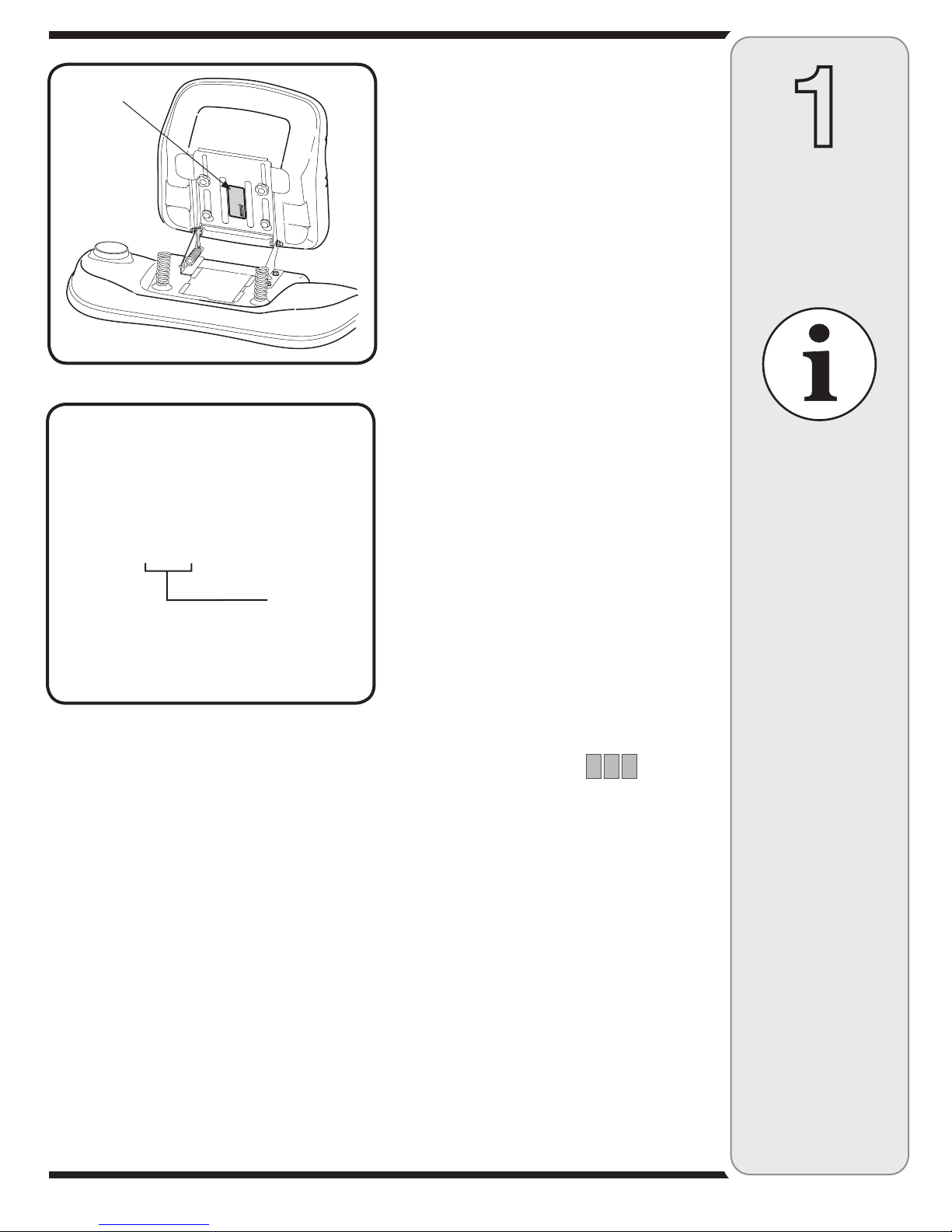
To determine which model of rider you have, you will
need to locate the rider’s model plate, located under the
seat, as in Fig. 1-1. Simply flip the seat up and locate the
model plate, which will consist of an 11 digit/letter model
number and a serial number. For ease in this installation
and for future use, copy your rider’s model number &
serial number below now:
Rider Model Number:__ __ __ __ __ __ __ __ __ __ __
Rider Serial Number:_________________________
The 5th, 6th & 7th numbers from the left in your model
number determine your rider’s model series. See Fig.
1-2.
When you fill in your model number in the space above,
the actual model series number should fall into the gray
shaded area.
Now that you have determined what model rider you are
attaching this grass bag collection system to, follow the
instructions on the following pages according to your
model of rider.
NOTE:
References to LEFT
and RIGHT indicate the
left and right sides of
the tractor when facing
forward in the operator’s
position. Reference to
the FRONT indicates the
grille end; to the REAR,
the rear end of the rider.
Figure 1-1
Figure 1-2
1 3 A M 7 9 0 G 0 0 0
Indicates Model Series 700
Sample Model Number
www
.mtdproducts
.com
MTDLLC
P
.O.BOX
361131
CLEVELAND,OH
44136
330-220-4683
800-800-7310
Model Plate

4
CONTENTS OF CARTON
Before beginning installation, remove all parts from the carton to make sure everything is present. Carton
contents are listed below and shown in Fig. 2-1.
One Chute Tube
One Discharge Chute Assembly
Two Grass Bag Assemblies
Grass Catcher Support Brackets
One Support Tube
One Grass Catcher Cover Assembly
One Mounting Bracket
*Blades (Included in 46” Bagger Kits)
2
Carton
Contents
If you are missing
any parts, please
do not contact the
retailer where you
purchased this unit,
call MTD directly at
1-330-220-4MTD or
toll free at
1-800-800-7310.
Figure 2-1
Chute Tube
Discharge Chute
Assembly
Support Tube
Mounting Bracket Assenmbly
Grass Bag Assemblies
Grass Catcher Cover
Assembly
Grass Catcher
Support Brackets
*Blades
*Included with Bagger Kits for 46” decks.

5
2
If you are missing
any parts, please
do not contact the
retailer where you
purchased this unit,
call MTD directly at
1-330-220-4MTD or
toll free at
1-800-800-7310.
NOTE:
Each item has
been identified in
above for ease of
assembly, and the
letter code assigned
here is maintained
in assembly
instructions.
(#) = Quantity
CONTENTS OF HARDWARE PACK
This grass collector kit is shipped with a hardware pack enclosed. This hardware pack may contain extra
parts for installation on a different rider from which you have. Please check your hardware pack against the
illustration below.
NOTE: Each item has been identified above for ease of assembly, and the letter code assigned here is maintained in
assembly instructions.
* The clevis pin (B1) and hairpin clip (B2) may come pre-installed in the hitch-plate assembly from the factory. In that
case it will not be included in the hardware pack, but pre-installed in the hitch-plate.
Carton
Contents
For decks with grass catcher pin
not pre-installed
Figure 2-2
A1
E2
E1
(1)
(1)
(2)
A2
(2)
B1*
(1)
B2*
(1)
C1
(2)
C2
(2)
D1
(8)
D2
(2)
(#) = Quantity

6
3
Attaching
Bracket
Assembly
Model Series 600
IMPORTANT:
Before assembly,
place the tractor on
a firm, level surface,
disengage the PTO,
stop the tractor
engine and set the
parking brake.
NOTE:
There are two holes
in the clevis pin.
Be sure to insert
the hairpin clip in
the upper hole to
properly secure the
bracket assembly to
the hitch plate.
Attaching The Bracket
Assembly
Model Series 600
IMPORTANT: Before assembly, place the tractor on
a firm, level surface, disengage the PTO, stop the
tractor engine and set the parking brake.
1. For convenience, pivot the seat forward and leave
it in that position until the grass collector is fully
mounted and assembled.
2. Position the hooked ends of the bracket assembly
over the shoulder bolts (1). Swing in the bottom of
the bracket assembly down and in (2) over the hitch
plate and aligning with the hole on the hitch plate.
See Fig. 3-1.
3. Insert the clevis pin (B1 in Fig. 2-2) through the
aligned holes in both the bracket assembly and the
hitch plate and secure with the hairpin clip (B2 in Fig.
2-2). Refer to Figure 3-2.
NOTE: There are two holes in the clevis pin. Be sure
to insert the hairpin clip in the upper hole to properly
secure the bracket assembly to the hitch plate.
Figure 3-1
Figure 3-2
Upper Hole
Hitch Plate

7
Figure 3-3
Figure 3-5
Figure 3-6
Figure 3-4
Inner holes
Upper Hole
Assembling Support
Brackets
Model Series 700
1. Locate the eight self-tapping screws supplied in your
hardware pack (D1 from Fig. 2-2). Attach the right
hand grass catcher support bracket using four of
the supplied screws in position as shown in Fig. 3-3.
Place the left hand grass catcher support bracket in
position and secure with the other four screws.
NOTE: For easier installation, first align and start all
four screws in each bracket before tightening.
2. Insert a hex bolt (C1 in Fig. 2-2) through a shoulder
spacer, (C2 in Fig. 2-2), and secure with a 3/8” Hex
FlangeLock Nut (D2 in Fig. 2-2). Tighten securely.
Repeat on other side.
NOTE: If the grass collection system is removed for
any reason, it is not necessary to remove the support
brackets from the tractor.
Attaching The Bracket
Assembly
1. Remove the two nuts and screws on each side of
the mounting bracket holding the hitch plate.
See Fig. 3-4.
NOTE: The clevis pin and hairpin clip may come pre-
installed in the hitch-plate from the factory. If this is the
case, remove the clevis pin now by removing the hairpin
clip and lifitng the clevis pin out as seen in Fig. 3-4.
2. Rotate the hitch plate 180° from its original position.
Re-insert the four bolts through mounting bracket
and hitch plate frame and secure with nuts removed
earlier. Use the inner holes (closest to the mounting
hooks) on the mounting bracket. Refer to Fig. 3-5.
3. Position the hooked ends of the mounting bracket
assembly to the outside of the support bracket and
over the shoulder bolts on both sides. Secure each
mounting bracket with a clevis pin (A1 from Fig. 2-2)
and hairpin clip (A2 from Fig. 2-2) from the hardware
pack. See Fig. 3-6.
4. Insert the clevis pin (B1 in Fig. 2-2) through the
aligned holes in both the bracket assembly and the
hitch plate and secure with the hairpin clip (B2 in
Fig. 2-2). See Fig. 3-6.
IMPORTANT: There are two holes in the clevis pin.
Be sure to insert the hairpin clip in the upper hole
to properly secure the bracket assembly to the
hitch plate.
3
Attaching
Support
Bracket &
Bracket
Assembly
Model Series 700
NOTE:
If the grass
collection system
is removed for any
reason, it is not
necessary to remove
the support brackets
from the tractor.
The clevis pin and
hairpin clip may
come pre-installed in
the hitch-plate from
the factory. If this
is the case, remove
the clevis pin now by
removing the hairpin
clip and lifitng the
clevis pin out.
IMPORTANT:
There are two holes
in the clevis pin.
Be sure to insert
the hairpin clip in
the upper hole to
properly secure the
bracket assembly to
the hitch plate.

8
Attaching Grass Bags &
Grass Bag Cover
1. Place the support tube in position on the rear of unit
by sliding the support tube down through the holes in
the left side of the bracket assembly. Use the inside
hole on the bracket assembly regardless of what size
deck your tractor is equipped with. Refer to Fig. 4-1.
2. Attach the grass bags by hooking them onto the grass
bag bracket using the slots in the grass bag and the
tabs on the grass bag bracket as shown in Fig. 4-2.
3. Remove both clevis pins, belleville washers and
hairpin clips from the hinges of the grassbag cover.
4. Place the grass bag cover on top of the grass bags
and align the holes on the hinges of the grass bag
cover with the corresponding holes on the support
tube assembly. See Fig. 4-3.
5. Reinsert the clevis pins previously removed through
the hinge on the support tube assembly and then
through the grass bag cover. See Fig. 4-4.
6. Secure with belleville washer and hairpin clip with the
crown side of the washer going against the hairpin
clip. See inset images in Fig. 4-4.
7. Repeat with the second set of hardware through the
second hinge of the grass bag and the tube assembly
from the opposite direction.
NOTE: Insert the clevis pins from the outside in as
shown in the inset images of Figure 4-4.
NOTE: It is very important to maintain this order and
direction while installing these hardware pieces. After
installation, make sure that the grass bag cover pivots on
the support tube and opens.
4
NOTE:
Insert the clevis pins
from the outside in
as shown in the inset
images of Fig. 4-4.
NOTE:
It is very important to
maintain this order and
direction while installing
these hardware pieces.
After installation, make
sure that the grass bag
cover pivots on the sup-
port tube and opens.
Attaching
Grass Bags
& Grass Bag
Cover
All Model Series
600 & 700
Figure 4-2
Figure 4-3
Figure 4-4
Figure 4-1
Inside Hole

9
5
NOTE:
If your tractor is
equipped with a 46”
cutting deck, three
2-in-1 cutting blades
are included with
this kit. For proper
bagging performance,
install these blades on
your tractor using the
following instructions.
NOTE:
The hex flange nut
has a normal (right-
handed) thread
pattern. Do NOT
attempt to force the
nut in the incorrect
direction. Doing so
may damage the
nut and create a
safety hazard.
Attaching
The Blades
46-Inch Cutting
Deck Models Only
Attaching The Blades
NOTE: If your tractor is equipped with a 46” cutting deck,
three 2-in-1 cutting blades are included with this kit. For
improved bagging performance, install these blades on
your tractor using the following instructions.
Remove the blades from your tractor’s cutting deck as
follows:
1. Remove the cutting deck from beneath the tractor,
(refer to Deck Removal in the MAINTENANCE
section of your tractor’s operator’s manual for detailed
instructions) then gently flip the deck over to expose
its underside.
2. Place a block of wood between the center deck hous-
ing baffle and the cutting blade to act as a stabilizer,
keeping the blades from turning when you loosen the
hex flange nuts.
3. Use a 15/16” wrench to remove the hex flange nut that
secures the blade to the spindle assembly.
NOTE: The hex flange nut has a normal (right-handed)
thread pattern. Do NOT attempt to force the nut in the
incorrect direction. Doing so may damage the nut and
create a safety hazard.
4. Install the new blades packed with the bagger. Be
sure to install the blade with the side of the blade
marked ‘‘Bottom’’ (or with a part number stamped in
it) facing the ground when the rider is in the operating
position.
5. Mount the SMALLER of the three blades to the
CENTER spindle. The remaining two blades are
interchangeable. See Fig. 5-1.
6. Use a torque wrench to tighten the blade spindle hex
flange nut to between 70 and 90 foot-pounds.
7. Remount the cutting deck.
Figure 5-1
Smaller Blade
Part No. 742-0645
Larger Blades
Part No. 742-0644
Hex Flange Nut

10
Attaching Discharge
Chute
1. On some older models, a clip is already installed on
the cutting deck next to the discharge chute opening
in position A, B, or C, as seen in Fig. 6-1. If this is
the case, the clip must be removed and a grass
catcher pin installed.
2. Pin Installation: A grass catcher pin (E1 in Fig. 2-2)
and nut (E2 in Fig. 2-2) have been supplied in the
hardware pack. First remove the clip (if present),
as seen in Fig. 6-2A, by removing the nut and bolt.
Then attach the grass catcher pin as seen in Fig.
6-2B. Make sure to secure the pin tightly.
3. Some units may not have clip, but will have an open
hole for pin installation. In this case, install the grass
catcher pin from the hardware pack in the available
hole.
4. You will then need to position the retainer strap on
the discharge chute to correspond with the hole and
pin. See Fig. 6-3 for retainer strap positioning.
NOTE: The retainer strap is fitted at position A on the
discharge chute. However, on older models of trac-
tors, you will have to change the position of the strap
depending on the location of the grass catcher pin on
the deck. Remove the retainer strap from position A on
the discharge chute to position B or C corresponding to
the position of the grass catcher pin at A, B or C on the
deck. See Fig. 6-3.
Figure 6-1
Figure 6-3
6
Attaching
Discharge
Chute
All Model Series
NOTE:
The retainer strap is
fitted at position A on
the discharge chute.
However, on older
models of tractors,
you will have to
change the position
of the strap depend-
ing on the location of
the grass catcher pin
on the deck. Remove
the retainer strap
from position A on
the discharge chute
to position B or C
corresponding to the
position of the grass
catcher pin at A, B or
C on the deck. See
Fig. 6-3.
Figure 6-2
AB
Discharge Chute

11
Figure 6-4
Figure 6-5
Figure 6-6
NOTE:
When both grass
bags are full, place
the tractor on a
firm, level surface,
disengage the PTO,
turn the tractor
engine off and set
the parking brake.
6
Attaching
Discharge
Chute
All Model Series
Attaching Discharge
Chute
All Model Series
1. Raise the deck to its highest position.
2. Raise the chute deflector on the deck and hold it
while you position the discharge chute over the
chute opening.
3. Place the top rear edge of the discharge chute over
the top rear edge of the chute opening.
4. Push down on the discharge chute so that its front
bottom edge rolls around the bottom of the deck,
then slide the chute forward to the stop on the deck.
See Fig. 6-4.
5. Lock the discharge chute in position by hooking
the retainer strap over the grass catcher pin on the
deck. See Fig. 6-4.
6. Insert the curved end of chute tube into the hole in
the grass bag cover. See Fig. 6-5.
7. Place the lower end of the chute tube over the
discharge chute so that the tabs on the discharge
chute fits into the pockets on the chute tube. See
Fig. 6-6.
8. Secure by hooking the two retainer straps of the
discharge chute to the pins on the chute tube. See
Fig. 6-6.
Bagger Usage
All Model Series
NOTE: When both grass bags are full, place the tractor
on a firm, level surface, disengage the PTO, turn the
tractor engine off and set the parking brake.
1. Flip Seat up.
2. Lift up grass bag cover. Do not remove the chute
tube assembly from the tractor.
3. Remove the grass bags by lifting these up and mov-
ing the bags away from the support tube assembly.
4. Empty the grass clippings at a proper disposal sight,
use the handle at the bottom of each grass bag.
Holding the bag firmly, empty the contents
5. Replace grass bags, close lid, flip down seat, restart
your tractor and resume cutting your grass.
Grass Catcher Pin
Retainer Strap
Tab
Pocket

12
19
22
11
18
13
13
13
20
22
13
22
11
18
18
49
4
24
6
25
14 17
7
23
6
10
8
1
42
46
37
5
29
45
47
41
39
26
2
8
34
33
35
36
32
32
27
11
13
28
50
13
For Deck
12
21
17
38
48
43
40
15
44
3
30
15
16
9
31
31
33

13
7
REF
NO.
PART
NUMBER
DESCRIPTION
1 16587D Support Bracket: Bagger
2 16592 Support Tube Assembly
3 664-04017 Grass catcher Cover Assy.
(includes Ref. 37 - 48)
4 710-0597 Screw 1/4-20 x 1”
5 710-0751 Hex Head Screw 1/4-20 x .62
6 710-1260A Self-Tap. Screw 5/16-18 x .75
7 710-3005 Hex Hd. Screw, 3/8-16 x 1.25
8 710-3008 Hex Hd. Screw, 5/16-18 x .75
9 711-0309A Clevis Pin, .62 Dia.
10 711-0310 Clevis Pin, .50 x 1.18
11 711-04069 Grass Catcher Pin 1/4-20
12 711-1421 Clevis Pin, 3/8 x .75
13 712-04064 Hex Flange Lock Nut, 1/4-20
14 712-04065 Hex Flange Lock Nut, 3/8-16
15 712-3004A Hex Flg. Lock Nut, 5/16-18
16 714-0117 Hairpin Clip
17 714-0145 Click Pin
18 723-04008A Chute Strap
19 731-04153 Discharge Chute 38”/42” Dk.
731-04159 Discharge Chute 46” Deck
20 731-0899E Chute Tube 38”/42” Deck
731-0926B Chute Tube 46” Deck
21 736-0331 Bell Washer
22 736-3092 Flat Washer
23 738-04058 Shoulder Spacer
24 783-04919 Mounting Bracket, LH
For parts and/or
accessories
please call
1-800-800-7310, or
1-330-220-4683.
www.mtdproducts.com
Part List:
Rear Twin
Bagger
REF
NO.
PART
NUMBER
DESCRIPTION
25 783-04968 Mounting Bracket, RH
26 783-0601 Mounting Bracket
27 783-0673B Mounting Bracket RH
28 783-0764B Mounting Bracket LH
29 783-0765 Bracket: Cross Support
30 764-0221 Catcher Bag Assembly
(Includes Ref. 31 - 36)
31 16591A Bag Hanger Bracket
32 710-0473 Machine Screw, , #10-24 x .5
33 710-0604A Self-tap. Scr., 5/16-18 x .625
34 712-0272 Hex Sems Nut, #10-24
35 749-0701A Grass Bag Frame
36 764-0221 Grass Catcher Bag
37 16595B Screen Mounting Bracket
38 16596 Hinge Assembly
39 710-1652 Self-Tap. Screw 1/4-20 x .625
40 720-04017 Grass catcher Sceen
41 726-0233 Push Nut, .25 x .50
42 726-0258 Zip Twist Fastener
43 728-0123 Pop Rivet, 3/16 x .450
44 731-04167 Double Grassbag Cover
45 731-04189 Grassbag Hopper Seal
46 731-0824A Plastic Plate, 1/8 x 5.6
47 735-04020 Grassbag Hopper Seal
48 736-0400 Flat Washer, .194 x .62 x .063
49 742-0644* 2-in-1 Blade 16.28” 46” Deck
50 742-0645* 2-in-1 Blade 14.88” 46” Deck
* Blades included with 46” cutting deck bagger kits only!

Al propietario • Contenido de la caja • Ensamblado • Listados de piezas • Garantía
MTD LLC. APARTADO POSTAL 361131 CLEVELAND, OHIO 44136-0019
IMPRESO EN ESTADOS
UNIDOS DE AMÉRICA
LEA CON ATENCIÓN LAS REGLAS DE SEGURIDAD E INSTRUCCIONES ANTES DE OPERAR
LA UNIDAD
IMPORTANTE
MANUAL DEL OPERADOR
Modelos 190-180 & 190-182
Kit de embolsado posterior
doble

15
Búsqueda y registro del número de modelo
ANTES DE COMENZAR A MONTAR SU NUEVO EQUIPO,
por favor ubique la placa de modelo y copie la información de la misma en el Manual de Operador para referencia futura. La
información contenida en la placa del modelo es muy importante en caso de necesitar ayuda de nuestro Departamento de
Asistencia al Cliente o del distribuidor autorizado.
Puede ubicar la misma mirando en la parte delantera, lado izquierdo, de la cubierta de la tolva plástica para recorte de césped,
según se muestra a continuación:
Este Manual del Operador es una parte importante de su nuevo colector de césped. Le ayudará a
montar, preparar y mantener la unidad para obtener los mejores resultados. Por favor, lea y com-
prenda el contenido del manual.
Por favor, NO devuelva la unidad al minorista a quien se la adquirió sin ponerse en contacto
primero con el Departamento de Asistencia al Cliente.
Asistencia al cliente
En caso de tener problemas para montar este producto o de tener dudas con respecto a los controles, funcionamiento o
mantenimiento del mismo, puede solicitar la ayuda de expertos. Elija entre las opciones que se presentan a continuación:
• Visite mtdproducts.com. Haga clic en la opción Service & Support (Servicio y Asistencia) del menú.
• Comuníquese por teléfono con un Representante de Asistencia al Cliente al 1-800 -800-7310.
• Por favor tenga a mano el número de modelo y el número de serie de su unidad cuando llame. Consulte la sección
anterior para obtener esta información. Se le solicitará que ingrese el número de serie para poder procesar su llamada.
*Ubique la placa de modelo en su embolsadora y copie la información de la misma en el espacio provisto más arriba para referencia futura
Número de modelo Número de serie

16
1
Identificación
delmodelo
depodadora
tractor
Colector de césped
FastAttach™ con
sistema de bolsa doble
Este Modelo 190-180 & 190-182 Coleccionista de Hierba
de Bolso de Gemelo es un sistema de colección de
hierba diseñado para el uso en todo MTD 38”, 42” & 46”
tractores.
Las instrucciones de este manual se dividen en sec-
ciones. Lea con atención todas las secciones y estudie
las ilustraciones para asegurar una adecuada instalación
y uso de este aditamento. Lea y observe todas las
declaraciones de ADVERTENCIA y PRECAUCIÓN. Se
las ha incluido para proporcionar protección al instalador
y al usuario del equipo, y para asegurar una prolongada
vida de servicio del equipamiento.
NOTA: Las referencias relativas a los lados IZQUIERDO
y DERECHO indican los lados izquierdo y derecho del
tractor mirando hacia adelante desde la posición del
operador. La referencia al FRENTE indica el extremo
de la parrilla; la referencia al lado POSTERIOR indica el
extremo trasero del tractor.
Determine el modelo
de la podadora tractor
Como este manual ha sido diseñado para la instalación
de la nueva embolsadora en diversas unidades de
podadora tractor, es importante que determine cuál es
el modelo de podadora tractor que usted posee. De
ese modo usted sabrá cuál es el grupo de las siguientes
instrucciones que deberá observar.
Para determinar cuál es el modelo de podadora tractor
que usted posee, será necesario que ubique la placa de
modelo de la podadora tractor que se encuentra debajo
del asiento. Simplemente levante el asiento y ubique
la placa de modelo, la cual comprende un número de
modelo de 11 dígitos/ letras y un número de serie. Para
facilitar la instalación y para uso futuro, copie el número
de modelo y el número de serie de la podadora tractor a
continuación:
Tractor modelo númeror:__ __ __ __ __ __ __ __ __ __ __
Podadora tractor serie número:___________________
Los números 5º, 6º y 7º de la izquierda en el número
de modelo determinan la serie del modelo de podadora
tractor. Vea la Fig. 1-2.
Cuando complete el número de modelo en el espacio
que se suministra más arriba, el número de serie
concreto del modelo debe quedar en el área sombreada
en gris.
Ahora que ha determinado cuál es el modelo de
podadora a la cual usted va a adosar este sistema de
recolección de pasto, observe las instrucciones de
las siguientes páginas de acuerdo con el modelo de
podadora tractor que posee.
NOTA: Las referencias
relativas a los lados
IZQUIERDO y DERECHO
indican los lados izqui-
erdo y derecho del tractor
mirando hacia adelante
desde la posición del
operador. La referencia al
FRENTE indica el extremo
de la parrilla; la referen-
cia al lado POSTERIOR
indica el extremo trasero
del tractor.
Figura 1-1
Figura 1-2
Placa de modelo
Número de Modelo de Muestra
Indica Serie Modela 600
1 3 A M 6 1 9 G 0 0 0

17
CONTENIDO DE CARTÓN
Antes de la instalación que comienza, quite todas las partes del cartón para asegurarse que todo está
presente. Los contenido de cartón son puestos en una lista abajo y mostrados en la Figura 2-1.
Un Tubo de Tolva
Una Asamblea de Tolva de Descarga
Dos Asambleas de Bolso de Hierba
Escuadras de Soporte de Receptor de Hierba
Un Tubo de Tolva
Una Asamblea de Tolva de Descarga
Dos Asambleas de Bolso de Hierba
*Láminas (Incluido con equipos bagger para 46” Cubiertas)
2
Figura 2-1
Tubo de Tolva
Tolva de Descarga
Asamblea
Tubo de Apoyo
Soporte de montaje
Asambleas de Bolso de Hierba
Receptor de Hierba Cubre
Asamblea Si le faltan piezas,
por favor, no contacte
al minorista a quien
usted adquirió
la unidad. Llame
directamente a MTD
al 1-330-220-4MTD
o comuníquese de
forma gratuita al
1-800-800-7310
Contenido
de la caja
Escuadras de Soporte
de Receptor de Hierba
*Láminas

18
2CONTENIDO DE PAQUETE DE HARDWARE
Este equipo de coleccionista de hierba es transportado con un paquete de hardware encerrado. Este
paquete de hardware puede contener extra partes para la instalación en un jinete diferente del cual usted
tiene. Por favor compruebe su paquete de hardware contra la ilustración abajo.
Para cubiertas con alfiler de receptor
de hierba no preinstalado
Figura 2-2
Si le faltan piezas,
por favor, no contacte
al minorista a quien
usted adquirió
la unidad. Llame
directamente a MTD
al 1-330-220-4MTD
o comuníquese de
forma gratuita al
1-800-800-7310
NOTA:
Para facilitar el
ensamblado se ha
identificado cada
uno de los elementos
mencionados arriba,
y el código de letra
aquí asignado se
mantiene en las
instrucciones para
el ensamblado.
Contenido
de la caja
NOTA: Para facilitar el ensamblado se ha identificado cada uno de los elementos mencionados arriba, y el código de
letra aquí asignado se mantiene en las instrucciones para el ensamblado.
* El alfiler de clevis (B1) y clip de horquilla (B2) puede venir preinstalado a la asamblea de plato de tirón de la fábrica.
En esto caso no será incluido en el paquete de hardware, pero preinstalado en el plato de tirón.
(#) = Cantidad
A1
E2
E1
(1)
(1)
(2)
A2
(2)
B1*
(1)
B2*
(1)
C1
(2)
C2
(2)
D1
(8)
D2
(2)

19
3
Instalación
Conjunto de
soporte
Modelos Series 600
IMPORTANTE:
Antes del ensamblado,
coloque el tractor sobre
una superficie firme y
nivelada, desenganche
la toma de fuerza (PTO),
detenga el motor del
tractor y coloque el freno
de estacionamiento.
IMPORTANTE:
Hay dos orificios en el
pasador de horquilla.
Asegúrese de insertar el
broche de horquilla en
el orificio superior para
fijar adecuadamente el
conjunto del soporte a la
placa de enganche.
Instalación
Conjunto de soporte
Modelos series 600
IMPORTANTE: Antes del ensamblado, coloque el
tractor sobre una superficie firme y nivelada, desen-
ganche la toma de fuerza (PTO), detenga el motor
del tractor y coloque el freno de estacionamiento.
1. Para mayor comodidad, gire el asiento hacia adelante
y déjelo en esa posición hasta que el colector de
pasto esté totalmente colocado y ensamblado.
2. Coloque los extremos enganchados del conjunto del
soporte por encima de los pernos con reborde (1).
Gire hacia adentro la parte inferior del conjunto del
soporte hacia abajo y hacia adentro (2) por encima
de la placa de enganche y alinéela con el orificio de
la placa de enganche. Vea la Figura 3-1.
3. Inserte el pasador de horquilla (B-1 en el Higo 2-2)
a través de los orificios alineados en el conjunto del
soporte y en la placa de enganche y ajústelo con el
broche de horquilla (B1 en el Higo 2-2). Consulte la
Figura 3-2.
IMPORTANTE: Hay dos orificios en el pasador de
horquilla. Asegúrese de insertar el broche de horquilla
en el orificio superior para fijar adecuadamente el
conjunto del soporte a la placa de enganche.
Figura 3-1
Figura 3-2
Orificio superior
Placa de
enganche

20
3
Instalación
del soporte
y del
conjunto del
soporte
Modelo Serie 700
NOTA:
Si el sistema de recogida
de pasto se retira por
alguna razón, no es
necesario retirar los
soportes del tractor
IMPORTANTE:
Hay dos orificios en el
pasador de horquilla.
Asegúrese de insertar el
broche de horquilla en
el orificio superior para
fijar adecuadamente el
conjunto del soporte a la
placa de enganche.
Figura 3-3
Figura 3-5
Figura 3-6
Figura 3-4
Orificios interiores
Orificio
superior
Ensamblado de los
soportes
Modelo Serie 700
1. Localice los ocho tornillos de autogolpeado suminis-
trados en su paquete de hardware (D1 del Higo 2-2).
Ate la escuadra de soporte de receptor de hierba
de mano derecha usando cuatro de los tornillos
suministrados en la posición como mostrado en el
Higo 3-3. Coloque la escuadra de soporte de receptor
de hierba de mano izquierda en la posición y seguro
con los otros cuatro tornillos.
NOTE: Para la instalación más fácil, primero alinee y
comience cuatro tornillos en cada soporte antes del
apretamiento.
2. Inserte un cerrojo de maleficio (C1 en el Higo 2-2)
por un espaciador de hombro, (C2 en el Higo 2-2), y
seguro con un 3/8” Encantan la Tuerca FlangeLock
(D2 en el Higo 2-2). Apriétese bien. Repita en otro
lado.
NOTA: Si el sistema de recogida de pasto se retira por
alguna razón, no es necesario retirar los soportes del tractor
Instalación del conjunto
del soporte
1. Retire las dos tuercas y tornillos que hay a cada
lado del soporte de montaje que sujeta la placa de
enganche. Vea la Figura 3-4.
NOTE: el alfiler de clevis y el clip de horquilla pueden
venir preinstalados al plato de tirón de la fábrica. Si es así,
quite el alfiler de clevis ahora quitando el clip de horquilla y
lifitng el alfiler de clevis como visto en el Higo 3-4.
2. Rote la placa de enganche 180º desde su posición
original. Reinserte los cuatro pernos a través del so-
porte de montaje y el marco de la placa de enganche
y fíjelos con las tuercas retiradas antes. Use los
orificios interiores (los más cercanos a los ganchos
de montaje) del soporte de montaje. Consulte la
Figura 3-5.
3. Coloque los finales aquilinos de la asamblea de
soporte de montaje al exterior de la escuadra de
soporte y sobre los cerrojos de hombro a ambos
lados. Asegure cada soporte de montaje con un alfiler
de clevis (A1 del Higo 2-2) y clip de horquilla (A2 del
Higo 2-2) del paquete de hardware. Ver el Higo 3-6.
4. Insertar el alfiler de clevis (B1 en el Higo 2-2) por los
agujeros alineados tanto en la asamblea de soporte
como en el plato de tirón y seguro con el clip de
horquilla (B2 en el Higo 2-2). Ver el Higo 3-6.
IMPORTANTE: Hay dos orificios en el pasador de
horquilla. Asegúrese de insertar el broche de horquilla en
el orificio superior para fijar adecuadamente el conjunto
del soporte a la placa de enganche.
Other manuals for 190-182
2
Table of contents
Languages:
Other MTD Lawn Mower Accessories manuals

MTD
MTD 19A30050100 Assembly instructions

MTD
MTD OEM-190-821 User manual

MTD
MTD OEM-190-821 User manual

MTD
MTD OEM-190-841 User manual

MTD
MTD 19A40002OEM User manual

MTD
MTD Cub Cadet 19B70004100 User manual

MTD
MTD 19A30013OEM User manual

MTD
MTD 19B30031OEM User manual

MTD
MTD 13AAB11CH712 User manual

MTD
MTD OEM-190-182 User manual
Popular Lawn Mower Accessories manuals by other brands

Husqvarna
Husqvarna 968 999732 parts manual

Craftsman
Craftsman 917.248940 owner's manual

Simplicity
Simplicity 990194 Instructions and parts list

Toro
Toro 02920 installation instructions

ARNOLD
ARNOLD XTREME Craftsman 532138971 installation instructions

Dixon
Dixon SpeedZTR 539 131354 Operator and parts manual