MTD 19A70043OEM User manual

MTD LLC, P.O. BOX 361131 CLEVELAND, OHIO 44136-0019
Printed In USA
WARNING
READ AND FOLLOW ALL SAFETY RULES AND INSTRUCTIONS IN THIS MANUAL
BEFORE ATTEMPTING TO OPERATE THIS MACHINE.
FAILURE TO COMPLY WITH THESE INSTRUCTIONS MAY RESULT IN PERSONAL INJURY.
OperatOr’sManual
Twin Rear Bagger — Model No. 19A70043OEM
(January 20, 2015)
Form No. 769-10572

To The Owner 1
2
Thank you for purchasing a bagging attachment manufactured
by MTD LLC. It was carefully engineered to provide excellent
performance when properly operated and maintained.
Please read this entire manual prior to operating the equipment.
It instructs you how to safely and easily set up, operate and
maintain this attachment. Please be sure that you, and any
other persons who will operate the machine, carefully follow the
recommended safety practices at all times. Failure to do so could
result in personal injury or property damage.
All information in this manual is relative to the most recent
product information available at the time of printing. Review this
manual frequently to familiarize yourself with the attachment,
its features and operation. Please be aware that this Operator’s
Manual may cover a range of product specifications for various
models. Characteristics and features discussed and/or illustrated
in this manual may not be applicable to all models. MTD LLC
reserves the right to change product specifications, designs and
equipment without notice and without incurring obligation.
If you have any problems or questions concerning this
attachment, phone your local authorized MTD service dealer
or contact us directly. MTD’s Customer Support telephone
numbers, website address and mailing address can be found on
this page. We want to ensure your complete satisfaction at all
times.
Throughout this manual, all references to right and left side of the
machine are observed from the operating position
Thank You
Customer Support
Please do NOT return the machine to the retailer or dealer without first contacting our Customer Support Department.
If you have difficulty assembling this product or have any questions regarding the controls, operation, or maintenance of
this machine, you can seek help from the experts. Choose from the options below:
◊ Visit us on the web at www.mtdproducts.com
◊ Call a Customer Support Representative at (800) 800-7310 or (330) 220-4683
◊ Write us at MTD LLC • P.O. Box 361131 • Cleveland, OH • 44136-0019
Record Product Information
Before setting up and operating your new equipment, please
locate the model plate on the equipment and record the
information in the provided area to the right. You can locate the
model plate by looking at the topside of the bagger cover. This
information will be necessary, should you seek technical support
via our web site, Customer Support Department, or with a local
authorized service dealer.
Model NuMber
Serial NuMber
Safe Operation Practices ........................................ 3
Carton Contents & Hardware Packs...................... 6
Assembly & Installation.......................................... 8
Operation................................................................16
Parts List..................................................................18
Warranty..................................................Back Cover
Table of Contents

Important Safe Operation Practices 2
3
General Operation
1. Read, understand, and follow all instructions on your
equipment and in their manuals before attempting to
assemble and operate. Keep this manual in a safe place for
future and regular reference and for ordering replacement
parts.
2. To help avoid blade contact or a thrown object injury, keep
bystanders, helpers, children and pets at least 75 feet from
the mower while it is in operation. Stop machine if anyone
enters the area.
3. Thoroughly inspect the area where the equipment is to be
used. Remove all stones, sticks, wire, bones, toys, and other
foreign objects which could be picked up and thrown by
the blade(s). Thrown objects can cause serious personal
injury.
4. Always wear safety glasses or safety goggles during
operation and while performing an adjustment or repair
to protect your eyes. Thrown objects which ricochet can
cause serious injury to the eyes.
5. Do not operate the mower without the discharge cover
or entire grass catcher in its proper place. A missing
or damaged discharge cover or grass bag attachment
component may result in thrown objects or blade contact
injuries.
6. Do not put hands or feet near rotating parts or under the
cutting deck. Contact with the blade(s) can amputate
hands and feet.
7. Shut off mower’s engine and wait for blades to come to
a complete stop before unclogging mower’s discharge
opening or bagger parts.
8. Slow down before turning. Operate the machine smoothly.
Avoid erratic operation and excessive speed. Be aware
that a grass catcher attachment can affect the handling
characteristics of your mower.
9. Disengage blade(s), set parking brake, stop engine and wait
until the blade(s) come to a complete stop before opening
bagger attachment’s top cover, removing grass catcher,
emptying grass, unclogging chute, removing any grass or
debris, or making any adjustments.
10. Never leave a running machine unattended. Always turn
off blade(s), place transmission in neutral, set parking
brake, stop engine and remove key before dismounting.
11. Your machine is designed to cut normal residential grass of
a height no more than 10”. Do not attempt to mow through
unusually tall, dry grass (e.g., pasture) or piles of dry leaves.
Dry grass or leaves may contact the engine exhaust and/
or build up on the mower deck presenting a potential fire
hazard.
12. If situations occur which are not covered in this manual, use
care and good judgment. Contact your customer service
representative for assistance.
Slope Operation
Slopes are a major factor related to loss of control and tip-over
accidents which can result in severe injury or death. Attachments
can also affect the stability of the machine. All slopes require
extra caution.
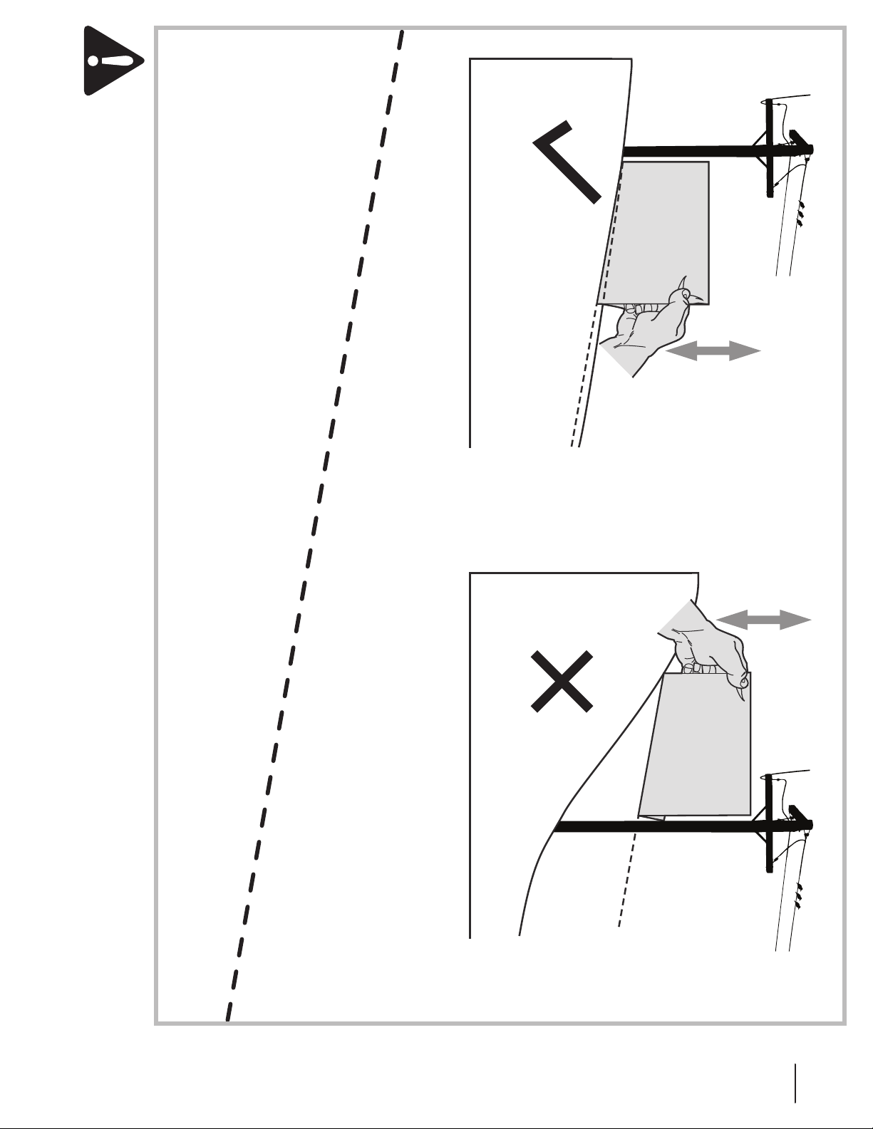
For your safety, use the slope gauge included as part of this
manual to estimate the angle of slopes before operating this
machine on a sloped or hilly area. If the slope is greater than 10
degrees as shown on the slope gauge, do not operate the mower
with the grass bag attachment installed on that area or serious
injury could result.
Do:
1. Mow up and down slopes, not across. Exercise extreme
caution when changing direction on slopes.
2. Watch for holes, ruts, bumps, rocks, or other hidden
objects. Uneven terrain could overturn the machine. Tall
grass can hide obstacles.
WARNING! This symbol points out important safety instructions which, if not followed,
could endanger the personal safety and/or property of yourself and others. Read and follow
all instructions in this manual before attempting to operate this machine. Failure to comply
with these instructions may result in personal injury.
When you see this symbol. HEED ITS WARNING!
DANGER! This attachment was built to be used according to the safe operation practices in
this manual. Carelessness or error on the part of the operator can result in serious injury.
Mowers are capable of amputating hands and feet and throwing objects. Failure to observe
the following safety instructions as well as the instructions provided with your mower, could
result in serious injury or death.

4Section 2 — important Safe operation practiceS
Safety Symbols
This table depicts and describes safety symbols that may appear on this product. Read, understand, and follow all instructions on the
machine before attempting to assemble and operate.
Symbol Description
READ THE OPERATOR’S MANUAL(S)
Read, understand, and follow all instructions in the manual(s) before attempting to
assemble and operate
STOP
Turn off the engine before opening the bagger cover.
3. Use slow speed. Choose a low enough speed setting so
that you will not have to stop or shift while on the slope.
Tires may lose traction on slopes even though the brakes
are functioning properly. Always keep machine in gear
when going down slopes to take advantage of engine
braking action.
4. Follow the manufacturer’s recommendations for wheel
weights or counterweights to improve stability.
5. Keep all movement on the slopes slow and gradual. Do
not make sudden changes in speed or direction. Rapid
engagement or braking could cause the front of the
machine to lift and rapidly flip over backwards which could
cause serious injury.
6. Avoid starting or stopping on a slope. If tires lose traction,
disengage the blade(s) and proceed slowly straight down
the slope.
Do Not:
1. Do not turn on slopes unless necessary; then, turn slowly
and gradually downhill, if possible.
2. Do not mow near drop-offs, ditches or embankments. The
mower could suddenly turn over if a wheel is over the edge
of a cliff, ditch, or if an edge caves in.
3. Do not try to stabilize the machine by putting your foot on
the ground.
4. Do not use a grass catcher on steep slopes.
5. Do not mow on wet grass. Reduced traction could cause
sliding.
General Service
1. Before cleaning, repairing, or inspecting, make certain the
blade(s) and all moving parts have stopped. Disconnect the
spark plug wire and ground against the engine to prevent
unintended starting.
2. Keep all nuts, bolts, and screws tight to be sure the
equipment is in safe working condition.
3. Never tamper with your mower’s safety interlock system
or other safety devices. Check their proper operation
regularly.
4. Never attempt to make adjustments or repairs while the
mower’s engine is running.
5. Grass catcher components and the discharge cover are
subject to wear and damage which could expose moving
parts or allow objects to be thrown. For safety protection,
frequently check components and replace immediately
with original equipment manufacturer’s (O.E.M.) parts only,
listed in this manual. Use of parts which do not meet the
original equipment specifications may lead to improper
performance and compromise safety!
6. Maintain or replace safety and instruction labels, as
necessary.
WARNING! Your Responsibility—Restrict the use of this power machine to persons who read, understand and
follow the warnings and instructions in this manual and on the machine.
SAVE THESE INSTRUCTIONS!

5Section 2 — important Safe operation practiceS
(OK) (TOO STEEP)
USE THIS SLOPE GAUGE TO DETERMINE
IF A SLOPE IS TOO STEEP FOR SAFE OPERATION!
To check the slope, proceed as follows:
1. Remove this page and fold along the dashed line.
2. Locate a vertical object on or behind the slope (e.g. a pole, building, fence, tree, etc.)
3. Align either side of the slope gauge with the object (See Figure 1 and Figure 2 ).
4. Adjust gauge up or down until the left corner touches the slope (See Figure 1 and Figure 2).
5. If there is a gap below the gauge, the slope is too steep for safe operation (See Figure 2 above).
10° dashed line
Slope Gauge
Figure 2Figure 1
10° Slope
10° Slope
WARNING! Slopes are a major factor related to tip-over and roll-over accidents which can result in severe injury or death.
Do not operate machine on slopes in excess of 10 degrees. All slopes require extra caution. If you cannot back up the slope
or if you feel uneasy on it, do not mow it. Always mow up and down slopes, never across the face of slopes.

Contents of Carton 3
6
Before beginning installation, remove all parts from the carton to make sure everything is present. Carton contents are listed below
and shown in Fig. 3-1. The four hardware packs included in this kit are detailed on this and the following page.
• Two Adhesive Foam Strips
• Grass Catcher Cover
• Chute Tube Extension
• Flexible Tube Extension
• Upper Chute Tube
• Two Grass Bag Assemblies
• Bag Support Assembly
• Hinge Cover Pin
• Upright Support
• Chute Discharge Bracket
• Hitch Bracket Kit (5 Pcs.: 2 side & 1 cross mount, 2 wt. mounts)
• Upper Chute Support
• Discharge Chute Elbow
• Weight Bar
• Mounting Bracket Kit (Not needed for this installation)
• Four Hardware Packs (Detailed below and on the next page)
Hardware Pack
689-00341
These mounting brackets not
needed for this installation
Figure 3-1

7Section 3 — contentS of carton
CONTENTS OF HARDWARE PACK
This grass collector kit is shipped with three loose hardware packs enclosed and one set of hardware packed with the upright mounting
bracket. Please check your hardware packs against the illustrations below. The quantities for each item is listed in parenthesis.

Assembly & Installation 4
8
Figure 4-2
2. Secure the mounting bracket assembly to the tractor using
two 911-0310 clevis pins and 914-04023 cotter pins from
hardware pack 689-00320. See Figure 4-3.
Figure 4-3
3. Tighten all of the hardware installed at this time.
4. Install the upright support bracket onto the mounting
assembly on the tractor by hooking it over the mounting
assembly as shown in Figure 4-4.
NOTE: References to left, right, front and rear of the tractor are
from the operator’s position, unless otherwise stated.
• Before assembly, place the tractor on a firm, level surface,
disengage the PTO, stop the tractor engine and set the
parking brake.
Assemble Mounting Brackets
To assemble the bagger mounting assembly, locate the
mounting assembly parts, as shown in Figure 4-1, and follow
these steps:
1. Attach the two hitch side brackets to the rear attachment
bracket using four 710-0276 carriage bolts and 712-04063
flange lock nuts from hardware pack 689-00320. See Figure
4-1.
Figure 4-1
Note: When assembling this mounting assembly, it is best to
not fully tighten the bracket at this time. This will facilitate the
mounting process in later steps, which will then require fully
tightening this mounting assembly.
Mount Assembly on Tractor
Install mounting assembly on tractor as follows:
1. Slide the mounting bracket assembly along the frame rails
of the tractor until the hooks in the mounting brackets
align under the shoulder bolts on your tractor, as seen in
Figure 4-2.
Note: Remove rear tube bumper if equipped.

9Section 4 — ASSembly & inStAllAtion
7. Snap the plastic upper chute support in place by first
clipping the side portion onto the bagger support rail (1)
with the edge of the snap feature aligned with the line on
the label, as shown in the inset of Figure 4-6.
1
2
Figure 4-6
8. Snap the front side of the chute support to the rail (2), as
shown in Figure 4-6.
9. If not already installed by the factory, install the bagger
screen into the bagger cover by first inserting one end into
the corresponding cutout mounting hole, as in Figure 4-7.
Make sure to feed the screen under the lip, as in Figure 4-8.
Figure 4-7
5. Secure the upright support bracket to the mounting
assembly in the mounting hole available for the deck size
this bagger is being installed on. See Figure 4-4 for the
proper mounting location. Use a 710-0376 hex bolt and
712-04063 flange lock nut from hardware pack 689-00320.
54-inch Deck
50-inch Deck
Figure 4-4
6. Install and secure the hanger assembly onto the upright
support bracket using a 710-0276 carriage bolt and 712-
04063 flange lock nut from hardware pack 689-00320. See
Figure 4-5.
3
Figure 4-5
Note: The carriage bolt (710-0276), from hardware pack
689-00320, goes in the top hole with the nut facing the
engine. The hex bolt (710-0376), from the same hardware
pack, goes in the bottom hole.

10 Section 4 — ASSembly & inStAllAtion
Figure 4-10
Figure 4-11
13. Open Hood by pushing in on the rear, right-side tab with
your right hand, as seen in 1 of Figure 4-12, and lifting the
cover with your left hand in the center rear of the bagger
cover, 2.
1
2
Figure 4-12
10. Clip in the other side of the screen by flexing the screen
and pushing it down into the other corresponding cutout
hole. See Figure 4-8.
Make sure screen sits under the cover’s lip
Figure 4-8
11. Install the bagger cover onto the bag support assembly, as
seen in Figure 4-9. The plastic cover goes inside of the two
mounting tabs.
Figure 4-9
12. Slide the hinge pin into the hole located on the mounting
tab, as in Figure 4-10. Use the cut-out window (See inset in
Figure 4-10) to line up the hinge pin on the other side and
push pin all the way in until it reaches the end-stop. At this
point the pin clips into place and is secured by a tab in the
bagger cover. See Figure 4-11.

11Section 4 — ASSembly & inStAllAtion
Note: Be careful not to cover any holes on the upper chute
tube when applying the self -adhesive foam strip.
3. Apply a wide adhesive rubber strip, included in hardware
pack 689-00342, onto the chute extension tube,
approximately 1.25 inches from the narrow end of the
extension tube, which should be approximately a quarter
inch above the bead on the narrow end of the extension
tube, as shown in Figure 4-15.
x2
Approx. 1 1/4in.
Figure 4-15
4. Install the upper chute tube into the wide end of the
extension tube and secure the tubes together using two
(710-3013) hex screws and 712-0442 cap lock nuts, included
in hardware pack 689-00342. See Figure 4-16.
Figure 4-16
5. Install the upper chute and extension tube into the flexible
hose extension as shown in Figure 4-17, positioning it over
the wide adhesive rubber strip previously installed on the
extension tube.
14. Install both bag assemblies onto the bag support brackets
by inserting the front edge in first, as seen in 1 of Figure
4-13, and setting the back edge down until it fits into the
assembly (2).
1
2
Figure 4-13
Assembling and Configuring the Discharge Chute
Before installing the discharge chute onto your tractor, some
components must first be assembled onto the upper chute,
chute extension and discharge chute elbow. The following
instructions for assembling and configuring the discharge chute:
1. Peel the backing off of one of the narrow self-adhesive
foam strips that has been included with your grass
collector. Apply it to the upper chute, flush against the
flange as shown in Figure 4-14.
Figure 4-14
2. Peel the backing off of the other narrow self-adhesive foam
strip and apply it to the bottom edge of the upper chute
tube, flush against the edge as shown in Figure 4-14.

12 Section 4 — ASSembly & inStAllAtion
Installing the Discharge Chute
When installing the discharge chute, two different installation
instructions exist. For the 54” Fabricated deck units, the
discharge chute elbow mounts directly onto the cutting deck.
For the 50” and 54” stamped decks, an adapter must first be
installed. Be sure to follow the instructions that pertain to the
unit you are installing this bagger on.
54” Fabricated Deck Units:
1. Raise the deck to its highest position.
2. Raise the chute deflector (1 in Figure 4-19) on the deck and
hold it while you position the discharge chute over the
chute opening.
1
2
3
Figure 4-19
3. Insert the end of the discharge chute elbow (2) into the
hole provided in the deck wheel mount as shown in the
inset of Figure 4-19.
4. Pivot the discharge chute rearward until the hole in the
discharge chute elbow aligns with the pin on the deck.
Move the discharge elbow down onto that pin as shown in
3 of Figure 4-19.
6. Secure the flexible hose extension to the upper chute
assembly using the (726-05019) hose clamp included in
hardware pack 689-00342.
Figure 4-17
Note: Orientate the hose clamp so that it aligns over the
wide adhesive rubber strip previously installed on the
chute extension tube, and the excess from the clamp
points inward and down with the tightening screw facing
outward. See the inset of Figure 4-17.
Note: It is best to only snug-fit this clamp in this phase as
you will be instructed to tighten it later once the discharge
chute is installed on the tractor and adjusted.
7. Apply the other wide adhesive rubber strip, included in
Hardware Pack 689-00342, onto the upper end of the
discharge chute elbow. Place the adhesive strip up against
the ridge in the upper portion of the discharge chute
elbow, as detailed in the inset of Figure 4-18.
Figure 4-18

13Section 4 — ASSembly & inStAllAtion
1
2
Figure 4-22
5. Pivot the discharge chute rearward until the hole in the
discharge chute elbow aligns with the pin on the deck
adapter. Move the discharge elbow down onto that pin as
shown in 2 of Figure 4-22.
6. Secure the discharge chute elbow to the cutting deck using
a (720-04122) wing knob included in hardware pack 689-
00341. Refer to Figure 4-23.
Figure 4-23
5. Secure the discharge chute elbow to the cutting deck using
a (720-04122) wing knob included with the bagger kit.
Refer to Figure 4-20.
Figure 4-20
On 50” and 54” Stamped Decks:
1. Raise the deck to its highest position.
2. Remove the deck pin rubber protective cap, 1 in Figure
4-21.
3. Raise the chute deflector (2 in Figure 4-21) on the deck and
hold it while you install the (731-10133) chute adapter(3),
included in hardware pack 689-00341, onto the deck as
shown in Figure 4-21.
1
3
2
Figure 4-21
4. Insert the end of the discharge chute elbow (1) into the
hole provided in the deck wheel mount as shown in the
inset of Figure 4-22.

14 Section 4 — ASSembly & inStAllAtion
7. Install the upper chute tube onto the discharge chute
elbow as shown in Figure 4-24.
Figure 4-24
8. With the bagger cover open, pivot the upper chute tube
into position so that the chute rests in the upper chute
support. See Figure 4-25.
Note: Make sure to align the upper chute with the ridges
on the upper chute support.
Figure 4-25
9. Close the grass catcher cover.
10. With the chute installed in its proper orientation and the
deck set in the lowest cutting position, tighten the hose
clamp on the flexible tube extension, making sure the
clamp is still positioned over the wide rubber adhesive
strip.
Install The Counter Weight
The front weight kit is designed for use with all RZT-L (Lap
Bar) Residential Zero-turn models. The front weight kit is NOT
designed nor required for use with all RZT-S (Steering Wheel)
Residential Zero-turn models.
WARNING: This front-weight kit is required when
operating any compatible lap bar RZT-L models
equipped with a grass collector. Failure to install this
kit may result in serious injury or death.
WARNING: Before beginning installation, place
the RZT-L on a firm and level surface, set the parking
brake, place the PTO in the disengaged (OFF)
position, stop the motor and remove the ignition
key to prevent unintended starting.
Note: The front weight kit is not utilized on the RZT-S (Steering
Wheel) Residential Zero Turn units. Do not attempt to mount it
on RZT-S models, as it will not fit.
RZT models are available with two different front-end styles.
Identify your RZT using the images in the following instructions
and follow the applicable steps.
1. Attach the left mounting bracket and the right mounting
bracket to the weight bar using two 2⁄-inch screws (710-
0859), and ⁄” flange nuts (712-04065) from hardware pack
689-00325. See Figure 4-26.
Figure 4-26

15Section 4 — ASSembly & inStAllAtion
2. Attach the weight bar assembly to the front axle with a 3
1⁄4-inch (710-3056) screw and (712-04063) flange nut from
hardware pack 689-00325 on the left side. Repeat on the
right side. Do not fully tighten at this time. See Figure 4-27.
Figure 4-27
3. Visually center the weight bar assembly on the tractor
and tighten the hardware installed in step 2 to secure the
brackets to the front axle.

Operation 5
16
Bagger Usage
NOTE: When both grass bags are full, place the tractor on a firm,
level surface, disengage the PTO, turn the tractor engine off and
set the parking brake.
1. Open the grass catcher hood by pushing in on the rear,
right-side tab with your right hand, as seen in 1 of Figure
5-1, and lifting the cover with your left hand in the center
rear of the bagger cover, 2.
1
2
Figure 5-1
2. Do not remove the chute tube assembly from the tractor.
3. Remove the grass bags by lifting these up (1) and moving
the bags away from the bag support assembly (2). See
Figure 5-2.
1
2
Figure 5-2
4. Empty the grass clippings at a proper disposal site, use the
handle at the bottom of each grass bag. Holding the bag
firmly, empty the contents
5. Replace grass bags, close lid, flip down seat, restart your
tractor, release parking brake and resume cutting your
grass.

This page intentionally left blank.

18
Parts List 6
12
4
1
23
24
19
6
21
25
26
27
17
17
28
12
22
18
31
5
9
8
13
15
2
20
32
12
30
29
7
3
14
16
5
10
12
11

19
19A70043OEM Parts List
* RZT-L Models Only!
Ref. Part Number Description
1. 931-05071 Upper Chute Assembly
2. 931-04292 Twin Bagger Cover
3. 731-06497 Upper Chute Support
4. 731-06504 Bagger Cover Screen
5. 710-0276 Carriage Screw, 5/16-18 x 1.00”
6. 710-0376 Hex Head Screw, 5/16-18 x .75”
7. 911- 0310 Clevis Pin, .50” Dia. x .78 Lg.
8. 964-04096A Grass-bag Assembly
9. 683-04461A-0637 Twin Bag Support Assembly
10. 683-04519A-0637 Vertical Support Bracket
11. 711- 0498 8 Cover Hinge Pin
12. 712-04063 Flange Lock Nut, 5/16-18
13. 735-0246A End Plug
14. 720-04122 Wing Knob
15. 631-05103 Discharge Chute Elbow
16. 783-06168-0637 Universal Mounting Bracket
17. 689-00204A RZT Mounting Assembly
(Incl. Ref No. 16, 17, 30 & 31)
18. 914-04023 Cotter Pin, .080 x 1.5625 Internal
19. 719-04271A RZT Bagger Weight
20. 710 -3013 Hex Screw, 1/4-20 x .50
21. 731- 0 6611 Bagger Chute Adapter, 7 In.
22. 712-04065 Flange Lock Nut, 3/8 - 16
23. 721-04388 Adhesive Strip
24. 735-05020 Wide Adhesive Rubber Strip
25. 726-05019 Adj. Hose Clamp
26. 764-05023 Flexible Chute Extension
27. 731-10133 Adapter 50”/54” (Stamped Decks)
28. 710-0859* Hex Bolt, 3/8 - 16 x 2.50
29. 710-3056* Hex Bolt, 5/16 - 18 x 2.50
30. 703-09197-0637* Weight Mounting Bracket, LH
31. 703-09193-0637* Weight Mounting Bracket, RH
32. 912- 0442 Cap Lock Nut, 1/4-20

MANUFACTURER’S LIMITED WARRANTY FOR
GDOC-100167 REV. A
The limited warranty set forth below is given by MTD LLC with
respect to new merchandise purchased and used in the United
States and/or its territories and possessions, and by MTD Products
Limited with respect to new merchandise purchased and used
in Canada and/or its territories and possessions (either entity
respectively, “MTD”).
“MTD” warrants this product (excluding its Normal Wear Parts and
Attachments as described below) against defects in material and
workmanship for a period of one (1) year commencing on the date
of original purchase and will, at its option, repair or replace, free of
charge, any part found to be defective in materials or workmanship.
This limited warranty shall only apply if this product has been
operated and maintained in accordance with the Operator’s Manual
furnished with the product, and has not been subject to misuse,
abuse, commercial use, neglect, accident, improper maintenance,
alteration, vandalism, theft, fire, water, or damage because of other
peril or natural disaster. Damage resulting from the installation or
use of any part, accessory or attachment not approved by MTD
for use with the product(s) covered by this manual will void your
warranty as to any resulting damage.
Normal Wear Parts are warranted to be free from defects in material
and workmanship for a period of thirty (30) days from the date of
purchase. Normal wear parts include, but are not limited to items
such as: batteries, belts, blades, blade adapters, tines, grass bags,
wheels, rider deck wheels, seats, snow thrower skid shoes, friction
wheels, shave plates, auger spiral rubber and tires.
Attachments — MTD warrants attachments for this product against
defects in material and workmanship for a period of one (1) year,
commencing on the date of the attachment’s original purchase or
lease. Attachments include, but are not limited to items such as:
grass collectors and mulch kits.
HOW TO OBTAIN SERVICE: Warranty service is available, WITH
PROOF OF PURCHASE, through your local authorized service dealer.
To locate the dealer in your area:
In the U.S.A.
Check your Yellow Pages, or contact MTD LLC at P.O. Box 361131,
Cleveland, Ohio 44136-0019, or call 1-800-800-7310, 1-330-220-
4683 or log on to our Web site at www.mtdproducts.com.
In Canada
Contact MTD Products Limited, Kitchener, ON N2G 4J1, or call
1-800-668-1238 or log on to our Web site at www.mtdcanada.com.
This limited warranty does not provide coverage in the following
cases:
a. Log splitter pumps, valves, and cylinders have a separate
one- year warranty.
b. Routine maintenance items such as lubricants, filters, blade
sharpening, tune-ups, brake adjustments, clutch adjustments,
deck adjustments, and normal deterioration of the exterior
finish due to use or exposure.
c. Service completed by someone other than an authorized
service dealer.
d. MTD does not extend any warranty for products sold or
exported outside of the United States and/or Canada, and
their respective possessions and territories, except those sold
through MTD’s authorized channels of export distribution.
e. Replacement parts that are not genuine MTD parts.
f. Transportation charges and service calls.
g. MTD does not warrant this product for commercial use.
No implied warranty, including any implied warranty of
merchantability or fitness for a particular purpose, applies
after the applicable period of express written warranty above
as to the parts as identified. No other express warranty,
whether written or oral, except as mentioned above, given
by any person or entity, including a dealer or retailer, with
respect to any product, shall bind MTD. During the period of
the warranty, the exclusive remedy is repair or replacement of
the product as set forth above.
The provisions as set forth in this warranty provide the sole
and exclusive remedy arising from the sale. MTD shall not
be liable for incidental or consequential loss or damage
including, without limitation, expenses incurred for substitute
or replacement lawn care services or for rental expenses to
temporarily replace a warranted product.
Some states do not allow the exclusion or limitation of incidental
or consequential damages, or limitations on how long an implied
warranty lasts, so the above exclusions or limitations may not apply
to you.
In no event shall recovery of any kind be greater than the amount
of the purchase price of the product sold. Alteration of safety
features of the product shall void this warranty. You assume the
risk and liability for loss, damage, or injury to you and your property
and/or to others and their property arising out of the misuse or
inability to use the product.
This limited warranty shall not extend to anyone other than the
original purchaser or to the person for whom it was purchased as a
gift.
HOW STATE LAW RELATES TO THIS WARRANTY: This limited
warranty gives you specific legal rights, and you may also have
other rights which vary from state to state.
IMPORTANT: Owner may be required to present proof of purchase
to obtain warranty coverage.
MTD LLC, P.O. BOX 361131 CLEVELAND, OHIO 44136-0019; Phone: 1-800-800-7310, 1-330-220-4683
MTD Canada Limited - KITCHENER, ON N2G 4J1; Phone 1-800-668-1238
Table of contents
Other MTD Lawn Mower Accessories manuals

MTD
MTD 19079 User manual

MTD
MTD GENUINE PARTS XTREME 942-04053 Series User manual

MTD
MTD 19074 User manual

MTD
MTD 19A70020OEM User manual

MTD
MTD 190-560-000 User manual

MTD
MTD 190-021A User manual

MTD
MTD 198-992A User manual

MTD
MTD 110 User manual

MTD
MTD 190-076-000 User manual

MTD
MTD 190-066-000 User manual
Popular Lawn Mower Accessories manuals by other brands

Simplicity
Simplicity 990023 Instructions and parts list

Simplicity
Simplicity SNAPPER 250 Z installation instructions

Husqvarna
Husqvarna 54" Mulch kit installation instructions

Schiller Grounds Care
Schiller Grounds Care 970354 instruction sheet

Simplicity
Simplicity 479 parts list

Husqvarna
Husqvarna MKT 38-97 installation instructions