MTEC 300 User manual

-~
ARTISAN
®
~I
TECHNOLOGY
GROUP
Your definitive source
for
quality
pre-owned
equipment.
Artisan Technology
Group
Full-service,
independent
repair
center
with
experienced
engineers
and
technicians
on staff.
We
buy
your
excess,
underutilized,
and
idle
equipment
along
with
credit
for
buybacks
and
trade-ins
.
Custom
engineering
so
your
equipment
works
exactly as
you
specify.
•
Critical
and
expedited
services
•
Leasing
/
Rentals/
Demos
• In
stock/
Ready-to-ship
•
!TAR-certified
secure
asset
solutions
Expert
team
ITrust
guarantee
I
100%
satisfaction
All
tr
ademarks,
br
a
nd
names, a
nd
br
a
nd
s a
pp
earing here
in
are
th
e property of
th
e
ir
r
es
pecti
ve
ow
ner
s.
Find the MTEC 300 at our website: Click HERE

MTEC
MODEL
3OO
PHOTOACOUSTIC
CELL
INSTRUMENT
MANUAL
(Please
readinstructions
before
operating
this
instrument)
PHOTOACOUSTICS
FTIR
SAMPLING
ACCESSORY
Artisan Technology Group - Quality Instrumentation ... Guaranteed | (888) 88-SOURCE | www.artisantg.com

MTEC Model 300
Photoacoustic Detector
Operating Instructions
August 2005
MTEC Photoacoustics, Inc.
3507 Oakland St., PO Box 1095
Ames, Iowa 50014, U.S.A.
Telephone: 515-292-7974
Telefax: 515-292-7125
www.mtecpas.com
e-mail: mtec@mtecpas.com
Artisan Technology Group - Quality Instrumentation ... Guaranteed | (888) 88-SOURCE | www.artisantg.com

Table of Contents
1. Unpacking
1.1 Case Seal ....................................................................1
1.2 Packing List.................................................................2
1.3 Damage Inspection......................................................2
2. Introduction
2.1 MTEC Model 300 Photoacoustic Detector .....................3
3. Set Up Directions
3.1 Rear Lever Setting...................................................... 5
3.2 Mounting and Aligning the Detector in the FTIR.......... 5
3.3 Purge Gas Connection ................................................ 8
3.4 Electrical Connections................................................. 8
4. Operation
4.1 Preamplifier Gain Control...............................................9
4.2 Rear Lever Operation......................................................9
4.3 Sample Cup Loading.....................................................11
4.4 Sample Cup Insertion...................................................14
4.5 Purging ........................................................................15
4.6 FTIR Operating Parameters...........................................16
4.7 Test Procedure .............................................................16
4.8 Measuring and Normalizing a Sample Spectrum...........17
4.9 Higher Frequency (Mirror Velocity) Operation................17
4.10 Storage of the Detector ...............................................18
5. Multisampler Options ........................................................... 18
6. User Adjustments and Servicing
6.1 Window Replacement................................................ 21
6.2 Setting the Sample Cup O-ring Seal Compression...... 21
7. Service Assistance
7.1 Directions for Returning Units for Factory Servicing.....24
7.2 Special Instructions for Foreign Return........................24
8. Product Warranty and Disclaimer......................................... 25
Artisan Technology Group - Quality Instrumentation ... Guaranteed | (888) 88-SOURCE | www.artisantg.com

1
1 Unpacking
1.1 Case Seal
The case is hermetically sealed to protect the detector from moisture. If
the case does not open after the two latches are released, unscrew the valve
shown in Fig. 1.1 to release the vacuum.
Fig. 1. 1: The arrow marks the location of the vacuum release valve.
_______________________________________________________________________
Artisan Technology Group - Quality Instrumentation ... Guaranteed | (888) 88-SOURCE | www.artisantg.com

2
1.2 Packing List
Included as standard items' in each Model 300 Photoacoustic Detector
System Package are:
1. Model 300 photoacoustic detector with mirror and KBr Window
2. Desktop power supply*
3. Cord set specific for country of operation*
4. Signal cable specific for FTIR
5. Five small and five large removable sample cups, brass holder
for cups, five holder spacers, cup fixture, tweezers, and funnel 6.
Three Allen wrenches
7. Height adjustment shims
8. Liquid crystal for imaging IR beam position
9. Carbon black standard
10. Instrument Manual
11. Applications Literature
* If the model 300 photoacoustic detector is powered by the FTIR, a
connection cable specific to the FTIR will be supplied instead of the desktop
power supply and cord set.
1.3 Damage Inspection
Examine the components for evidence of shipping damage. If damage
has occurred, contact the carrier and either MTEC Photoacoustics (P.O. Box
1095, Ames, Iowa 50014, voice: 515-292-7974, fax: 515-292-7125) for direct
purchases or the FTIR manufacturer if purchased thereby.
_________________________________
lItems supplied by some FTIR manufacturers may differ.
Artisan Technology Group - Quality Instrumentation ... Guaranteed | (888) 88-SOURCE | www.artisantg.com

3
2 Introduction
2.1 MTEC Model 300 Photoacoustic Detector
The Model 300 enables measurement of absorption spectra of solids
primarily as an accessory in an FTIR spectrometer. The detector can be used
for a wide range of measurements as described in the applications literature.
The model 300 is designed for ease of use. It mounts in the standard
FTIR slide mount fixture. Sample changing, purging, and sealing are
controlled by a single lever, detector preamplifier gain is controlled by a 12
position switch on the detector, and the detector is powered by a 115/230 V,
60/50 Hz desk top power supply with an IEC 320 input jack. The jack allows
cord sets being used in any locality in the world to be connected to the supply.
The model 300 is powered directly by some FTIR instruments.
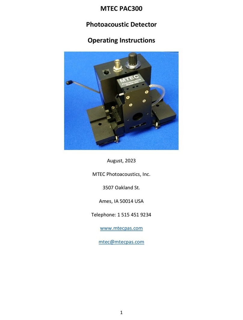
Fig. 3.1: Model 300 mounted in slide fixture with power supply
and purge flowmeter connected.
________________________________________________________________________
_
Artisan Technology Group - Quality Instrumentation ... Guaranteed | (888) 88-SOURCE | www.artisantg.com
4
Fig. 3.2: Sample cup with infrared sensing liquid crystals in place.
Fig. 3.3: View from above sample cup showing schematically three different
beam positions in the cup as imaged by the liquid crystal (actual
images will be larger relative to the cup diameter than shown here).
Position 1 indicates ideal alignment. Position 2 indicates that the
detector must be moved perpendicular to the beam in the opposite
direction to the direction of misalignment. Position 3 indicates that
the detector must be lowered. See the text for how to make
adjustments.
________________________________________________________________________
Artisan Technology Group - Quality Instrumentation ... Guaranteed | (888) 88-SOURCE | www.artisantg.com

5
3 Set Up Directions
3.1 Rear Lever Setting
The rear lever rotates through an angle of 900when samples are
changed. The end points of rotation can be adjusted to facilitate ease of
operation in a particular FTIR by mounting the lever in one of the three
sockets. These are shown in Fig. 3.5a.
3.2 Mounting and Aligning the Detector in the FTIR
The model 300 mounts in the sample slide fixture of the FTIR. This
fixture ideally should be located at the beam focus in the sample
compartment and the beam should pass through the center of the hole in the
fixture.
In practice, the slide fixture location may only be approximately
correct resulting in the beam focus in the model 300 sample cup being a little
off center. The focus centering is checked by placing one of the infrared
sensitive liquid crystals supplied with the model 300 in the sample cup. The
crystal should rest on the foam cylinder which itself should rest on a brass
spacer to elevate the crystal to near the rim of the sample cup (see Figure
3.2). Two crystals are supplied. Select by trial and error the one with the best
response given the ambient temperature of the laboratory.
In order to check alignment, place the detector in the slide fixture. If
the fixture has an adjustable lower stop for the slide, be sure that it is set so
that the holes in the slide fixture and in the mating model 300 slide plate are
concentric.
Block the infrared beam and insert the sample holder with the liquid
crystal into the model 300. Fully open the aperture of the FTIR. Elevate the
crystal by moving the rear lever to the CLOSED PURGE position. Remove
the beam block for several seconds and replace it. Immediately remove the
sample cup and examine the exposure pattern before it fades as the
temperature falls.
The types of patterns that may be observed are shown in Fig. 3.3.
Pattern 1 indicates ideal alignment. Pattern 2 shows side-to-side
misalignment. This can be corrected by moving the FTIR's sample fixture
perpendicular to the beam in the direction opposite to the misalignment
direction. Alternatively, side-to-side adjustment can be made by loosening the
screws as shown in Figure 3.4 and sliding side-to-side the model 300's slide
plate relative to its mounting yoke. If the FTIR has no provision for side-to-
side adjustment of its sample fixture, this alternative method must be used.
Artisan Technology Group - Quality Instrumentation ... Guaranteed | (888) 88-SOURCE | www.artisantg.com

6
Pattern 3 indicates that the model 300 needs to be lowered. Some FTIR
slide fixtures have provision for this adjustment while others do not. If there
is no adjustment provided on the FTIR, height adjustments are made by
placing small shims provided with the detector between the model 300 slide
mount and the yoke coupling plate. This location is indicated by the white
arrow in Figure 3.4.
If the infrared beam pattern appears in locations other than those
shown in Figure 3.3, the discussion above should also provide the needed
information for alignment. Adding shims lowers the detector and moves the
image in the direction of the infrared beam.
If the infrared beam pattern is large and weak, the FTIR's sample
fixture may not be in the focal plane of the sample compartment. This
condition requires that the fixture be translated forward or backward in the
beam direction. Trial and error must be used to find the best location.
Extra 5-40 thread support screws can be used as shown in Figure 3.5a
and Figure 3.5b to provide additional support for the detector if needed.
Contact MTEC if screws are not available locally.
Fig. 3.4: Wrench engaged in slide plate clamping set screw. The arrow
marks the place to insert shim plates for height adjustment.
________________________________________________________________________
Artisan Technology Group - Quality Instrumentation ... Guaranteed | (888) 88-SOURCE | www.artisantg.com

7
Fig. 3.5a: Extra support screws can be used at the rear of the detector. Note
the three slots that the lever can mate into thus positioning the
lever to rotate over a range suitable for different FTIR sample
compartments.
_______________________________________________________________________
Fig. 3.5b: Extra support screws installed at the front of the detector.
_______________________________________________________________________
Artisan Technology Group - Quality Instrumentation ... Guaranteed | (888) 88-SOURCE | www.artisantg.com

8
3.3 Purge Gas Connection
Assemble the flowmeter and connect the larger inlet hose barb of the
flowmeter to the pressure regulator of a tank of high purity helium gas (zero
grade) which is free of water vapor. Connect the plastic hose supplied
between the small outlet hose barb on the flowmeter and the stainless steel
tube on the top of the detector's slide plate. Consult section 4.5 before
attempting to purge the detector.
3.4 Electrical Connections
The desk top power supply pictured in Fig. 3.6 is designed to run on
either 115V 60Hz or 230V 50Hz line voltages. Select the proper voltage
setting by the red switch on the bottom of the unit. The IEC 320 input
connector will accept the proper cord set for the country of operation. The
white cable connects the power supply to the photoacoustic detector using
RJ11 telephone connectors. The green light will illuminate when the switch is
in the power on position.
The BNC connector carries the photoacoustic signal from the detector
to the FTIR signal input connector.
Special interfacing PAS preamplifiers, supplied by the respective FTIR
manufacturers, are required for: Nicolet 800 and all Magna models, Perkin-
Elmer System 2000, and all Bomem models (identify model). Consult the
manufacturers for details. No desktop power supply is provided if a cable is
supplied to directly power the Model 300 from the FTIR.
Fig. 3.6: Desk top power supply showing on /off light (1), switch (2), and
voltage selector switch (3).
______________________________________________________________________
Artisan Technology Group - Quality Instrumentation ... Guaranteed | (888) 88-SOURCE | www.artisantg.com

9
4 Operation
4.1 Preamplifier Gain Control
A twelve position switch controls the gain as follows:
step# 1 2 3 4 5 6 7 8 9 10 11 12
gain 2 5 10 20 50 100 200 500 1000 2000 5000 10,000
factor
The gain should be set high enough to give a reasonable interferogram
amplitude but not too high to either cause preamplifier clipping (<20V peak-
to-peak) or to overload the FTIR's A to D converter.
Higher gains are used for higher FTIR mirror velocities because the
signal amplitude decreases as modulation frequency increases. Higher gains
are also used when sample spectra are being acquired relative to carbon
black background spectra because totally absorbing carbon black generates
higher signal amplitudes than partially absorbing samples which usually also
have higher thermal mass.
4.2 Rear Lever Operation
The rear lever rotates over an angle of 900to elevate the sample holder
into the detector's sample chamber and to compress the o-ring to seal the
chamber. The lever also automatically controls the operation of the purge
valve during the 900rotation. A detent snap device indexes four rotational
locations over the 900rotation. These are the OPEN, OPEN PURGE,
CLOSED PURGE, and SEAL locations which are shown schematically on the
detector's sides for easy reference during operation.
In the OPEN location the sample holder may be withdrawn or inserted
for sample change.
In the OPEN PURGE location purge gas flows through the sample
chamber and out the bottom because the sample holder o-ring is not sealed.
In the CLOSED PURGE location purge gas flows past a hole leading to
the sample chamber but not through it. Consequently, purging is slower but
there is no flow over the sample which might blow powders out of the cup.
In the SEAL location the sample chamber is sealed and spectra may
be acquired. The purge gas still can flow but is sealed from the sample
chamber. Fig. 3.5a shows the lever in the seal location.
Artisan Technology Group - Quality Instrumentation ... Guaranteed | (888) 88-SOURCE | www.artisantg.com

10
Fig. 4.1: Sample holder with brass inserts and small and large cups.
_________________________________________________________________________
Fig. 4.2: Small cup in sample holder. Fig. 4.3. Large cup with polymer
pellets. A wrench is engaged
in one of the o-ring
compression adjusting screws.
________________________________________________________________________
Artisan Technology Group - Quality Instrumentation ... Guaranteed | (888) 88-SOURCE | www.artisantg.com

11
4.3 Sample Cup Loading
The MTEC Model 300 is supplied with five small and five large sample
cups and five brass spacer inserts. The cups and inserts fit into a brass
holder which is attached to the black sample holder handle as shown in Fig.
4.1. The slot in the brass part should be kept oriented perpendicular to the
handle length. The o-ring seals the detector when the lever is rotated fully to
the SEAL location and must be kept clean.
To avoid breaking the detector window, do not place anything
which extends higher than the rim of the brass cup holder in the
sample holder because when the rear lever is rotated to the SEAL
location, the rim is located just below the detector window. Anything
extending above the rim will be forced into the window and break it.
Samples, depending on size, are placed in the small sample cups or in
the large brass cup holder (in the latter case with or without a large sample
cup) as shown in Fig. 4.2 and Fig. 4.3. The brass spacer inserts (Fig. 4.1) are
used to eliminate excess volume in the sample cup. A higher signal level is
consequently obtained because the signal is inversely proportional to the gas
volume. The inserts and sample levels in cups should be chosen so that the
sample is approximately 1 mm or more below the brass cup holder rim. This
distance allows the photoacoustic signal to be generated in the gas without
thermal interference by the window above the sample. Course samples may
be placed in cups using tweezers. Fine powders may be loaded with the
funnel provided by first placing cups either directly in the brass sample cup
holder (Fig. 4.4) or in the slotted cup fixture (Fig. 4.5) and then placing the
funnel in position (the funnel fits on both the cup holders and cup fixture)
(Fig. 4.6). An alternative approach is to scoop powders from storage
containers with the sample cups held by tweezers and then use the slotted
cup fixture to align the tweezers in order to facilitate easy insertion of the cup
into the brass cup holder. Be careful not to spill samples onto the o-ring. Only
enough sample to cover the bottom of the sample cup is necessary.
Samples (both micro and macro) that evolve H20 vapor should be run
with a desiccant in the sample chamber to avoid vapor bands in spectra.
Magnesium perchlorate is a very effective desiccant and can often be used
safely. This chemical is, however, a strong oxidizing agent and may create a
hazard when used in close proximity with certain samples. It is the operator's
responsibility to consult and observe appropriate safety information.
Artisan Technology Group - Quality Instrumentation ... Guaranteed | (888) 88-SOURCE | www.artisantg.com

12
The desiccant is placed in a large sample cup. This cup is inserted into
the brass holder (Fig. 4.7), a slotted spacer insert is placed over the desiccant
cup, and the slots are aligned to permit gas circulation between the desiccant
and sample cups (Fig. 4.8). Finally, the sample is put in a second cup which is
inserted above the desiccant cup. Never leave desiccant in the sample cup
when the detector is not sealed because a corrosive liquid may form as
moisture is collected by the desiccant from the room air.
There are several effective approaches in addition to the desiccative
cup, which may be used alone or in combination to reduce vapor band
interference from a sample. These approaches include vacuum and/or oven
drying of samples prior to measurements, reduction of the amount of sample
placed in the cup, dry gas purging, and spectral subtraction. Interference
bands may also be present due to residual vapors in the detector from the
previous samples, degassing of internal components, or from the storage box.
These bands can be readily reduced to an acceptable level by purging. Note
that bands due to vapor absorption in the detector are always positive
pointing whereas vapor absorption in the spectrometer produces negative
pointing bands.
Fig. 4.4: Samples can be loaded Fig. 4.5: Fixture with sample cup
directly into the sample inserted.
holder cup.
_____________________________________________________________________
Artisan Technology Group - Quality Instrumentation ... Guaranteed | (888) 88-SOURCE | www.artisantg.com

13
Fig. 4.6: Sample loading funnel and cup fixture.
_______________________________________________________________________
Fig. 4.7: Cup with desiccant inserted. Fig. 4.8: Desiccant covered with
spacer plate with notches
properly aligned.
_____________________________________________________________
_
_________
Artisan Technology Group - Quality Instrumentation ... Guaranteed | (888) 88-SOURCE | www.artisantg.com

14
4.4 Sample Cup Insertion
The sample cup can be inserted from either side of the detector since
different sides of the detector are accessible with different FTIRs. Fig. 4.9
shows the sample holder ready to be slid into place for elevation into the
sample chamber and sealing. Fig. 4.10 shows it sealed.
Fig. 4.9: Sample cup ready for insertion and sealing.
_______________________________________________________________________
Artisan Technology Group - Quality Instrumentation ... Guaranteed | (888) 88-SOURCE | www.artisantg.com

15
Fig. 4.10: Sample cup inserted and sealed.
_____________________________________________________________________________________
4.5 Purging
Purging increases the signal level by approximately a factor of 2 to 3
and reduces moisture in the sample chamber. Care must be taken in purging
the detector, however, to avoid large pressure fluctuations that could damage
the microphone.
Use clean dry helium gas such as "zero grade". Only the primary
pressure regulator valve on the gas cylinder should be used to control the
flow rate. If the regulator has a second valve at the regulator output set this
valve to the full open position and leave it so set. Keep the detector lever in
the SEAL position whenever the gas is being turned on or off and when the
flow is being adjusted. These are the times when pressure surges are most
likely to occur and the SEAL position isolates the microphone.
Use a flow rate of 10-20 cc/s for most samples.
For fine powders reduce it to 5 cc/s or lower until the CLOSED
PURGE location is reached to avoid blowing the powder into the
detector.
Artisan Technology Group - Quality Instrumentation ... Guaranteed | (888) 88-SOURCE | www.artisantg.com

16
Ten seconds purge time in each of the purge locations is usually sufficient.
Longer times may be necessary if considerable moisture is present.
Leaving the detector sealed with desiccant under the sample cup for an
extended time is the best way to remove the last traces of moisture.
When the detector is initially purged with helium there will be a
gradual decrease in signal amplitude as helium exchanges with air in the
rear volume of the microphone that is connected to the sample chamber by a
fine capillary. This drift will be minimized if helium is kept sealed in the
detector at all times. The signal will also gradually decrease due to diffusion
of helium at the o-ring seals. Signal drift can be eliminated by purging with
dry nitrogen but the signal enhancement of helium is lost.
4.6 FTIR Operating Parameters
For general use, the following are usually
appropriate: 1. Minimum mirror velocity that
is stable 2. Maximum source aperture
3. Resolution of 8 cm-1
4. Scan number depending on signal-to-noise required
4.7 Test Procedure
1. Remove the red protective cap, place the carbon black reference (Fig.
4.11) in the detector and purge the detector, if desired.
CAUTION. Do not allow anything to contact the black
absorber surface of the carbon black reference. It is easily
punctured. Keep the red protective cap on the carbon black
reference when not in use. Do not leave the carbon black reference
in the detector when a background spectrum is not being acquired.
2. Adjust the detector gain for maximum signal without the
preamplifier clipping (clipping occurs at approximately 20 volts maximum
peak-to-peak) and without the FTIR input overloading. The presence of
clipping is usually evident by examining the FTIR center burst. Most FTIRs
will automatically indicate input overload.
3. If the PAC300 detector initially does not produce a signal, disconnect
and then reconnect the telephone connector on the white cable located next to
the detector's gain switch.
Artisan Technology Group - Quality Instrumentation ... Guaranteed | (888) 88-SOURCE | www.artisantg.com
Table of contents
Other MTEC Security Sensor manuals
Popular Security Sensor manuals by other brands

Bircher Reglomat
Bircher Reglomat Herkules 2 Translation of the original operation instruction

SICK
SICK Prime KTX-WB9114225UZZZZ manual

Keysight
Keysight 8478B Operating and service manual

Emerson
Emerson Rosemount 975 Series Reference manual

Draminski
Draminski PREGNANCY DETECTOR manual

Olympia
Olympia 5993 user manual