1
2
3
4
5
6
7
8
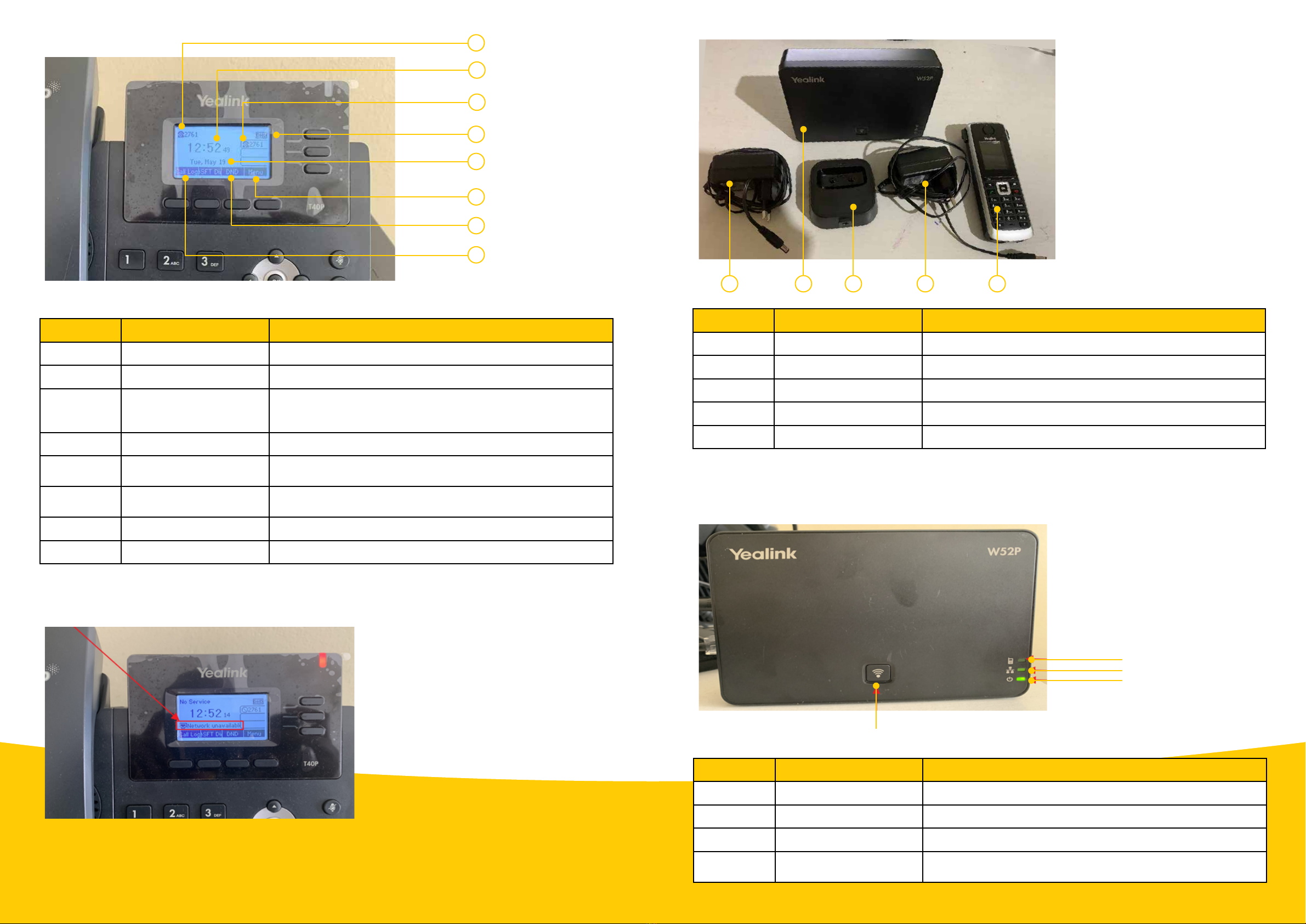
Item no. Label/Module Component description
1. Call log This shows the call history. (Please refer to the user manual.)
2. Date This displays the correct date.
3. Phone extension
This number indicates your four-digit extension number. These
four digits normally match the last four digits of your full
phone number.
4. Time This shows the correct time.
5. Extension number This shows the same number as the phone extension. (Please
refer to user manual.)
6. Do Not Disturb (DND) This indicates that DND is activated. As a result, the phone
won’t be able to receive calls. Ensure this icon is not showing.
7. DND This is used to activate and deactivate ‘Do Not Disturb’.
8. Menu Use this to configure the phone.
Note: If the phone is displaying ‘Network unavailable’, this might be because either the network (LAN) cable
is not connected, or the MTN fixed-LTE router is switched off.
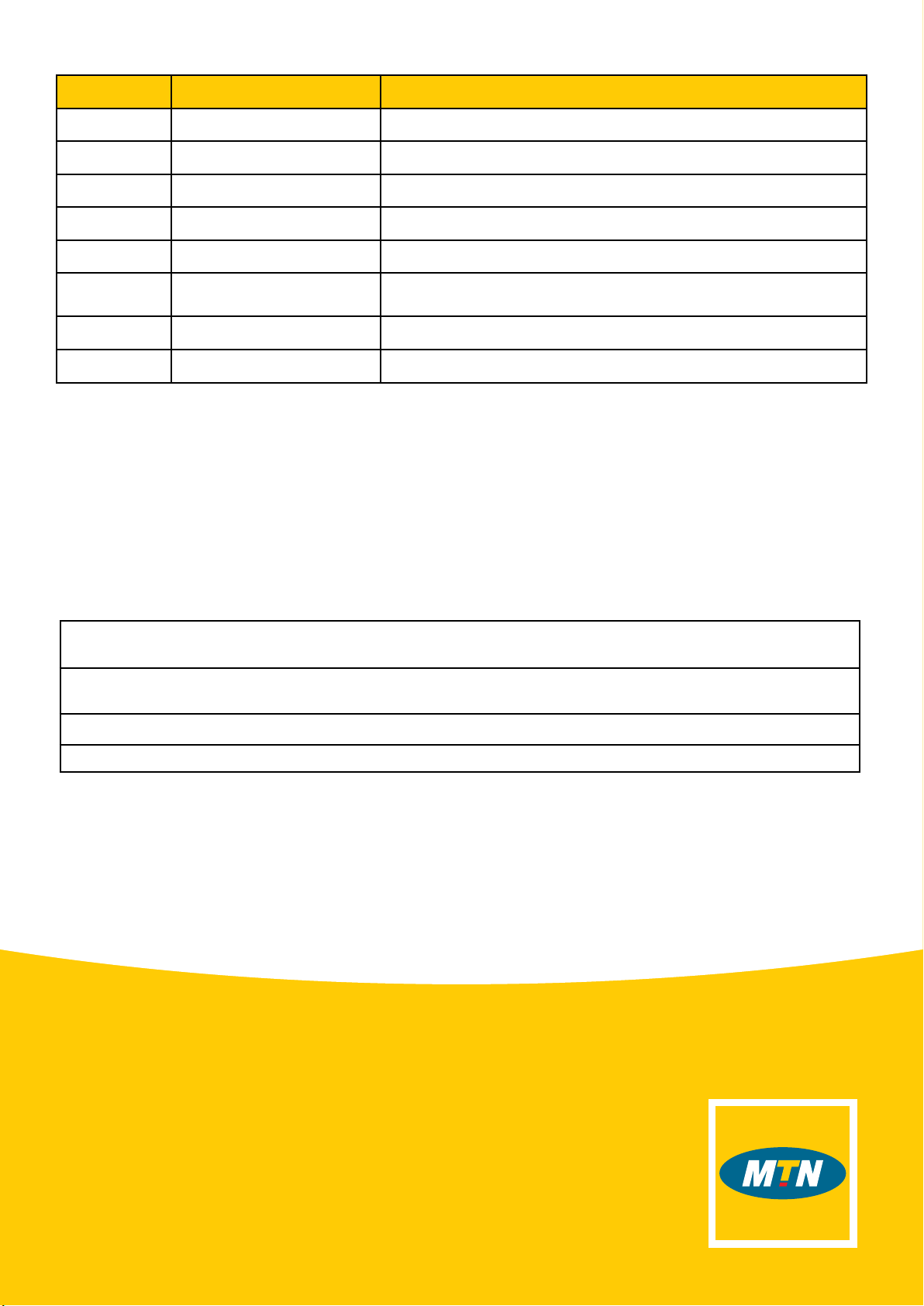
If you ordered the Yealink W52P, please follow the steps below:
1. Remove the phone from the box, with all the cables. You should have all the items shown on the next page.
1 2 3 4 5
Item no. Label/Module Component description
1. Power supply 1 This is used for powering the DECT base station.
2. DECT base station This provides a wireless connection to the DECT phone.
3. Docking station This is used to charge the DECT phone.
4. Power supply 2 This is used to power the docking station.
5. DECT phone This is used to make and receive calls.
Yealink T40P or T41S rear-view panel
Wi-Fi
Phone
Network
Power
Item Label/Module Component description
Phone DECT phone status light This indicates the status of DECT phone.
Network Network status light This indicates the network status.
Power Power indicator light This indicates the power status.
Wi-Fi Wi-Fi button This is used to page DECT phones or to display the DECT
phone IP address