MTS Systems Temposonics MH Series User manual

Document Part Number
551289 Revision C
Installation Manual
MH Series
Temposonics®MH/MS/MT
Absolute, Non-Contact Position Sensors
Temposonics®
All specifications are subject to change. Contact MTS for specifications and
engineering drawings that are critical to your application. Drawings contained in this
document are for reference only.
Please visit www.mtssensor.com for the actual support documentation- related to your
selected model.
Observe the propietary notice according to ISO 16016.
Unless explicitly permitted, distribution and reproduction of this
document as well as utilization and communication of its contents
are prohibited.
Violations are subject to indemnity. All rights for the case of patent,
utility model or industrial design registration reserved.

Contents
1. Safety and operation instructions....................................................................................................................................
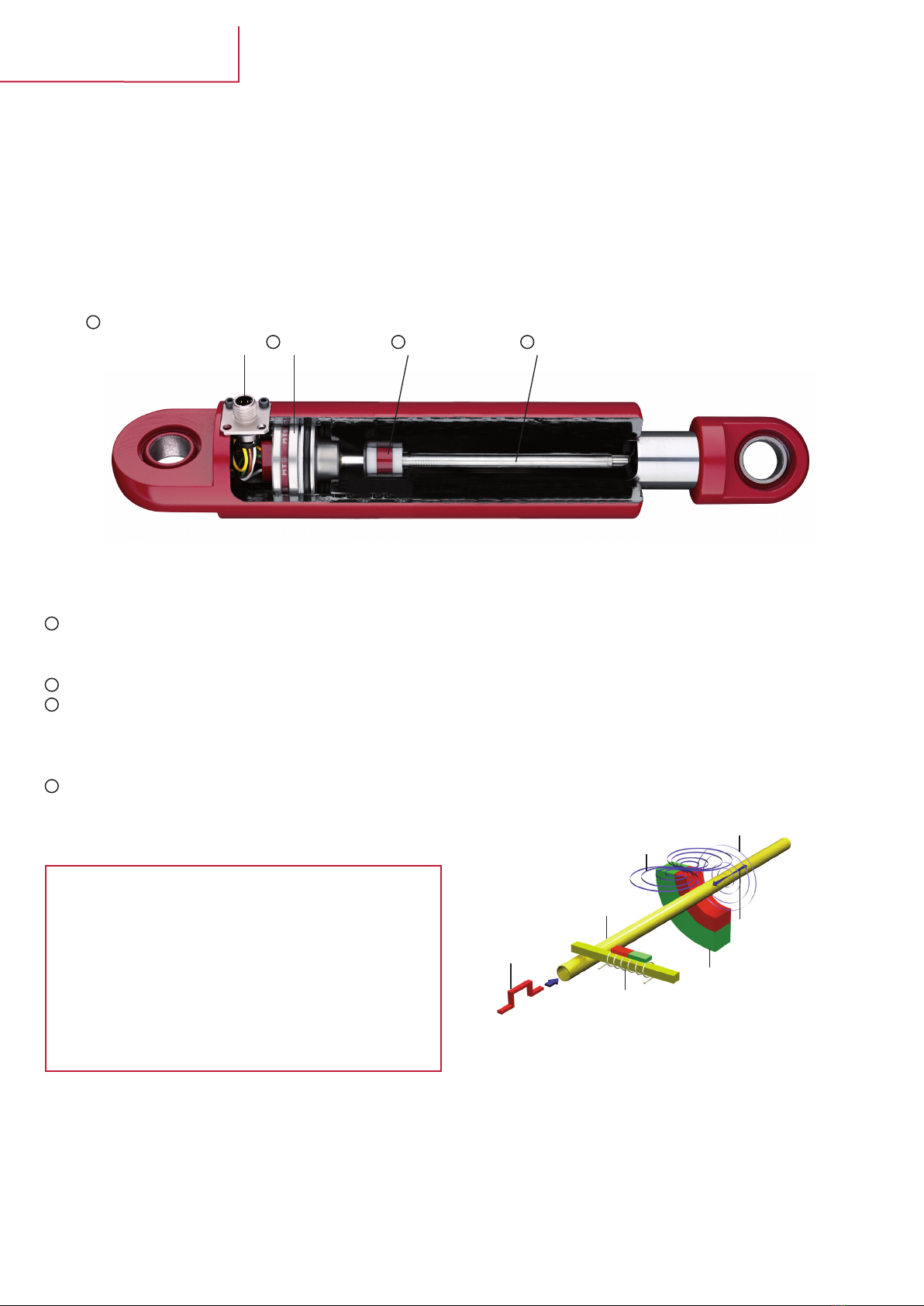
2. Product description and technology.................................................................................................................................
3. Space requirements - conditions, design
3.1 Dimensions, tolerances...................................................................................................................................................
3.2 Chamfered edge for insertion..........................................................................................................................................
3.3 Pistion rod bore and depth..............................................................................................................................................
3.4 CAD-data, download........................................................................................................................................................
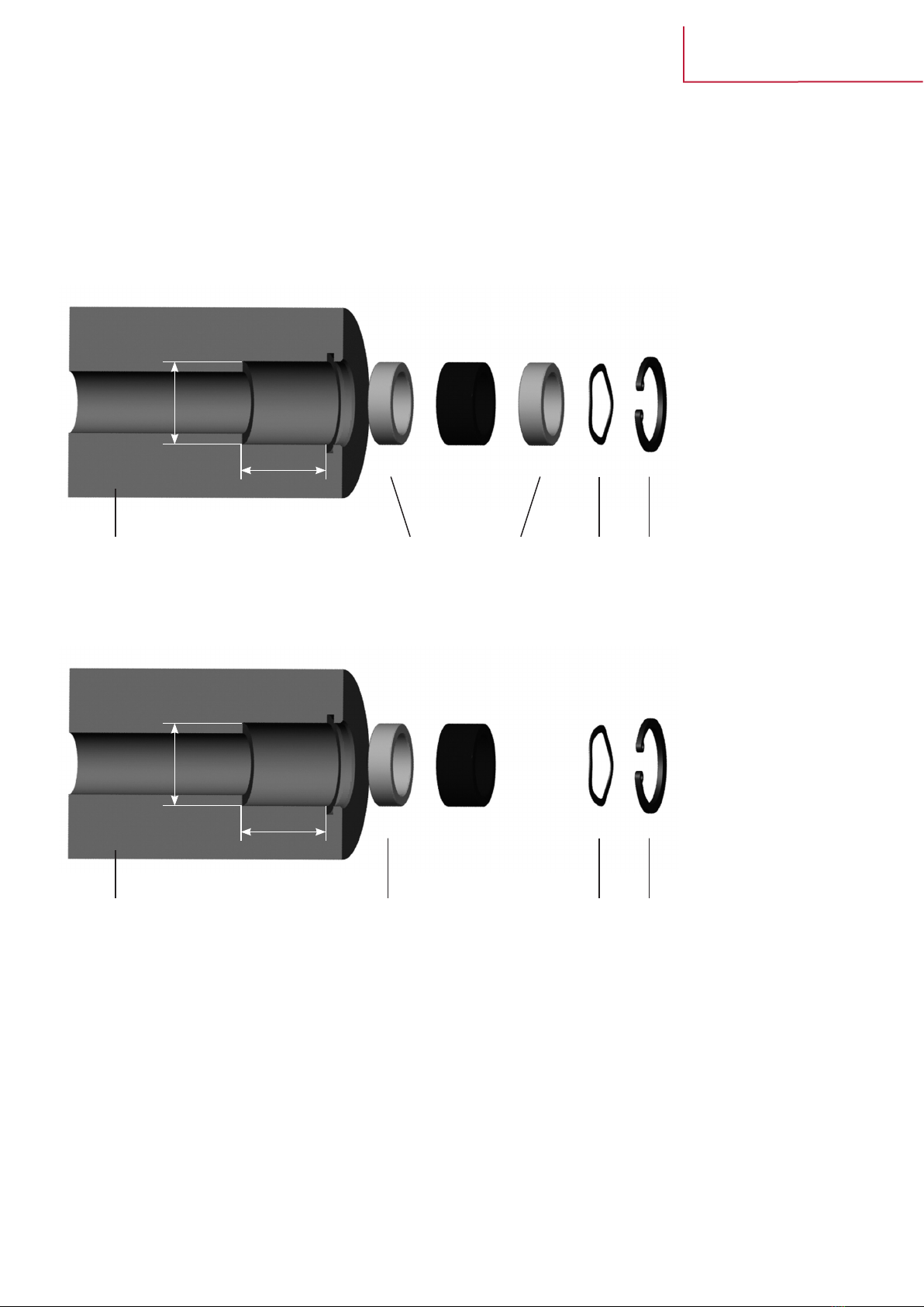
3.5 Installing the magnet.......................................................................................................................................................
3.5.1 Magnet with 2 distant washers...................................................................................................................
3.5.2 Magnet with 1 distant washer.....................................................................................................................
3.5.3 Installing the magnet..................................................................................................................................
3.6 Safety screw to DIN 913..................................................................................................................................................
3.7 Supporting long sensor pipes, sagging...........................................................................................................................
4. Mounting
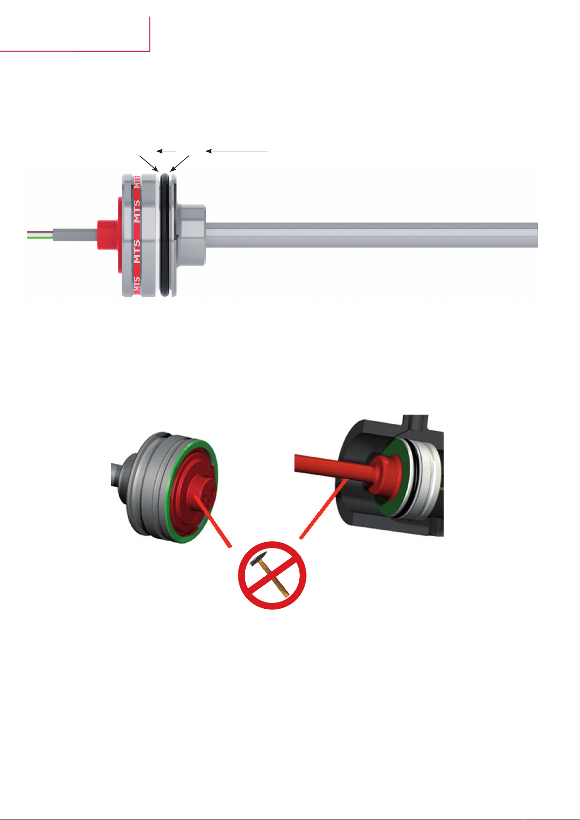
4.1 Positionining of O- and backup rings..................................................................................................................................
4.2 Load-bearings geometries of sensor housing.................................................................................................................
4.3 Mounting in the cylinder..................................................................................................................................................
4.4 Handling connection cables during mounting..................................................................................................................
4.5 Mounting sensors using a Temposonics®M12 connector system..................................................................................
4.6 Mounting in the cylinder..................................................................................................................................................
4.7 Mounting sensors with cable or single conductor connection.........................................................................................
4.7.1 Mounting sensors with cable connection and cable gland...........................................................................
4.7.2 Mounting sensors with single conductor and third-party connector...........................................................
5. Cylinder handling after sensor installation
5.1 Washing and drying cylinders with installed sensors......................................................................................................
5.1.1 Sensors with Temposonics®M12 connector system..................................................................................
5.1.2 Sensors with connecting cable...................................................................................................................
5.1.3 Sensors with third-party connectors..........................................................................................................
5.2 Painting of cylinders............................................................................................................................................................
5.2.1 Electrostatic painting..................................................................................................................................
5.2.2 Cylinders with integrated sensors and Temposonics®M12 connector system...........................................
5.2.3 Cylinders with integrated sensors and connecting cables or third-party connectors..................................
6. Transport, intermediate storage
6.1 Mounting/dismounting cylinders on mobile hydraulics machines...................................................................................
6.2 Electrical and electrostatic effects...................................................................................................................................
6.3 Electrostatic effects.........................................................................................................................................................
7. Drawings
7.1 Dimensions of Temposonics®MH sensor
- with M12 connector system..............................................................................................................................
- with single wires...............................................................................................................................................
- with cable..........................................................................................................................................................
- with cable (till 03.2011).....................................................................................................................................
7.2 Dimensions of Temposonics®MS sensor
- with M12 connector system..............................................................................................................................
- with single wires...............................................................................................................................................
- with cable..........................................................................................................................................................
7.3 Dimensions of Temposonics®MT sensor
- with M12 connector system..............................................................................................................................
- with single wires...............................................................................................................................................
- with cable..........................................................................................................................................................
7.4 Dimensions of sensor magnets (position transducer) ....................................................................................................
7.5 Mounting sensors using Temposonics®M12 connector system (flange)........................................................................
7.6 Dimensions of turned parts made of M12 round material................................................................................................
3
4
5
6
6
6
7
7
7
8
8
9
10
10
11
13
14
14
16
16
16
17
17
17
17
18
18
19
19
20
20
21
22
23
24
25
26
27
28
29
30
31
32
33
34

I3I
Temposonics®MH Series
Installation Manual
1. Safety operating instructions
Before starting the sensors operation, please, read this documentation carefully and follow the safety instructions.
This technical documentation provides information on the mechanical installation of Temposonics®sensors by qualified personnel* or trained
service technicians who are familiar with sensor projecting and handling.
Intended use
Temposonics®sensors are built according to actual electrical engineering standards. They are state-of-the-art and meet the EMC-
requirements for interference emission and immunity for vehicles and mobile machines. Nevertheless, using the sensors can result
in hazards for the user or third parties, or cause damage of the sensor and other equipment.
The sensors are intended for measuring tasks in the field of mobile hydraulics. They are considered as accessories and must be connected to suit-
able evaluation electronics, e.g. a PLC, IPC, indicator or another type of electronic control unit.
As a prerequisite to ensure perfect and safe sensor operation, correct transport, storage, mounting, commissioning and careful operation are man-
datory. The sensors may be used only in safe condition. To maintain this condition and ensure safe operation, installation, connection and service
work may be performed only by qualified and authorized personnel.
Information related to danger
Information related to danger is intended for your personal safety and for the safety of the described product or connected equipment against dam-
age.
Installation and operation
If failure or functional disorder of the sensors cause danger for persons or imply a hazard of damage to operating facilities, additional safety mea-
sures such as plausibility checks, limit switches, EMERGENCY OFF systems, protective devices, etc. must be provided to prevent it. In the event of
trouble, shut down the sensor and protect it against unauthorized operation.
To maintain the sensor operability, it is indispensable to observe the following information:
- Protect the sensor against mechanical damage during installation and operation.
- Don‘t open or dismantle the sensor.
- Connect the sensor carefully and make sure that the polarity of connections, the operating voltage as well as the shape and duration of control
pulses are correct.
- Use only approved power supply units.
- Observing the permissible sensor limit values for operating voltage and environmental conditions etc. as specified in the product documentation is
indispensable.
- Check and document the function of the position sensor regularly.
- Before activating the equipment, make sure that nobody‘s safety is impaired by starting machines.
Repairs
Repairs on the sensor may only be performed by MTS or a body that has been explicitly authorized by MTS.
Warranty
The MTS warranty period for the sensors and the accessories included in the scope of supplies in the event of material defects and faults occurred
although the intended use has been observed is 12 months from the reception of products.
The MTS liability is limited to repair or replacement for every defective component of the unit. Warranty for defects due to incorrect use or exces-
sive strain of the product as well as for wear parts is excluded. MTS rejects any liability for consequences or side effects in case of violation of the
warranty provisions**, independent of whether warranty has been assured or expected. This is also applicable in the event of an error or negligence
committed by the company. MTS explicitly refrains from making any additional warranty promises. Representatives, agents, dealers and members
of the personnel are not authorized to increase or change the warranty conditions.
* Qualified personnel means persons who are
- familiar with the projection of safety concepts for automation equipment.
- competent in the field of EMC.
- have been trained adequately for commissioning and service work
- familiarized with the operation of the equipment and know the information required for perfect operation given in the product documentation.
** see MTS sales and supply conditions, e.g. available for download from www.mtssensor.de

I4I
Temposonics®MH Series
Installation Manual
2. Product description and technology
Temposonics®sensors can be used in versatile mobile machines without any restriction and replace contact-based linear sensors like poten-
tiometers. Highly dynamic systems are controlled safely by means of Temposonics®sensors, thus enhancing the productivity, availability and
quality of the working process of the machine. Insensitive to vibration, shocks, dust and weathering influence and electro-magnetic disturbanc-
es. Temposonics®MH Series sensors are successfully used in front axle and articulated frame steering cylinders, hydraulic jacks and in steering
systems for hydraulic units on agricultural and construction machinery.
Magnetostriction
Temposonics®linear sensors are based on the magnetostrictive tech-
nology. By measuring the actual position with a non-contact position
magnet the sensor operates 100% wear-free. The absolute operating
principle enables reliable readings without any reference point or
recalibration. A mechanical strain pulse is triggered by the travelling
position magnet. The runtime of this ultrasonic wave is measured
precisely and compiled into standard electronic output signals.
Simple Mechanics
The extremely robust sensor consists of the following main parts:
The innovative connector system which is easy to install in a few
seconds, any soldering or crimping needless, dust-and waterproof
up to IP69K.
The flange housing with built-in electronics and signal converter.
The position magnet as only moving part, which is assembled
into the piston bottom. This permanent magnet travels wear-free
and contactless along the pressure pipe and measures the actual
position.
The pressure pipe placed within the drilled piston rod contains the
protected magnetostrictive sensing element. Measuring principle
Temposonics®
Connector system (IP69K) Flange housing Position magnet Pressure pipe
1
234
1
2
3
4
- Due to small dimensions MH sensors require only little space
- Suitable for operating pressures up to 350 bar
- Unaffected by surrounding media such as ageing or foaming oil
- Insensitive to shock and vibration
- Designed for all current supply voltages (12/24 VDC)
- Temposonics®sensors offer all common used output signals:
Analog: VDC /mA•
PWM•
Bus protocols: CANopen, SAE J1939•
Magnetic field
strain pulse
Magnetic field
position magnet
Mechanichal
strain pulse
Moveable
position magnet
Strain pulse
detector
magnetostrictive
sensing element
(waveguide)
Current
interrogation
pulse

I5I
Temposonics®MH Series
Installation Manual
3. Space requirements - conditions, design
3.1 Dimensions, tolerances
Type B
Ø cylinder
D
Ø min.
H
Depth
d
Ø min.
h
Depth
MS 32 mm 28H7 screwed
28G7 welded 26.8 mm + 0.2 23.5 mm < 25 mm
MH 52 mm 48H8 screwed
48G7 welded 21.2 mm + 0.2 > 32.5 mm
< 40 mm
> 18 mm (cable)
> 15 mm (core))
MT 52 mm 48H8 screwed
48G7 welded 39.9 mm + 0.2 37 mm > 22 mm
Installation, housing Installation space
Dd
H h
B
Surface Ra < 0,8 mm

I6I
Temposonics®MH Series
Installation Manual
3.2 Chamfered edge for insertion
For correct and easy sensor mounting in the cylinder, a chamfered edge as shown in the drawing is required. To avoid damaging the O-ring during
installation, the radius at the transition from borehole to chamfered edge must be R0.6 - R1. Without this radius, there would be a sharp edge,
which could damage the O-ring.
3.3 Piston rod bore and depth
Declarations in agreement with actual data sheet and selected model no.
The borehole depth is composed of measuring range (S), dampening (D)
and a clearance of 3 mm (depth = S + D + 3 mm).
ØPressure pipe ØPiston rod
MS 7 mm 10 mm
MH 10 mm (7 mm) 13.5 mm (10 mm)
MT 10 mm 13.5 mm
3.4 CAD data, download
CAD models of all Temposonics®MH, MS and MT sensor models are available for download in many commonly used data formats on the MTS
website (www.mtssensor.com). Go to our website, select Europe -> Support -> Login. Send a password request and you will be granted access to the
menu for engineering drawings, where you will find the 3-D model configurator for CAD model download.
All dimensions in mm
MH MS MT
N= Null zone 30 mm 22 mm 30 mm
S= Stroke range
acc. to actual data sheet and selected model no.
D= Damping
Please pay attention:
•Thepositionmagnetshallnottouchthepressurepipe.
•Donotexceedoperatingpressure.
BDetail B
NS D > 3 mm

I7I
Temposonics®MH Series
Installation Manual
3.5 Installing the magnet
Use only distance washers of non-magnetic materials such as polyamide or aluminum. We recommend securing the magnet by means of a spring
washer and a retainer. If these parts are of non-magnetic stainless steel, the second distance washer is not required (see section 3.5.2).
3.5.1 Magnet with 2 distant washers
3.5.2 Magnet with 1 distant washer
S M S W C
Ø
d
magnetic (steel) POM, PU, Aluminium magnetic (steel)
S M S W C
Ø
d
magnetic (steel) POM, PU, Aluminium non-magnetic (stainless steel)

I8I
Temposonics®MH Series
Installation Manual
3.5.3 Installing the magnet
M Magnet
Description 401 032 400 533 201 542-2
ØBorehole diameter 17.5 +0.1 25.5 +0.1 33 +0.1
dDepth
1 Distant washer
2 Distant washers
13.0 +0.1
18.0 +0.1
SDistant washer
OD x 5 x 13,3 17.4 +0.1 25.4 +0.1 33.0 +0.1
MMagnet 17.4 x 8 x 13.5 25.4 x 8 x 13.5 33.0 x 8 x 13.5
WCorrugated washer OD: 16.5 - 17.4
ID: 13.5 - 14
OD: 24.5 - 25.4
ID: 13.5 - 14
4 x M4
1 Nm
CCirclip DIN 472 - 18 x 1 25 x 1 4 x M4
1 Nm
3.6 Safety screw to DIN 913
For MH and MT sensors, an M5x10 set screw to DIN 913 with flat point should be used. This safety screw is only required for blocking the sensor
housing in axial direction and needs to butt only against the groove, i.e. the screw may be tightened only with a max. torque of 0.5 Nm to prevent
damaging the sensor. The set screw should be inserted with a resolvable safety adhesive, e.g. Loctite blue.
All dimensions in mm
4.5
4
45°
4.5
8.5
1
Detail housing
Detail safety screw

I9I
Temposonics®MH Series
Installation Manual
3.7 Supporting long sensor pipes, sagging
From a sensor measuring length of 1500 mm, the weight of the sensor can cause sagging of the sensor rod in horizontal cylinder mounting posi-
tion. Sagging does not affect the sensor function, since the sensor pipe is damped by the surrounding oil and lubricated when contacting the piston
rod. Generally, however, the following measures can be taken with long sensor rods:
Install a slide bushing at the end of the sensor rod (right figure). The pressure pipe is provided with a threaded port at the end. For assembling and
fixing the pressure pipe use corresponding srews. The maximum tightening torque for screws is 2.5 Nm (the screw property class must be taken
into account).
Spacing washers should be of non-magnetic, sliding material (e.g. polyamide) and dimensioned so that the inside diameter is smaller than the one
of the position magnet. A smaller inside diameter prevents the sensor rod from touching the magnet, thus protecting it against wear (see figures).
Another possible way to prevent the sensor rod from sagging is using slide bushings of non-magnetic material in the piston rod (see figure).
9.5
6
Ø 10
M4
8.5
Slide bushing
Magnet
Spacing washers
Slide bushingMagnet
Spacing washers

I10I
Temposonics®MH Series
Installation Manual
4. Mounting
4.1 Positioning of O- and backup rings
O-ring and backup ring have been fitted at the factory as shown in the figure.
4.2 Load-bearing geometries of sensor housings
Only the surfaces marked in green may be loaded when mounting the sensor in the cylinder.
Surfaces marked in red must not be subjected to any forces or even hammer strokes.
Backup ring O-ring Oil pressure

I11I
Temposonics®MH Series
Installation Manual
4.3 Mounting in the cylinder
Lubricate O-ring and backup ring before mounting in the cylinder.
Push the sensor into the seat carefully. Make sure that conductors or
cables are not under strain.
Use an individually prepared bush (e.g. polyamide) to press the sensor
into the seat.

I12I
Temposonics®MH Series
Installation Manual
If necessary, use only a rubber mallet to hammer the sensor in
position carefully.
Never use a steel hammer. Don‘t subject the sensor and the tools to
hard strokes during installation.

I13I
Temposonics®MH Series
Installation Manual
4.4. Handling connecting cables during mounting
When mounting, take the connecting cables through the cylinder wall carefully. Avoid tensile stress acting on the connecting cable.
Never expose the connecting cable to tensile stress and protect it against sharp edges, which might damage the insulation of the connecting
cables!

I14I
Temposonics®MH Series
Installation Manual
4.5 Mounting sensors using a Temposonics®M12 connector system
The Temposonics®M12 connector system is connected to the sensor and ready for installation. After installation in the cylinder and inserting the
mating plug, it meets the high requirements of protection class IP68 and IP69K. Soldering, screwing or crimping is not necessary. The risk of con-
tact faults, corrosion of contacts and faulty connection is also omitted. When you select suitable mating plugs, make sure that these plugs are also
protected to IP68 or IP69K, because this protection class can only be ensured if suitable mating plugs are used.
Dimensions (see Annex)
4.6 Mounting in the cylinder
Introduce the contact carrier (black plastic part) through the cylinder wall carefully. Make sure to keep the conductors away from sharp or pointed
edges.
Insert the contact carrier into the flange plate and click it in position. Note the nose of the contact carrier and one of the two apertures of the
flange connector, since the contact carrier can be inserted also at an angle of 45°.
Contact support for snapping
into 2 staggered positions, at
an angle of 45° to the flange
plate
Flange plate in 4 positions
staggered by 90°, for screw
mounting
12
1
2

I15I
Temposonics®MH Series
Installation Manual
Apply lubricant for O-rings and press the flange plate into the borehole in the cylinder wall. Fasten the flange plate using screws or rivets according
to the list given below. The dimensions of screws for mounting the flange plate should be selected so that they don‘t collide with the lock nuts
of the connected mating plugs.
Recommended cylinder head screws:
Recommended M4 cylinder head screws with pan head,
max. diameter 7mm:
• HexagonsocketheadcapscrewtoDIN912
•Hexalobularsocketcylinder head screwtoISO14580
• SlottedscrewtoDIN84
• Comparablecross-headscrew
• Comparablethread-formingscrews
Screws should be inserted using resolvable safety adhesive.
Alternatively, mounting can be done using a round head rivet to
DIN660.
Non-recommended screws:
• Hexagonheadscrews
• Countersunkheadscrews
• Self-tappingscrews
Hexagon socket head cap srew
Torx screw:
Slotted screw

I16I
Temposonics®MH Series
Installation Manual
4.7 Mounting sensors with cable or single conductor connection
Temposonics®sensors are protected according to IP67 (MH) or IP65 (MS, MT). To further minimize the ingress of water into the sensor housing,
important aspects should be taken into account when sealing the sensor as well as the cable or conductor connection.
4.7.1 Mounting sensors with cable connection and cable gland
When using third-party connectors with Temposonics®sensor cables, the following conditions must be met:
•TheconnectorprotectiontypeshouldbeatleastIP68.
•Theconnectorsshouldenclosealsothecablesheathing,inordertopreventexposedconductorsandtoprovidestrainrelief.Otherwise
the conductors are not sufficiently protected against external effects.
•Unlessthecablesheathingisenclosedbytheconnector,waterrunningalongthecablecanenterthecableatthepointwherethe
sheathing has been stripped.
•Ifthecablesheathingisnotenclosedbytheconnector,gasketmaterialshouldbeappliedtothepointatwhichthesheathinghasbeen-
stripped, in order to preclude the ingress of water.
•Makesurethatthepolarityiscorrect.
•Forconnectorswithscrewterminals,cableendsleevesshouldbeusedtoavoidshortcircuiting.
•Ifconnectorsareequippedwithsoldercontacts,makesurethatthecontactsaresolderedcorrectly.
•Crimpcontactsonconnectorsshouldbegas-tightandpressedonlyusingsuitabletools,becausethisisthepre-requisiteforprecluding
contact defects due to corrosion.
•Whenmountingconnectors,makesureprotectionagainstESDisprovided,i.e.workplacesandpersonnelmustbeprotectedagainst
electrostatic charging.
•Cableglandsshouldbeprotectedagainstdamagebysurroundingsteelproles(e.g.U-steel)
4.7.2 Mounting sensors with single conductor and third-party connector
When mounting third-party connectors on sensors with single conductors, the following information should be taken into account:
•TheconnectorprotectiontypeshouldbeatleastIP68.MakesureO-ringsarettedcorrectly.
•Theconnectorhousingshouldbecompletelyofmetal.Plasticconnectorscanbedamagedeasily,thustightnessisnotensured.
•Makesurethatthepolarityiscorrect.
•Forconnectorswithscrewterminals,cableendsleevesshouldbeused,inordertopreventshortcircuitingandcontactcorrosion.
•Endsleevesshouldbepressedontotheconductorsinawaythatallstrandsareclampedintothesleeve.Protrudingstrandscancause
short circuiting!
•Ifconnectorsareprovidedwithsoldercontacts,ensurethatthecontactsaresolderedcorrectlyandthatnostrandsstandproud.
•Crimpcontactsshouldbegas-tightandpressedonlyusingspecialcrimptools.Thisisthepre-requisitetoprecludecorrosionofcon-
tacts.
•Mostcommerciallyavailableconnectorsarenotornotsufcientlyprotectedagainsttheingressofwaterrunningalongthecable.
For this reason, suitable caps should be fitted to close them after mounting.
•Whenmountingconnectors,makesureprotectionagainstESDisprovided,i.e.workplacesandpersonnelmustbeprotectedagainst
electrostatic charging.
Sensors with cable connection should be mounted using an (ideally
metal) IP68 cable entry gland for sealing and strain relief. Make sure
that strain relief is provided in the further cable run.
Cable gland

I17I
Temposonics®MH Series
Installation Manual
5. Cylinder handling after sensor installation
5.1 Washing and drying cylinders with installed sensors
Frequently, hydraulic cylinders are washed or degreased before painting. For this purpose, various chemical and/or thermal methods are used,
whereby cleaning agents are sprayed onto the components under high pressure up to 50 bar. During this procedure, the following measures relat-
ing to polyurethane (PUR) connecting cables and plug-in connections must be taken.
5.1.1 Sensors with Temposonics®M12 connector system
•Whenwashingatlowpressuresuptoapprox.5bar,theplasticcapsuppliedwithsensorandconnectorsystemissufcientto
protect the M12 connector system (MTS material number GZ0605).
•Whenwashingathigherpressures,anM12x1metalprotectivedeviceshouldbeusedtoprotecttheconnectorsystemagainst
the effect of chemicals.
•TheactualMTSconnectorsystemwon‘tbedamagedduetoitshighprotectionclass,however,matingplugswhicharecon-
nected subsequently might corrode due to the effect of chemicals.
•Iftemperatureshigherthan105°Careusedfordryingafterwashing,theconnectorsystemsshouldnotbeexposedtothis
temperature during more than about 5 minutes.
5.1.2 Sensors with connecting cable
•Protecttheconnectingcablesusingsuitableenclosures(e.g.bags)againsttheeffectofmoisture,highpressuresandtempera-
tures.
•Normally,cableentryglandsmeettherequirementsofIP67,however,theyarenotpressure-tight.Forthisreason,theymust
be protected against moisture as well, in order to prevent moisture from accumulating in the connecting compartment of the
cylinder.
•MTSconnectingcablesaremadeofPURandrelativelyresistantagainstalargevarietyofchemicalsandoils.However,excep-
tions are e.g. carbon tetrachloride, trichloroethylene, perchloroethylene, which can be ingredients of fat solvents and cleaning
agents.
•Therefore,makesurethatcablesareprotectedadequately,ifcleaningagentsthatcanattackPURareused.
•Iftemperatureshigherthan105°Careusedfordryingafterwashing,theconnectingcablesshouldn‘tbeexposedtothistem-
perature during more than 5 minutes.
5.1.3 Sensors provided with third-party connectors
•Ifthird-partyconnectorsareused,asealedscrewcapmustbettedwhenwashing,sincethird-partyconnectorsnormallyhave
only protection class IP67.
•Moreover,checkifthehousingofthethird-partyconnectorissufcientlytighttoresisthighpressureswhenwashing.Ifneces-
sary, measures for protection of the housing should be taken.
•Theseconnectorsmustbeprotectedagainsttheingressofmoistureaswelltopreventmoisturefromaccumulatinginthecon-
necting compartment of the cylinder.
•Iftemperatureshigherthan105˚Careusedfordryingafterwashing,third-partyconnectorsshouldn‘tbeexposedtothistem-
perature during more than 5 minutes either.
IP69 K
IP67
IP67

I18I
Temposonics®MH Series
Installation Manual
5.2 Painting cylinders
5.2.1 Electrostatic painting
Sometimes, various dry and wet methods implying the application of paint to the component surface using electrostatic charge to paint cylinders
are used. These methods employ very high voltages up to 100 kV, which can damage the electronics of Temposonics®position measuring systems.
To prevent this damage, it is mandatory to take the following measures during electrostatic painting.
•Attachthecylindertothepaintingframebythefootsideofthecylinderratherthanbythepistonrod.Thereasonisthattheintegratedsealingand
slide rings can cause electric isolation between the piston rod and the cylinder/sensor housing, i.e. low-impedance connection between the paint-
ing equipment ground and the sensor housing is not ensured.
•Cleanthesuspensionpointsatthepaintingsystemandallconnectionsusedforshort-circuitingconductorsandconnectiontothepaintingsystem
ground regularly and remove paint as well as other residues, in order to ensure low-impedance connection.

I19I
Temposonics®MH Series
Installation Manual
5.2.2 Cylinders with integrated sensors and Temposonics®M12 connector system
When using dry or powder painting methods for cylinders, powder is applied to the component surface by means of static charge. These methods
employ very high voltages that can damage the electronics of Temposonics®position measuring systems integrated in the cylinders. This can be
prevented using the following metal protective caps.
The metal protective cap safeguards the contact pins and thus the electronics of the sensor against electrostatic effects (high voltage). It is impor-
tant to note that:
•Thematerialoftheprotectivecapmustbepermanentlyelectricallyconducting.
•Thecapmustnotbeofaluminum(aluminumissubjecttooxidationandcancauseelectricisolation).
•ThemetalprotectivecapmusthaveanM12x1thread.
•Thecapmustbescreweduptotheconnectorangeplate.
•Makesurethatnopaintparticlescontaminatethethreadorthecontactpins.
•Thethreadoftheprotectivecapmustbecleanandfreefrompaintparticlesandothersubstancesatalltimes.
•Themetalprotectivecapmustbetightenedonlysothatitishand-tight(max5Nm).
•Paintparticlesonthecapoutsideareuncritical.
Drawing examples for the protective cap are given in the attachment.
5.2.3 Cylinders with integrated sensors and connecting cables or third-party connectors
Electrostatic painting cannot be used for sensors with connecting cables, since the cable cannot be protected safely against the high
process voltage. Safe electrostatic painting is ensured only in conjunction with the MTS M12 connector system and the brass caps shown
in chapter 7.6.
Suspended from the cylinder foot - no potential formation between
sensor housing and sensor connections
Suspended from the piston rod – high potential (high voltage) between
sensor housing and connecting cable possible

I20I
Temposonics®MH Series
Installation Manual
6. Transport, intermediate storage
When transporting the cylinders, make sure that the cables and connectors are not under tensile stress. When handling/storing carelessly, connec-
tors and cables can be squeezed easily between stacked cylinders.
Moreover, it is necessary to encapsulate the connections or exposed cable ends using an antistatic bag. For this, the original bags (MTS material
number V0108) can be re-used. Furthermore, it is important to re-fit the white dust protective caps (MTS material number GZ0605) on the MTS
IP69K connector system after installation of the connector. The cylinders storage conditions should be as dry as possible.
6.1 Mounting/dismounting cylinders on mobile hydraulics machines
As during transport, connectors, cables and cable ends should be protected sufficiently during mounting and dismounting. Cables and conductors
must be neither subjected to load or tensile stress, nor bended. When connecting cables are installed, make sure that the insulation is not damaged
by sharp edges.
6.2 Electrical and electrostatic effects
Insulation tests
Part of the tests performed on mobile machines can be insulation tests. These tests are intended to determine the dielectric strength of
the cables against the housing (insulation resistance) using high voltages. During these tests, all sensor cables must be disconnected,
otherwise stray voltage over the sensor protective circuitry against ground can damage these components and cause sensor failure.
Welding
After installation of the cylinders in machines, welding work on adjacent components may be necessary. If the grounding tong is applied too closely
to or even directly on the cylinder, welding currents can be transmitted to the sensor via the cylinder, which can cause melting of the sensor pipe or
damage of internal sensor components.
Cylinders mostly consist of two assemblies: the lower part with the cylinder pipe (Figure, shown in dark gray) and the piston with the piston rod
(light gray).
These components are isolated electrically from each other by gaskets, bearings and slide rails, i.e. normally, no current flow is possible.
With long sensors, however, the sensor pipe can sag due to its own weight and touch the wall of the piston rod borehole. In this case, there is an
electric connection. The entire welding current flows through the sensor pipe and the sensor head and damages the electronics.
Therefore, the instructions given below must be followed:
•Cutordisconnectallsensorconnectionsduringwelding.
•Neverfastenthegroundingpointatthepistonrodoratthecylinderpipe.
•Neverweldonapartofthecylinder,ifasensorhasbeeninstalled.
•Neverperformweldingworknearacylinder,ifasensorhasbeeninstalled.
•Duetoinsulatingbearings,plasticslidebearingsorgreaseinthecontactspoints,electricpotentialscanbuild
up at every bearing point of machines. Accordingly, similar effects as on hydraulic cylinders.
As a rule:
Don‘t perform welding work on the cylinder!
Other manuals for Temposonics MH Series
1
This manual suits for next models
2
Table of contents
Other MTS Systems Accessories manuals

MTS Systems
MTS Systems R Series V User manual

MTS Systems
MTS Systems Temposonics MH Series Reference guide

MTS Systems
MTS Systems Level Plus M-Series MR Quick guide

MTS Systems
MTS Systems Temposonics R V Series User manual

MTS Systems
MTS Systems Temposonics R-Series User manual

MTS Systems
MTS Systems Temposonics R V SSI Series User manual

MTS Systems
MTS Systems Temposonics R V POWERLINK Series User manual

MTS Systems
MTS Systems Temposonics T Series User manual

MTS Systems
MTS Systems Temposonics GB Series Reference guide

MTS Systems
MTS Systems Temposonics III Operating instructions