5
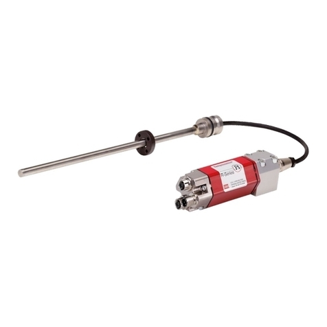
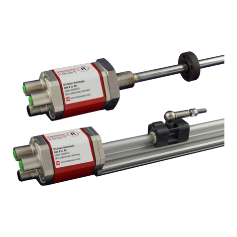
Temposonics®TH SSI ATEX / IECEx / CEC / NEC / KCs / EAC Ex certified / Japanese approval
Operation Manual
How to ensure safe commissioning
1. Protect the sensor against mechanical damage during
installation and operation.
2. Do not use damaged products and secure them against uninten-
tional commissioning. Mark damaged products as being
defective.
3. Prevent electrostatic charges.
4. Do not use the sensor in cathodic systems for corrosion
protection. Do not allow parasitic currents on the sensor housing.
5. Switch off the supply voltage prior to disconnecting or
connecting the connectors.
6. Connect the sensor very carefully and pay attention to the
polarity of connections, power supply as well as to the shape
and duration of control pulses.
7. Cable entry temperature and branching point temperature may
reach 104 °C (219 °F) and 116 °C (241 °F) respectively. Select
suitable cable and entry device.
8. For field wiring, use cables suitable for the service temperature
range of −40 °C (−40 °F) to +116 °C (241 °F).
9. Do not open when energized. Open the sensor only as shown in
Fig. 6 on page 13.
10. A seal shall be installed within 18"of the enclosure (for NEC /
CEC only).
11. Use only approved power supplies of Category II according to
IEC 61010-1.
12. Ensure that the specified permissible limit values of the sensor
for operating voltage, environmental conditions, etc. are met.
13. Make sure that:
• the sensor and associated components were installed
according to the instructions
• the sensor enclosure is clean
• all screws (only those of quality 6.8, A2-50 or A4-50 are
allowed) are tightened according to specified fastening
torque in Fig. 6
• the cable glands certified according to the required
hazardous area classification and IP protection are tightened
according to the manufacture’s specifications
• surfaces limiting the joint shall not be machined or painted
subsequently (flameproof enclosure)
• surfaces limiting the joint have not been provided with a seal
(flameproof enclosure)
• the magnet does not grind on the rod. This could cause
damage to the magnet and the sensor rod. If there is contact
between the moving magnet (including the magnet holder)
and the sensor rod, make sure that the maximum speed of the
moving magnet is less or equal 1 m/s.
14. Ground the sensor via one of the two ground lugs. Both the
sensor and the moving magnet including magnet holder must
be connected to protective ground (PE) to avoid electrostatic
discharge (ESD).
15. Before applying power, ensure that nobody’s safety is
jeopardized by starting machines.
16. Check the function of the sensor regularly and provide
documentation of the checks
(see chapter “6.2 Maintenance” on page 32).
2.4 Safety instructions for use in explosion-hazardous areas
The sensor has been designed for operation inside explosion-hazard-
ed areas. It has been tested and left the factory in a condition in which
it is safe to operate. Relevant regulations and standards have been ob-
served. According to the marking (ATEX, IECEx, CEC, NEC, KCs, EAC
Ex, Japanese approval) the sensor is approved only for operation in de-
fined hazardous areas (see chapter “2.1 Intended use” on page 3).
When do you need an external fuse?
Zone / Div. T-Series sensor
Zone 0 (rod only) External fuse required
Zone 1 / 21 No additional fuse
Zone 2 / 22 No additional fuse
Div. 1 External fuse recommended
How to install a T-Series sensor in Zone 0 according to the guide-
lines (ATEX, IECEx, CEC, NEC, KCs, EAC Ex, Japanese approval)
1. Install an external fuse in compliance with IEC 127 outside the
Ex-atmosphere. Connect it upstream to the equipment.
Current: 125 mA
2. Install the sensor housing in Zone 1, Zone 2, Zone 21 or Zone 22.
Only the rod section (for version D, G, and E) can extend into
Zone 0.
3. Follow the safety regulations detailed in IEC/EN 60079-26,
ANSI/ISA 60079-26 (12.00.03), ANSI/ISA/IEC/EN 60079-10-1 and
JNIOSH-TR-46-2 to ensure isolation between Zone 0 and Zone 1.
4. When installing the TH sensor in the boundary wall for Zone 0,
the corresponding requirements in ANSI/ISA/IEC/EN 60079-26
and ANSI/ISA/IEC/EN 60079-10-1 have to be noticed. Thereby
the screw-in thread is to be sealed air tightly (IP67) according to
ANSI/ISA/IEC/EN 60079-26 and ANSI/ISA/IEC/EN 60079-10-1.
