MTS Systems Temposonics R-Series User manual

R-Series SSI
Operation Manual
Temposonics®
Magnetostrictive Linear Position Sensors

2
Temposonics® R-Series SSI
Operation Manual
Temposonics® R-Series SSI
Operation Manual
Table of contents
1. Introduction.......................................................................................................................................................3
1.1 Purpose and use of this manual....................................................................................................................................................................3
1.2 Used symbols and warnings .........................................................................................................................................................................3
2. Safety instructions...............................................................................................................................................3
2.1 Intended use..................................................................................................................................................................................................3
2.2 Forseeable misuse.........................................................................................................................................................................................3
2.3 Installation, commissioning and operation....................................................................................................................................................4
2.4 Safety instructions for use in explosion-hazardous areas .............................................................................................................................4
2.5 Warranty........................................................................................................................................................................................................4
2.6 Return ...........................................................................................................................................................................................................4
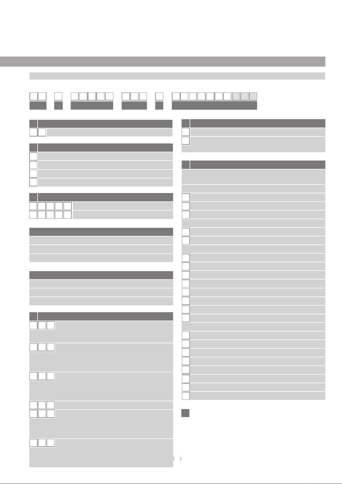
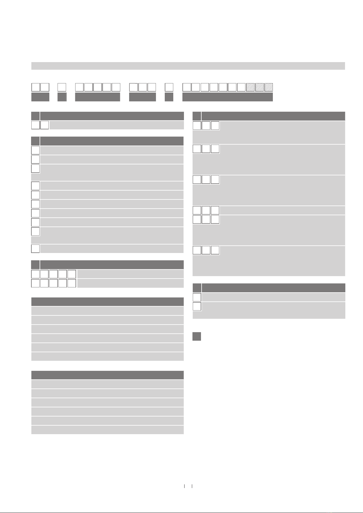
3. Identification......................................................................................................................................................5
3.1 Order code of Temposonics®RP...................................................................................................................................................................5
3.2 Order code of Temposonics®RH................................................................................................................................................................... 7
3.3 Order code of Temposonics®RD4................................................................................................................................................................. 9
3.4 Order code of Temposonics®RT4 ............................................................................................................................................................... 11
3.5 Order code of Temposonics® RF .................................................................................................................................................................13
3.6 Nameplate ...................................................................................................................................................................................................15
3.7 Approvals ....................................................................................................................................................................................................15
3.8 Scope of delivery......................................................................................................................................................................................... 15
4. Product description and commissioning ................................................................................................................... 16
4.1 Functionality and system design .................................................................................................................................................................16
4.2 Styles and installation of Temposonics® RP ................................................................................................................................................17
4.3 Styles and installation of Temposonics® RH ................................................................................................................................................18
4.4 Styles and installation of Temposonics® RD4 ..............................................................................................................................................21
4.4.1 Installation of RD4 with threaded flange ..........................................................................................................................................24
4.4.2 Installation of RD4 with pressure fit flange ........................................................................................................................................ 25
4.4.3 Installation of RD4’s sensor electronics housing ...............................................................................................................................26
4.5 Styles and installation of Temposonics® RT4...............................................................................................................................................27
4.5.1 Installation of RT4 with threaded flange.............................................................................................................................................29
4.5.2 Installation of RT4’s sensor electronics housing................................................................................................................................30
4.6 Styles and installation of Temposonics® RF.................................................................................................................................................31
4.7 Magnet installation......................................................................................................................................................................................33
4.8 Replacement of sensor................................................................................................................................................................................37
4.9 Electrical connections..................................................................................................................................................................................38
4.10 Frequently ordered accessories.................................................................................................................................................................39
5. Operation........................................................................................................................................................ 42
5.1 Getting started.............................................................................................................................................................................................42
5.2 Programming and configuration .................................................................................................................................................................42
6. Maintenance and troubleshooting .......................................................................................................................... 46
6.1 Error conditions, troubleshooting................................................................................................................................................................46
6.2 Maintenance................................................................................................................................................................................................46
6.3 Repair..........................................................................................................................................................................................................46
6.4 List of spare parts .......................................................................................................................................................................................46
6.5 Transport and storage .................................................................................................................................................................................46
7. Removal from service / dismantling........................................................................................................................ 46
8. Technical data.................................................................................................................................................. 47
8.1 Technical data of Temposonics®RP ............................................................................................................................................................47
8.2 Technical data of Temposonics® RH ............................................................................................................................................................49
8.3 Technical data of Temposonics® RD4 ..........................................................................................................................................................51
8.4 Technical data of Temposonics® RT4........................................................................................................................................................... 53
8.5 Technical data of Temposonics® RF............................................................................................................................................................. 55
9. Appendix ........................................................................................................................................................ 57

3
Temposonics® R-Series SSI
Operation Manual
Temposonics® R-Series SSI
Operation Manual
1. Introduction
1.1 Purpose and use of this manual
Before starting the operation of Temposonics®position sensors, read
this documentation thoroughly and follow the safety information.
Keep the manual for future reference!
The content of this technical documentation and of its appendix
is intended to provide information on mounting, installation and
commissioning by qualified automation personnel 1or instructed
service technicians who are familiar with the project planning and
dealing with Temposonics®position sensors.
1.2 Used symbols and warnings
Warnings are intended for your personal safety and for avoidance
of damage to the described product or connected devices. In this
documentation, safety information and warnings to avoid dangers that
might affect the life and health of operating or service personnel or
cause material damage are highlighted by the preceding pictogram,
which is defined below.
Symbol Meaning
NOTICE
This symbol is used to point to situations
that may lead to material damage, but not to
personal injury.
2. Safety instructions
2.1 Intended use
This product may be used only for the applications defined under item
1 and only in conjunction with the third-party devices and components
recommended or approved by MTS Sensors. As a prerequisite of
proper and safe operation, the product requires correct transport,
storage, mounting and commissioning and must be operated with
utmost care.
1. The sensor systems of all Temposonics®series are intended
exclusively for measurement tasks encountered in industrial,
commercial and laboratory applications. The sensors are
considered as system accessories and must be connected to
suitable evaluation electronics, e.g. a PLC, IPC, indicator or
other electronic control unit.
1/ The term qualified technical personnel characterizes persons who:
• are familiar with the safety concepts of automation technology applicable to the
particular project,
• are competent in the field of electromagnetic compatibility (EMC),
• have received adequate training for commissioning and service operations
• are familiar with the operation of the device and know the information required for
correct operation provided in the product documentation.
2.2 Forseeable misuse
Forseeable misuse Consequence
Wrong sensor connection The sensor will not work
properly or will be destroyed
Operate the sensor out of the
operating temperature range
No signal output
The sensor can be damaged
Power supply is out of the
defined range
Signal output is wrong /
no signal output /
the sensor will be damaged
Position measurement is
influenced by an external
magnetic field
Signal output is wrong
Cables are damaged
Short circuit – the sensor can
be destroyed / sensor does not
respond
Spacers are missing /
are installed in a wrong order Error in position measurement
Wrong connection
of ground / shield
Signal output is disturbed
The electronics can be damaged
Use of a magnet that is not
certified by MTS Sensors Error in position measurement
Do not step on the sensor.
The sensor might be damaged.
Do not reprocess the sensor afterwards.
The sensor might be damaged.

4
Temposonics® R-Series SSI
Operation Manual
Temposonics® R-Series SSI
Operation Manual
2.3 Installation, commissioning and operation
The position sensors must be used only in technically safe condition.
To maintain this condition and to ensure safe operation, installation,
connection and service, work may be performed only by qualified
technical personnel.
If danger of injury to persons or of damage to operating equipment
is caused by sensor failure or malfunction, additional safety measures
such as plausibility checks, limit switches, EMERGENCY STOP
systems, protective devices etc. are required. In the event of trouble,
shut down the sensor and protect it against accidental operation.
Safety instructions for commissioning
To maintain the sensor’s operability, it is mandatory to follow the
instructions given below.
1. Protect the sensor against mechanical damage during installation
and operation.
2. Do not open or dismantle the sensor.
3. Connect the sensor very carefully and pay attention to the polarity
of connections and power supply.
4. Use only approved power supplies.
5. It is indispensable to ensure that the specified permissible limit
values of the sensor for operating voltage, environmental
conditions, etc. are met.
6. Check the function of the sensor regularly and provide
documentation of the checks.
7. Before applying power, ensure that nobody’s safety is jeopardized
by starting machines.
2.4 Safety instructions for use in explosion-hazardous areas
The sensor is not suitable for operation in explosion-hazardous areas.
2.5 Warranty
MTS Sensors grants a warranty period for the Temposonics®
position sensors and supplied accessories relating to material
defects and faults that occur despite correct use in accordance with
the intended application 2. The MTS Sensors obligation is limited to
repair or replacement of any defective part of the unit. No warranty
can be provided for defects that are due to improper use or above
average stress of the product, as well as for wear parts. Under no
circumstances will MTS Sensors accept liability in the event of offense
against the warranty rules, no matter if these have been assured or
expected, even in case of fault or negligence of the company.
MTS Sensors explicitly excludes any further warranties. Neither
the company’s representatives, agents, dealers nor employees are
authorized to increase or change the scope of warranty.
2/ See also applicable MTS Sensors terms of sales and delivery on
www.mtssensors.com
2.6 Return
For diagnostic purposes, the sensor can be returned to MTS Sensors.
Any shipment cost is the responsibility of the sender 2. For a
corresponding form, see chapter “9. Appendix” on page 57.

5
Temposonics® R-Series SSI
Operation Manual
Temposonics® R-Series SSI
Operation Manual
3. Identification
3.1 Order code of Temposonics®RP
R P
a b c d e
b Design
GMagnet slider, joint on top, backlash free (part no. 253 421)
MU-magnet, OD33 (part no. 251 416-2)
SMagnet slider, joint on top (part no. 252 182)
VMagnet slider, joint at front (part no. 252 184)
f Output
S (14) (15) (16) (17) (18) (19) (20) (21) (22)
= Synchronous Serial Interface
Data length (box no. 14)
125 bit
224 bit
326 bit
Output format (box no. 15)
BBinary
GGray
Resolution (box no. 16)
10.005 mm
20.01 mm
30.05 mm
40.1 mm
50.02 mm
60.002 mm
80.001 mm
90.0005 mm
Filtering performance (box no. 17)
ANo filter + error delay (4 cycles)
CNo filter + error delay (8 cycles)
1Standard (no filters)
8Noise reduction filter (8 measurements)
DNo filter + error delay (10 cycles)
GNoise reduction filter (8 measurements) + error delay (10 cycles)
KPeak reduction filter (8 measurements)
NPeak reduction filter (8 measurements) + error delay (10 cycles)
S
f
20, 21, 22: Optional
d Connection type
D 7 0 M16 (7 pin) male connector
See “Frequently ordered accessories” for cable
connector specifications
FX X XX m PUR cable (part no. 530 045)
F01…F10 (1…10 m / 3…33 ft.) 3
See “Frequently ordered accessories” for cable
specifications
HX X XX m PUR cable (part no. 530 052)
H01…H10 (1…10 m / 3…33 ft.) 3
See “Frequently ordered accessories” for cable
specifications
M S 0 MS0 (10 pin) male connector
PXXXX m TMPU cable (part no. 530 029)
P01…P10 (1…10 m / 3…33 ft.) 3
See “Frequently ordered accessories” for cable
specifications
RX X XX m PVC cable (part no. 530 032)
R01…R10 (1…10 m / 3…33 ft.) 3
See “Frequently ordered accessories” for cable
specifications
e Operating voltage
1+24 VDC (−15 / +20 %)
A+24 VDC (−15 / +20 %), vibration resistant
(stroke length 25…2000 mm / 1…79 in.)
a Sensor model
R P Profile
.
c Stroke length
X X X X M 0025…5080 mm
X X X X U001.0…200.0 in.
Standard stroke length (mm)*
Stroke length Ordering steps
25 … 500 mm 25 mm
500…2500 mm 50 mm
2500…5080 mm 100 mm
Standard stroke length (in.)*
Stroke length Ordering steps
1 … 20 in. 1 in.
20…100 in. 2 in.
100…200 in. 4 in.
.
*/ Non standard stroke lengths are available; must be encoded in 5 mm / 0.1 in.
increments
3/ Encode in meters if using metric stroke length. Encode in feet if using US customary
stroke length
1 2 3 4 5 6 7 8 9 10 11 12 13 14 15 16 17 18 19 20 21 22
fContinued on next page

6
Temposonics® R-Series SSI
Operation Manual
Temposonics® R-Series SSI
Operation Manual
Measurement contents (optional: box no. 20)
Note: Choose “9” in box no. 18 and 19.
1Position measurement
2Differentiation measurement 4
3Velocity measurement
4Position measurement + temperature measurement
(only with data length = 24 bit)
5Differentiation measurement 4+ temperature measurement
(only with data length = 24 bit)
6Velocity measurement + temperature measurement
(only with data length = 24 bit)
Direction and sync. mode (optional: box no. 21)
Note: Choose “9” in box no. 18 and 19.
1Measuring direction forward, asynchronous mode
2Measuring direction forward, synchronous mode 1
3Measuring direction forward, synchronous mode 2
4Measuring direction forward, synchronous mode 3
5Measuring direction reverse, asynchronous mode
6Measuring direction reverse, synchronous mode 1
7Measuring direction reverse, synchronous mode 2
8Measuring direction reverse, synchronous mode 3
Internal linearization & diagnostics (optional: box no. 22)
Note: Choose “9” in box no. 18 and 19.
0No further options
1Internal linearization
2Additional alarm bit + parity even bit
(not available for temperature output, only with data length =
24 bit)
4Additional alarm bit + parity even bit and internal linearization
(not available for temperature output, only with data length =
24 bit)
4/ You need a second magnet for differentiation measurement
f Output (continued)
Signal options (box no. 18, 19)
0 0 Measuring direction forward, asynchronous mode
0 1 Measuring direction reverse, asynchronous mode
0 2 Measuring direction forward, synchronous mode 1
05Measuring direction forward, asynchronous mode,
bit 25 = alarm, bit 26 = parity even
16Measuring direction forward, asynchronous mode ,
internal linearization
9 9 Write “9” in box no. 18 and 19 for using further
combinations in boxes 20, 21, 22.

7
Temposonics® R-Series SSI
Operation Manual
Temposonics® R-Series SSI
Operation Manual
3.2 Order code of Temposonics®RH
R H
a b c d e
b Design
BBase unit
DThreaded flange M18×1.5-6g (bushing on rod end)
HThreaded flange ¾"-16 UNF-3A
(with fluoroelastomer housing-seal)
JThreaded flange M22×1.5-6g (rod Ø 12.7 mm, 800 bar)
MThreaded flange M18×1.5-6g (standard)
RThreaded flange M18×1.5-6g (thread M4 at rod end)
SThreaded flange ¾"-16 UNF-3A (standard)
TThreaded flange ¾"-16 UNF-3A (with raised-face)
UThreaded flange ¾"-16 UNF-3A
(with raised-face & fluoroelastomer housing-seal)
VThreaded flange M18×1.5-6g (with fluoroelastomer housing-seal)
S
f
20, 21, 22: Optional
a Sensor model
R H Rod
Standard stroke length (mm)*
Stroke length Ordering steps
25 … 500 mm 5 mm
500 … 750 mm 10 mm
750…1000 mm 25 mm
1000…2500 mm 50 mm
2500…5000 mm 100 mm
5000…7620 mm 250 mm
Standard stroke length (in.)*
Stroke length Ordering steps
1 … 20 in. 0.2 in.
20 … 30 in. 0.4 in.
30 … 40 in. 1.0 in.
40…100 in. 2.0 in.
100…200 in. 4.0 in.
200…300 in. 10.0 in.
c Stroke length
X X X X M 0025…7620 mm
X X X X U001.0…300.0 in.
.e Operating voltage
1+24 VDC (−15 / +20 %)
A+24 VDC (−15 / +20 %), vibration resistant
(stroke length 25…2000 mm / 1…79 in.)
*/ Non standard stroke lengths are available; must be encoded in 5 mm / 0.1 in.
increments
5/ Encode in meters if using metric stroke length. Encode in feet if using US customary
stroke length
1 2 3 4 5 6 7 8 9 10 11 12 13 14 15 16 17 18 19 20 21 22
fSee next page
d Connection type
D 7 0 M16 (7 pin) male connector
See “Frequently ordered accessories” for cable
connector specifications
FX X XX m PUR cable (part no. 530 045)
F01…F10 (1…10 m / 3…33 ft.) 5
See “Frequently ordered accessories” for cable
specifications
HX X XX m PUR cable (part no. 530 052)
H01…H10 (1…10 m / 3…33 ft.) 5
See “Frequently ordered accessories” for cable
specifications
M S 0 MS0 (10 pin) male connector
PXXXX m TMPU cable (part no. 530 029)
P01…P10 (1…10 m / 3…33 ft.) 5
See “Frequently ordered accessories” for cable
specifications
RX X XX m PVC cable (part no. 530 032)
R01…R10 (1…10 m / 3…33 ft.) 5
See “Frequently ordered accessories” for cable
specifications

8
Temposonics® R-Series SSI
Operation Manual
Temposonics® R-Series SSI
Operation Manual
6/ You need a second magnet for differentiation measurement
Signal options (box no. 18, 19)
0 0 Measuring direction forward, asynchronous mode
0 1 Measuring direction reverse, asynchronous mode
0 2 Measuring direction forward, synchronous mode 1
05Measuring direction forward, asynchronous mode,
bit 25 = alarm, bit 26 = parity even
16Measuring direction forward, asynchronous mode ,
internal linearization
9 9 Write “9” in box no. 18 and 19 for using further
combinations in boxes 20, 21, 22.
Filtering performance (box no. 17)
ANo filter + error delay (4 cycles)
CNo filter + error delay (8 cycles)
1Standard (no filters)
8Noise reduction filter (8 measurements)
DNo filter + error delay (10 cycles)
GNoise reduction filter (8 measurements) + error delay (10 cycles)
KPeak reduction filter (8 measurements)
NPeak reduction filter (8 measurements) + error delay (10 cycles)
f Output (continued)
Measurement contents (optional: box no. 20)
Note: Choose “9” in box no. 18 and 19.
1Position measurement
2Differentiation measurement 6
3Velocity measurement
4Position measurement + temperature measurement
(only with data length = 24 bit)
5Differentiation measurement 6+ temperature measurement
(only with data length = 24 bit)
6Velocity measurement + temperature measurement
(only with data length = 24 bit)
Direction and sync. mode (optional: box no. 21)
Note: Choose “9” in box no. 18 and 19.
1Measuring direction forward, asynchronous mode
2Measuring direction forward, synchronous mode 1
3Measuring direction forward, synchronous mode 2
4Measuring direction forward, synchronous mode 3
5Measuring direction reverse, asynchronous mode
6Measuring direction reverse, synchronous mode 1
7Measuring direction reverse, synchronous mode 2
8Measuring direction reverse, synchronous mode 3
Internal linearization & diagnostics (optional: box no. 22)
Note: Choose “9” in box no. 18 and 19.
0No further options
1Internal linearization
2Additional alarm bit + parity even bit
(not available for temperature output, only with data length =
24 bit)
4Additional alarm bit + parity even bit and internal linearization
(not available for temperature output, only with data length =
24 bit)
f Output
S (14) (15) (16) (17) (18) (19) (20) (21) (22)
= Synchronous Serial Interface
Data length (box no. 14)
125 bit
224 bit
326 bit
Output format (box no. 15)
BBinary
GGray
Resolution (box no. 16)
10.005 mm
20.01 mm
30.05 mm
40.1 mm
50.02 mm
60.002 mm
80.001 mm
90.0005 mm

9
Temposonics® R-Series SSI
Operation Manual
Temposonics® R-Series SSI
Operation Manual
b Design
CThreaded flange M18×1.5-6g, A/F 46
DThreaded flange ¾"-16 UNF-3A, A/F 46
GThreaded flange M18×1.5-6g, A/F 24
MThreaded flange M18×1.5-6g, A/F 23
SPressure fit flange Ø 26.9 mm f6
TThreaded flange ¾"-16 UNF-3A, A/F 23
a Sensor model
R D 4Detached sensor electronics
c Integral cable of sensor rod
For side cable entry on sensor electronics housing
D 1 SPUR cable with M16 connector,
length 250 mm (9.8 in.)
D 2 SPUR cable with M16 connector,
length 400 mm (15.7 in.)
D3SPUR cable with M16 connector,
length 600 mm (23.6 in.)
For bottom cable entry on sensor electronics housing
R2BPUR cable / wires with flat connector,
length 65 mm (2.6 in.)
R 4 BPUR cable / wires with flat connector,
length 170 mm (6.7 in.)
R5BPUR cable / wires with flat connector,
length 230 mm (9.1 in.)
R6BPUR cable / wires with flat connector,
length 350 mm (13.8 in.)
RD4S
a b c d e f
23, 24, 25: Optional
Operating voltage
+24 VDC (−15 / +20 %); Standard, not indicated in order code
d Stroke length
XXX X MFlange »C« / »D«, »G«, »M« / »T«:
0025…5080 mm
Flange »S«:
0025…2540 mm
X X X X U Flange »C« / »D«, »G«, »M« / »T«:
001.0…200.0 in.
Flange »S«:
001.0…100.0 in.
.
Standard stroke length (mm)*
Stroke length Ordering steps
25 … 500 mm 5 mm
500 … 750 mm 10 mm
750…1000 mm 25 mm
1000…2500 mm 50 mm
2500…5080 mm 100 mm
Standard stroke length (in.)*
Stroke length Ordering steps
1 … 20 in. 0.2 in.
20 … 30 in. 0.4 in.
30 … 40 in. 1.0 in.
40…100 in. 2.0 in.
100…200 in. 4.0 in.
*/ Non standard stroke lengths are available; must be encoded in 5 mm / 0.1 in.
increments
7/ Encode in meters if using metric stroke length. Encode in feet if using US customary
stroke length
1 2 3 4 5 6 7 8 9 10 11 12 13 14 15 16 17 18 19 20 21 22 23 24 25
3.3 Order code of Temposonics®RD4
fContinued on next page
e Connection type
D 7 0 M16 (7 pin) male connector
See “Frequently ordered accessories” for cable
connector specifications
FX X XX m PUR cable (part no. 530 045)
F01…F10 (1…10 m / 3…33 ft.) 7
See “Frequently ordered accessories” for cable
specifications
HX X XX m PUR cable (part no. 530 052)
H01…H10 (1…10 m / 3…33 ft.) 7
See “Frequently ordered accessories” for cable
specifications
M S 0 MS0 (10 pin) male connector
PXXXX m TMPU cable (part no. 530 029)
P01…P10 (1…10 m / 3…33 ft.) 7
See “Frequently ordered accessories” for cable
specifications
RX X XX m PVC cable (part no. 530 032)
R01…R10 (1…10 m / 3…33 ft.) 7
See “Frequently ordered accessories” for cable
specifications

10
Temposonics® R-Series SSI
Operation Manual
Temposonics® R-Series SSI
Operation Manual
f Output
S (17) (18) (19) (20) (21) (22) (23) (24) (25)
= Synchronous Serial Interface
Data length (box no. 17)
125 bit
224 bit
326 bit
Output format (box no. 18)
BBinary
GGray
Resolution (box no. 19)
10.005 mm
20.01 mm
30.05 mm
40.1 mm
50.02 mm
60.002 mm
80.001 mm
Filtering performance (box no. 20)
ANo filter + error delay (4 cycles)
CNo filter + error delay (8 cycles)
1Standard (no filters)
8Noise reduction filter (8 measurements)
DNo filter + error delay (10 cycles)
GNoise reduction filter (8 measurements) + error delay (10 cycles)
KPeak reduction filter (8 measurements)
NPeak reduction filter (8 measurements) + error delay (10 cycles)
Signal options (box no. 21, 22)
0 0 Measuring direction forward, asynchronous mode
0 1 Measuring direction reverse, asynchronous mode
0 2 Measuring direction forward, synchronous mode 1
05Measuring direction forward, asynchronous mode,
bit 25 = alarm, bit 26 = parity even
9 9 Write “9” in box no. 21 and 22 for using further
combinations in boxes 23, 24, 25.
f Output (continued)
Measurement contents (optional: box no. 23)
Note: Choose “9” in box no. 21 and 22.
1Position measurement
2Differentiation measurement 8
3Velocity measurement
4Position measurement + temperature measurement
(only with data length = 24 bit)
5Differentiation measurement 8+ temperature measurement
(only with data length = 24 bit)
6Velocity measurement + temperature measurement
(only with data length = 24 bit)
Direction and sync. mode (optional: box no. 24)
Note: Choose “9” in box no. 21 and 22.
1Measuring direction forward, asynchronous mode
2Measuring direction forward, synchronous mode 1
3Measuring direction forward, synchronous mode 2
4Measuring direction forward, synchronous mode 3
5Measuring direction reverse, asynchronous mode
6Measuring direction reverse, synchronous mode 1
7Measuring direction reverse, synchronous mode 2
8Measuring direction reverse, synchronous mode 3
Only available for flanges »C« / »D«, »G« & »M« / »T«
Internal linearization & diagnostics (optional: box no. 25)
Note: Choose “9” in box no. 21 and 22.
0No further options
1Internal linearization
2Additional alarm bit + parity even bit
(not available for temperature output, only with data length
= 24 bit)
4Additional alarm bit + parity even bit and internal linearization
(not available for temperature output, only with data length
= 24 bit)
8/ You need a second magnet for differentiation measurement

11
Temposonics® R-Series SSI
Operation Manual
Temposonics® R-Series SSI
Operation Manual
3.4 Order code of Temposonics®RT4
Standard stroke length (mm)*
Stroke length Ordering steps
25 … 500 mm 5 mm
500 … 750 mm 10 mm
750…1000 mm 25 mm
1000…2540 mm 50 mm
Standard stroke length (in.)*
Stroke length Ordering steps
1 … 20 in. 0.2 in.
20 … 30 in. 0.4 in.
30 … 40 in. 1.0 in.
40…100 in. 2.0 in.
d Stroke length
X X X X M 0025...2540 mm
X X X X U001.0...100.0 in
b Design
D Threaded flange with flat-face, ¾"-16 UNF-3A
MThreaded flange with flat-face, M18×1.5-6g
TThreaded flange with raised-face, ¾"-16 UNF-3A
a Sensor model
R T 4 Redundant with detached electronics
c Integral cable of sensor rod
For side cable entry on sensor electronics housing
B 1 E 250 mm (9.8 in.) Santoprene®cable,
hanging connector
B 2 E 400 mm (15.7 in.) Santoprene®cable,
hanging connector
B3 E 600 mm (23.6 in.) Santoprene®cable,
hanging connector
Operating voltage
+24 VDC (−15 / +20 %); Standard, not indicated in order code
f Output
S (17) (18) (19) (20) (21) (22) (23) (24) (25)
= Synchronous Serial Interface
Data length (box no. 17)
125 bit
224 bit
326 bit
Output format (box no. 18)
BBinary
G Gray
Resolution (box no. 19)
10.005 mm
20.01 mm
30.05 mm
40.1 mm
50.02 mm
60.002 mm
80.001 mm
e Connection type
D 7 0 M16 (7 pin) male connector
See “Frequently ordered accessories” for cable
connector specifications
FX X XX m PUR cable (part no. 530 045)
F01…F30 (1…30 m / 3…98 ft.) 9
See “Frequently ordered accessories” for cable
specifications
M S 0 MS (10 pin) male connector
PX X XX m TMPU cable (part no. 530 029)
P01…P30 (1…30 m / 3…98 ft.) 9
See “Frequently ordered accessories” for cable
specifications
RX X XX m PVC cable (part no. 530 032)
R01…R30 (1…30 m / 3…98 ft.) 9
See “Frequently ordered accessories” for cable
specifications
*/ Non standard stroke lengths are available; must be encoded in 5 mm / 0.1 in.
increments
9/ Encode in meters if using metric stroke length. Encode in feet if using US customary
stroke length
fContinued on next page
RT4B E S
a b c d e f
23, 24, 25: Optional
1 2 3 4 5 6 7 8 9 10 11 12 13 14 15 16 17 18 19 20 21 22 23 24 25

12
Temposonics® R-Series SSI
Operation Manual
Temposonics® R-Series SSI
Operation Manual
f Output (continued)
Filtering performance (box no. 20)
8Noise reduction filter (8 measurements)
GNoise reduction filter (8 measurements) + error delay (10 cycles)
Signal options (box no. 21, 22)
0 0 Measuring direction forward, asynchronous mode
0 1 Measuring direction reverse, asynchronous mode
0 2 Measuring direction forward, synchronous mode 1
05Measuring direction forward, asynchronous mode,
bit 25 = alarm, bit 26 = parity even
9 9 Write “9” in box no. 21 and 22 for using further
combinations in boxes 23, 24, 25.
Measurement contents (optional: box no. 23)
Note: Choose “9” in box no. 21 and 22.
1Position measurement
Direction and sync. mode (optional: box no. 24)
Note: Choose “9” in box no. 21 and 22.
1Measuring direction forward, asynchronous mode
2Measuring direction forward, synchronous mode 1
5Measuring direction reverse, asynchronous mode
6Measuring direction reverse, synchronous mode 1
Diagnostics (optional: box no. 25)
Note: Choose “9” in box no. 21 and 22.
0No further options
2Additional alarm bit + parity even bit

13
Temposonics® R-Series SSI
Operation Manual
Temposonics® R-Series SSI
Operation Manual
3.5 Order code of Temposonics® RF
R F 1
a b c d e
S
f
21, 22, 23: Optional
b Design
CBase unit
MThreaded flange M18×1.5-6g
SThreaded flange ¾"-16 UNF-3A
a Sensor model
R F Flexible sensor rod
e Operating voltage
1+24 VDC (−15 / +20 %)
*/ Non standard stroke lengths are available; must be encoded in 5 mm / 0.1 in.
increments
10/ Encode in meters if using metric stroke length. Encode in feet if using US customary
stroke length
c Stroke length
X X X X X M00150…20,000 mm
X X X X X U0006.0…0787.0 in.
Standard stroke length (mm)*
Stroke length Ordering steps
150 … 1000 mm 50 mm
1000 … 5000 mm 100 mm
5000 …10,000 mm 250 mm
10,000…15,000 mm 500 mm
> 15,000 mm 1000 mm
Standard stroke length (in.)*
Stroke length Ordering steps
6 … 40 in. 2 in.
40…197 in. 4 in.
197…394 in. 10 in.
394…591 in. 20 in.
> 591 in. 40 in.
1 2 3 4 5 6 7 8 9 10 11 12 13 14 15 16 17 18 19 20 21 22 23
fContinued on next page
d Connection type
D 7 0 M16 (7 pin) male connector
See “Frequently ordered accessories” for cable
connector specifications
FX X XX m PUR cable (part no. 530 045)
F01…F10 (1…10 m / 3…33 ft.) 10
See “Frequently ordered accessories” for cable
specifications
HX X XX m PUR cable (part no. 530 052)
H01…H10 (1…10 m / 3…33 ft.) 10
See “Frequently ordered accessories” for cable
specifications
M S 0 MS0 (10 pin) male connector
PXXXX m TMPU cable (part no. 530 029)
P01…P10 (1…10 m / 3…33 ft.) 10
See “Frequently ordered accessories” for cable
specifications
RX X XX m PVC cable (part no. 530 032)
R01…R10 (1…10 m / 3…33 ft.) 10
See “Frequently ordered accessories” for cable
specifications

14
Temposonics® R-Series SSI
Operation Manual
Temposonics® R-Series SSI
Operation Manual
f Output (continued)
Measurement contents (optional: box no. 21)
Note: Choose “9” in box no. 19 and 20.
1Position measurement
2Differentiation measurement 11
3Velocity measurement
4Position measurement + temperature measurement
(only with data length = 24 bit)
5Differentiation measurement 11 + temperature measurement
(only with data length = 24 bit)
6Velocity measurement + temperature measurement
(only with data length = 24 bit)
Direction and sync. mode (optional: box no. 22)
Note: Choose “9” in box no. 19 and 20.
1Measuring direction forward, asynchronous mode
2Measuring direction forward, synchronous mode 1
3Measuring direction forward, synchronous mode 2
4Measuring direction forward, synchronous mode 3
5Measuring direction reverse, asynchronous mode
6Measuring direction reverse, synchronous mode 1
7Measuring direction reverse, synchronous mode 2
8Measuring direction reverse, synchronous mode 3
Diagnostics (optional: box no. 23)
Note: Choose “9” in box no. 19 and 20.
0No further options
2Additional alarm bit + parity even bit
(not available for temperature output, only with data length =
24 bit)
11/ You need a second magnet for differentiation measurement
Signal options (box no. 19, 20)
0 0 Measuring direction forward, asynchronous mode
0 1 Measuring direction reverse, asynchronous mode
0 2 Measuring direction forward, synchronous mode 1
05Measuring direction forward, asynchronous mode,
bit 25 = alarm, bit 26 = parity even
9 9 Write “9” in box no. 19 and 20 for using further
combinations in boxes 21, 22, 23.
f Output
S (15) (16) (17) (18) (19) (20) (21) (22) (23)
= Synchronous Serial Interface
Data length (box no. 15)
125 bit
224 bit
326 bit
Output format (box no. 16)
BBinary
GGray
Resolution (box no. 17)
10.005 mm
20.01 mm
30.05 mm
40.1 mm
50.02 mm
60.002 mm
Filtering performance (box no. 18)
ANo filter + error delay (4 cycles)
CNo filter + error delay (8 cycles)
1Standard (no filters)
8Noise reduction filter (8 measurements)
DNo filter + error delay (10 cycles)
GNoise reduction filter (8 measurements) + error delay (10 cycles)
KPeak reduction filter (8 measurements)
NPeak reduction filter (8 measurements) + error delay (10 cycles)

15
Temposonics® R-Series SSI
Operation Manual
Temposonics® R-Series SSI
Operation Manual
3.6 Nameplate
3.7 Approvals
certified (RP / RH / RF), UL approved (RP / RH),
GOST certified (RP / RH / RD4 / RF)
3.8 Scope of delivery
RP (profile sensor):
• Sensor, position magnet
• 2 mounting clamps up to 1250 mm (50 in.) stroke length +
1 mounting clamp for each 500 mm (20 in.) additional stroke length
RH (rod sensor):
• RH-B: Base unit, 2 socket screws M4
• RH-D / -H / -J / -M / -R / -S / -T / -U / -V: Sensor, O-ring
RD4 (detached sensor electronics):
• RD4-C / -D / -G / -M / -T: Sensor, O-ring
• RD4-S: Sensor, O-ring, back-up ring
RT4 (redundant with detached electronics):
• Sensor, O-ring
RF (flexible sensor rod):
• RF-C: Base unit
• RF-M /-S: Sensor, O-ring
Fig. 1: Example of a nameplate of a RH sensor (production site Germany)
Fig. 2: Example of a nameplate of a RH sensor (production site USA)
Order code
Serial number
Coding
output dependent
RHM0425MD701S1G2100
0.01 mm / 25 Bit gray
Grd.: 2797.14 m/s
FNr.: 1413 3950
1237584838239380239842390759348759872
Order code
Serial number
Coding
output dependent
RHT0060UD701S1B1C02
S/N: 90787117
GRD: 9.1132 uS/In 2787.16 m/s
90787117907871179078711790787117

16
Temposonics® R-Series SSI
Operation Manual
Temposonics® R-Series SSI
Operation Manual
4. Product description and commissioning
4.1 Functionality and system design
Product designation
• Position sensor Temposonics®R-Series
Sensor model
• Temposonics®RP (profile sensor)
• Temposonics®RH (rod sensor)
• Temposonics®RD4 (detached sensor electronics)
• Temposonics®RT4 (redundant with detached sensor electronics)
• Temposonics®RF (flexible sensor rod)
Stroke length
• RP 25… 5080 mm (1.0…200.0 in.)
• RH 25… 7620 mm (1.0…300.0 in.)
• RD4 25… 5080 mm (1.0…200.0 in.)
• RT4 25… 2540 mm (1.0…100.0 in.)
• RF 150…20,000 mm (6.0…787.0 in.)
Output signal
• SSI
Application
Temposonics®position sensors are used for measurement and con-
version of the length (position) variable in the fields of automated sys-
tems and mechanical engineering.
Principle of operation and system construction
The absolute, linear position sensors provided by MTS Sensors
rely on the company’s proprietary Temposonics®magnetostrictive
technology, which can determine position with a high level of
precision and robustness. Each Temposonics®position sensor
consists of a ferromagnetic waveguide, a position magnet, a strain
pulse converter and supporting electronics. The magnet, connected
to the object in motion in the application, generates a magnetic field
at its location on the waveguide. A short current pulse is applied to
the waveguide. This creates a momentary radial magnetic field and
torsional strain on the waveguide. The momentary interaction of the
magnetic fields releases a torsional strain pulse that propagates the
length of the waveguide. When the ultrasonic wave reaches the end of
the waveguide it is converted into an electrical signal. Since the speed
of the ultrasonic wave in the waveguide is precisely known, the time
required to receive the return signal can be converted into a linear
position measurement with both high accuracy and repeatability.
Modular mechanical and electronic construction
• The sensor rod or profile protects the inner sensor element.
• The sensor electronics housing, a rugged aluminum construction,
contains the complete electronic interface with active signal
conditioning. Double shielding ensures high safety of operation and
optimum EMC (Electromagnetic Compatibility).
• The external position magnet is a permanent magnet. Mounted on
the mobile machine part, it travels along the sensor rod or profile
and triggers the measurement through the sensor rod wall.
• The sensor can be connected directly to a control system. Its
electronics generates a strictly position proportional signal output
between start and end position.
Fig. 3: Time-of-flight based magnetostrictive position sensing principle
5
Sensing element
(Waveguide)
Position magnet (Magnetic field) Torsional strain
pulse converter
4
Current pulse
generates
magnetic field
Interaction with
position magnet
field generates
torsional strain
pulse Torsional strain
pulse propagates
Strain pulse
detected by
converter
Time-of-flight converted
into position
1
2
3

17
Temposonics® R-Series SSI
Operation Manual
Temposonics® R-Series SSI
Operation Manual
4.2 Styles and installation of Temposonics® RP
Fig. 4: Temposonics®RP with U-magnet
Installation of RP
The position sensor can be installed in any position. Normally, the
sensor is firmly installed and the position magnet is fastened to the
mobile machine part. Thus it can travel along the sensor profile. The
sensor is fitted on a flat machine surface using the mounting clamps
(Fig. 5). A length-dependent number of these clamps is delivered with
the sensor and must be distributed over the profile at regular distances.
For fastening use M5×20 screws to DIN 6912 that should be tightened
with a fastening torque of 5 Nm.
Fig. 5: Mounting clamps (part no. 400 802) with cylinder screw M5×20
Controlling design dimensions are in millimeters and measurements in ( ) are in inches
Fig. 6: T-slot nut M5 (part no. 401 602)
NOTICE
Take care to mount the sensor in an axially parallel
position to avoid damage to magnet and sensor.
Alternative: If only limited space is available, the profile sensor can be
mounted also via the T-rail in the profile bottom using an T-slot nut M5
(part no. 401 602) or a sliding block (Fig. 6).
Fastening torque: 5 Nm
50
(1.97)
9.5
(0.38)
Bore Ø 5.5
(Ø 0.27)
14.5
(0.57)
≤ 5
(≤ 0.2)
M5
RP-M, example: Connector outlet D70
Ø 5.5
(Ø 0.22)
9
(0.36)
68 (2.68)
2
(0.08)
50 (1.97)
35.6 (1.4)
Dead zone
66 / 71*
(2.6 / 2.8*)
Stroke length
25…5080
(1…200)
Dead zone
66 / 71*
(2.6 / 2.8*)
Stroke length
25…5080
(1…200)
Sensor electronics housing
75.2
(2.96)
12
(0.47)
32.5
(1.28)
Sensor electronics housing
96
(3.78)
28
(1.1)
14.5
(0.57)
28
(1.1)
28
(1.1)
Adjustable mounting clamp
Ø 5.5
(Ø 0.22)
9
(0.36)
68 (2.68)
2
(0.08)
50 (1.97)
35.6 (1.4)
e.g. for M5 or
#10 screws
M4×0.7-6g
Non-magnetic
mounting support
14.5
(0.57)
Null zone
28
(1.1)
Null zone
49 (1.93)
45
(1.77)
49 (1.93)
45 (1.77)
Magnet
Magnet
* Stroke length > 5000 mm (196.9 in.)
e.g. for M5 or
#10 screws
RP-M, example: Cable outlet FXX / HXX / PXX / RXX
Ø 5.5
(Ø 0.22)
9
(0.36)
68 (2.68)
2
(0.08)
50 (1.97)
35.6 (1.4)
Dead zone
66 / 71*
(2.6 / 2.8*)
Stroke length
25…5080
(1…200)
Dead zone
66 / 71*
(2.6 / 2.8*)
Stroke length
25…5080
(1…200)
Sensor electronics housing
75.2
(2.96)
12
(0.47)
32.5
(1.28)
Sensor electronics housing
96
(3.78)
28
(1.1)
14.5
(0.57)
28
(1.1)
28
(1.1)
Adjustable mounting clamp
Ø 5.5
(Ø 0.22)
9
(0.36)
68 (2.68)
2
(0.08)
50 (1.97)
35.6 (1.4)
e.g. for M5 or
#10 screws
M4×0.7-6g
Non-magnetic
mounting support
14.5
(0.57)
Null zone
28
(1.1)
Null zone
49 (1.93)
45
(1.77)
49 (1.93)
45 (1.77)
Magnet
Magnet
* Stroke length > 5000 mm (196.9 in.)
e.g. for M5 or
#10 screws
Controlling design dimensions are in millimeters and measurements in ( ) are in inches

18
Temposonics® R-Series SSI
Operation Manual
Temposonics® R-Series SSI
Operation Manual
4.3 Styles and installation of Temposonics® RH
Controlling design dimensions are in millimeters and measurements in ( ) are in inches
Fig. 7: Temposonics®RH with ring magnet part 1
RH-H / -M / -S / -V, example: Cable outlet FXX / HXX / PXX / RXX
Null zone
51
(2.01)
Stroke length
25…7620
(1…300)
Null zone
51
(2.01)
Stroke length
25…7620
(1…300)
Dead zone
63.5 / 66*
(2.5 / 2.6*)
Dead zone
63.5 / 66*
(2.5 / 2.6*)
Dead zone
63.5 / 66*
(2.5 / 2.6*)
Sensor electronics housing
68
(2.68)
Ø 10 ± 0.13
(Ø 0.39 ± 0.01)
Ø
10 ± 0.13
(Ø
0.39 ± 0.01)
Stroke length
25…7620
(1…300)
Dead zone
63.5 / 66*
(2.5 / 2.6*)
Ø 10 ± 0.13
(Ø 0.39 ± 0.01)
Null zone
51
(2.01)
Sensor electronics housing
68
(2.68)
32.5
(1.28)
Flange »M« / »V«: M18×1.5-6g
Flange »H« / »S«: ¾"-16 UNF-3A
Flange »T« / »U«: ¾"-16 UNF-3A
Flange »D«: M18×1.5-6g
Flange »R«: M18×1.5-6g
Flange »J«: M22×1.5-6g
Flange »M« / »V«: M18×1.5-6g
Flange »H« / »S«: ¾"-16 UNF-3A
46
(1.81)
53
(2.09)
43.7
(1.72)
49
(1.93)
Null zone
61
(2.4)
Stroke length
25…7620
(1…300)
Stroke length
25…7620
(1…300)
Dead zone
52 / 54 / 57**
(2.05 / 2.13 / 2.24**)
Sensor electronics housing
58
(2.28)
Ø 6.8 ± 0.13
(Ø 0.27 ± 0.01)
22
(0.87)
15
(0.59)
3
(0.12)
8
(0.31)
Ø 12.8 ± 0.1
(Ø 0.5 ± 0.004)
Dead zone
70 / 72.5*
(2.76 / 2.85*)
M4 thread
Ø 10 ± 0.13
(Ø 0.39 ± 0.01)
3.5
(0.14)
6
(0.24)
Dead zone
73.6
(2.9)
Ø 12.7 ± 0.13
(Ø 0.5 ± 0.01)
Magnet
** 25…1575 mm ( 1 … 62.01 in.) stroke length: 52 mm (2.05 in.) dead zone
1576…5000 mm ( 62.05…196.90 in.) stroke length: 54 mm (2.13 in.) dead zone
5001…7620 mm (196.89…300.00 in.) stroke length: 57 mm (2.24 in.) dead zone
10
(0.38)
12
(0.46)
Magnet
MagnetMagnetMagnet
Magnet
10
(0.38)
* Stroke length
> 5000 mm (196.9 in.)
* Stroke length
> 5000 mm (196.9 in.)
* Stroke length
> 5000 mm (196.9 in.)
* Stroke length
> 5000 mm (196.9 in.)
* Stroke length
> 5000 mm (196.9 in.)
Ø 10
(Ø 0.39)
A/F 46
A/F 46
A/F 46
A/F 46
A/F 46
A/F 44.5
6.2
(0.24)
4.6
(0.18)
46
(1.81)
53
(2.09)
2.54
(0.1)
9.65
(0.38)
Ø 25.4
(Ø 1)
Null zone
51
(2.01)
11.8
(0.46)
Magnet
44.5
(1.75)
51.3
(2.02)
25
(0.98)
25
(0.98)
RH-H / -M / -S / -V, example: Connector outlet D70
Null zone
51
(2.01)
Stroke length
25…7620
(1…300)
Null zone
51
(2.01)
Stroke length
25…7620
(1…300)
Dead zone
63.5 / 66*
(2.5 / 2.6*)
Dead zone
63.5 / 66*
(2.5 / 2.6*)
Dead zone
63.5 / 66*
(2.5 / 2.6*)
Sensor electronics housing
68
(2.68)
Ø
10 ± 0.13
(Ø
0.39 ± 0.01)
Ø 10 ± 0.13
(Ø 0.39 ± 0.01)
Stroke length
25…7620
(1…300)
Dead zone
63.5 / 66*
(2.5 / 2.6*)
Ø 10 ± 0.13
(Ø 0.39 ± 0.01)
Null zone
51
(2.01)
Sensor electronics housing
68
(2.68)
32.5
(1.28)
Flange »M« / »V«: M18×1.5-6g
Flange »H« / »S«: ¾"-16 UNF-3A
Flange »T« / »U«: ¾"-16 UNF-3A
Flange »D«: M18×1.5-6g
Flange »R«: M18×1.5-6g
Flange »J«: M22×1.5-6g
Flange »M« / »V«: M18×1.5-6g
Flange »H« / »S«: ¾"-16 UNF-3A
46
(1.81)
53
(2.09)
43.7
(1.72)
49
(1.93)
Null zone
61
(2.4)
Stroke length
25…7620
(1…300)
Stroke length
25…7620
(1…300)
Dead zone
52 / 54 / 57**
(2.05 / 2.13 / 2.24**)
Sensor electronics housing
58
(2.28)
Ø 6.8 ± 0.13
(Ø 0.27 ± 0.01)
22
(0.87)
15
(0.59)
3
(0.12)
8
(0.31)
Ø 12.8 ± 0.1
(Ø 0.5 ± 0.004)
Dead zone
70 / 72.5*
(2.76 / 2.85*)
M4 thread
Ø 10 ± 0.13
(Ø 0.39 ± 0.01)
3.5
(0.14)
6
(0.24)
Dead zone
73.6
(2.9)
Ø 12.7 ± 0.13
(Ø 0.5 ± 0.01)
Magnet
** 25…1575 mm ( 1 … 62.01 in.) stroke length: 52 mm (2.05 in.) dead zone
1576…5000 mm ( 62.05…196.90 in.) stroke length: 54 mm (2.13 in.) dead zone
5001…7620 mm (196.89…300.00 in.) stroke length: 57 mm (2.24 in.) dead zone
10
(0.38)
12
(0.46)
Magnet
Magnet
MagnetMagnet
Magnet
10
(0.38)
* Stroke length
> 5000 mm (196.9 in.)
* Stroke length
> 5000 mm (196.9 in.)
* Stroke length
> 5000 mm (196.9 in.)
* Stroke length
> 5000 mm (196.9 in.)
* Stroke length
> 5000 mm (196.9 in.)
Ø 10
(Ø 0.39)
A/F 46
A/F 46
A/F 46
A/F 46
A/F 46
A/F 44.5
6.2
(0.24)
4.6
(0.18)
46
(1.81)
53
(2.09)
2.54
(0.1)
9.65
(0.38)
Ø 25.4
(Ø 1)
Null zone
51
(2.01)
11.8
(0.46)
Magnet
44.5
(1.75)
51.3
(2.02)
25
(0.98)
25
(0.98)
RH-D, example: Connector outlet D70
Null zone
51
(2.01)
Stroke length
25…7620
(1…300)
Null zone
51
(2.01)
Stroke length
25…7620
(1…300)
Dead zone
63.5 / 66*
(2.5 / 2.6*)
Dead zone
63.5 / 66*
(2.5 / 2.6*)
Dead zone
63.5 / 66*
(2.5 / 2.6*)
Sensor electronics housing
68
(2.68)
Ø 10 ± 0.13
(Ø 0.39 ± 0.01)
Ø 10 ± 0.13
(Ø 0.39 ± 0.01)
Stroke length
25…7620
(1…300)
Dead zone
63.5 / 66*
(2.5 / 2.6*)
Ø 10 ± 0.13
(Ø 0.39 ± 0.01)
Null zone
51
(2.01)
Sensor electronics housing
68
(2.68)
32.5
(1.28)
Flange »M« / »V«: M18×1.5-6g
Flange »H« / »S«: ¾"-16 UNF-3A
Flange »T« / »U«: ¾"-16 UNF-3A
Flange »D«: M18×1.5-6g
Flange »R«: M18×1.5-6g
Flange »J«: M22×1.5-6g
Flange »M« / »V«: M18×1.5-6g
Flange »H« / »S«: ¾"-16 UNF-3A
46
(1.81)
53
(2.09)
43.7
(1.72)
49
(1.93)
Null zone
61
(2.4)
Stroke length
25…7620
(1…300)
Stroke length
25…7620
(1…300)
Dead zone
52 / 54 / 57**
(2.05 / 2.13 / 2.24**)
Sensor electronics housing
58
(2.28)
Ø 6.8 ± 0.13
(Ø 0.27 ± 0.01)
22
(0.87)
15
(0.59)
3
(0.12)
8
(0.31)
Ø 12.8 ± 0.1
(Ø 0.5 ± 0.004)
Dead zone
70 / 72.5*
(2.76 / 2.85*)
M4 thread
Ø 10 ± 0.13
(Ø 0.39 ± 0.01)
3.5
(0.14)
6
(0.24)
Dead zone
73.6
(2.9)
Ø 12.7 ± 0.13
(Ø 0.5 ± 0.01)
Magnet
** 25…1575 mm ( 1 … 62.01 in.) stroke length: 52 mm (2.05 in.) dead zone
1576…5000 mm ( 62.05…196.90 in.) stroke length: 54 mm (2.13 in.) dead zone
5001…7620 mm (196.89…300.00 in.) stroke length: 57 mm (2.24 in.) dead zone
10
(0.38)
12
(0.46)
Magnet
Magnet
Magnet
Magnet
Magnet
10
(0.38)
* Stroke length
> 5000 mm (196.9 in.)
* Stroke length
> 5000 mm (196.9 in.)
* Stroke length
> 5000 mm (196.9 in.)
* Stroke length
> 5000 mm (196.9 in.)
* Stroke length
> 5000 mm (196.9 in.)
Ø 10
(Ø 0.39)
A/F 46
A/F 46
A/F 46
A/F 46
A/F 46
A/F 44.5
6.2
(0.24)
4.6
(0.18)
46
(1.81)
53
(2.09)
2.54
(0.1)
9.65
(0.38)
Ø 25.4
(Ø 1)
Null zone
51
(2.01)
11.8
(0.46)
Magnet
44.5
(1.75)
51.3
(2.02)
25
(0.98)
25
(0.98)
RH-T / -U, example: Connector outlet D70
Null zone
51
(2.01)
Stroke length
25…7620
(1…300)
Null zone
51
(2.01)
Stroke length
25…7620
(1…300)
Dead zone
63.5 / 66*
(2.5 / 2.6*)
Dead zone
63.5 / 66*
(2.5 / 2.6*)
Dead zone
63.5 / 66*
(2.5 / 2.6*)
Sensor electronics housing
68
(2.68)
Ø 10 ± 0.13
(Ø 0.39 ± 0.01)
Ø 10 ± 0.13
(Ø 0.39 ± 0.01)
Stroke length
25…7620
(1…300)
Dead zone
63.5 / 66*
(2.5 / 2.6*)
Ø 10 ± 0.13
(Ø 0.39 ± 0.01)
Null zone
51
(2.01)
Sensor electronics housing
68
(2.68)
32.5
(1.28)
Flange »M« / »V«: M18×1.5-6g
Flange »H« / »S«: ¾"-16 UNF-3A
Flange »T« / »U«: ¾"-16 UNF-3A
Flange »D«: M18×1.5-6g
Flange »R«: M18×1.5-6g
Flange »J«: M22×1.5-6g
Flange »M« / »V«: M18×1.5-6g
Flange »H« / »S«: ¾"-16 UNF-3A
46
(1.81)
53
(2.09)
43.7
(1.72)
49
(1.93)
Null zone
61
(2.4)
Stroke length
25…7620
(1…300)
Stroke length
25…7620
(1…300)
Dead zone
52 / 54 / 57**
(2.05 / 2.13 / 2.24**)
Sensor electronics housing
58
(2.28)
Ø 6.8 ± 0.13
(Ø 0.27 ± 0.01)
22
(0.87)
15
(0.59)
3
(0.12)
8
(0.31)
Ø 12.8 ± 0.1
(Ø 0.5 ± 0.004)
Dead zone
70 / 72.5*
(2.76 / 2.85*)
M4 thread
Ø 10 ± 0.13
(Ø 0.39 ± 0.01)
3.5
(0.14)
6
(0.24)
Dead zone
73.6
(2.9)
Ø 12.7 ± 0.13
(Ø 0.5 ± 0.01)
Magnet
** 25…1575 mm ( 1 … 62.01 in.) stroke length: 52 mm (2.05 in.) dead zone
1576…5000 mm ( 62.05…196.90 in.) stroke length: 54 mm (2.13 in.) dead zone
5001…7620 mm (196.89…300.00 in.) stroke length: 57 mm (2.24 in.) dead zone
10
(0.38)
12
(0.46)
Magnet
MagnetMagnetMagnet
Magnet
10
(0.38)
* Stroke length
> 5000 mm (196.9 in.)
* Stroke length
> 5000 mm (196.9 in.)
* Stroke length
> 5000 mm (196.9 in.)
* Stroke length
> 5000 mm (196.9 in.)
* Stroke length
> 5000 mm (196.9 in.)
Ø 10
(Ø 0.39)
A/F 46
A/F 46
A/F 46
A/F 46
A/F 46
A/F 44.5
6.2
(0.24)
4.6
(0.18)
46
(1.81)
53
(2.09)
2.54
(0.1)
9.65
(0.38)
Ø 25.4
(Ø 1)
Null zone
51
(2.01)
11.8
(0.46)
Magnet
44.5
(1.75)
51.3
(2.02)
25
(0.98)
25
(0.98)
RH-R, example: Connector outlet D70
Null zone
51
(2.01)
Stroke length
25…7620
(1…300)
Null zone
51
(2.01)
Stroke length
25…7620
(1…300)
Dead zone
63.5 / 66*
(2.5 / 2.6*)
Dead zone
63.5 / 66*
(2.5 / 2.6*)
Dead zone
63.5 / 66*
(2.5 / 2.6*)
Sensor electronics housing
68
(2.68)
Ø 10 ± 0.13
(Ø 0.39 ± 0.01)
Ø 10 ± 0.13
(Ø 0.39 ± 0.01)
Stroke length
25…7620
(1…300)
Dead zone
63.5 / 66*
(2.5 / 2.6*)
Ø 10 ± 0.13
(Ø 0.39 ± 0.01)
Null zone
51
(2.01)
Sensor electronics housing
68
(2.68)
32.5
(1.28)
Flange »M« / »V«: M18×1.5-6g
Flange »H« / »S«: ¾"-16 UNF-3A
Flange »T« / »U«: ¾"-16 UNF-3A
Flange »D«: M18×1.5-6g
Flange »R«: M18×1.5-6g
Flange »J«: M22×1.5-6g
Flange »M« / »V«: M18×1.5-6g
Flange »H« / »S«: ¾"-16 UNF-3A
46
(1.81)
53
(2.09)
43.7
(1.72)
49
(1.93)
Null zone
61
(2.4)
Stroke length
25…7620
(1…300)
Stroke length
25…7620
(1…300)
Dead zone
52 / 54 / 57**
(2.05 / 2.13 / 2.24**)
Sensor electronics housing
58
(2.28)
Ø 6.8 ± 0.13
(Ø 0.27 ± 0.01)
22
(0.87)
15
(0.59)
3
(0.12)
8
(0.31)
Ø 12.8 ± 0.1
(Ø 0.5 ± 0.004)
Dead zone
70 / 72.5*
(2.76 / 2.85*)
M4 thread
Ø
10 ± 0.13
(Ø
0.39 ± 0.01)
3.5
(0.14)
6
(0.24)
Dead zone
73.6
(2.9)
Ø 12.7 ± 0.13
(Ø 0.5 ± 0.01)
Magnet
** 25…1575 mm ( 1 … 62.01 in.) stroke length: 52 mm (2.05 in.) dead zone
1576…5000 mm ( 62.05…196.90 in.) stroke length: 54 mm (2.13 in.) dead zone
5001…7620 mm (196.89…300.00 in.) stroke length: 57 mm (2.24 in.) dead zone
10
(0.38)
12
(0.46)
Magnet
MagnetMagnet
Magnet
Magnet
10
(0.38)
* Stroke length
> 5000 mm (196.9 in.)
* Stroke length
> 5000 mm (196.9 in.)
* Stroke length
> 5000 mm (196.9 in.)
* Stroke length
> 5000 mm (196.9 in.)
* Stroke length
> 5000 mm (196.9 in.)
Ø 10
(Ø 0.39)
A/F 46
A/F 46
A/F 46
A/F 46
A/F 46
A/F 44.5
6.2
(0.24)
4.6
(0.18)
46
(1.81)
53
(2.09)
2.54
(0.1)
9.65
(0.38)
Ø 25.4
(Ø 1)
Null zone
51
(2.01)
11.8
(0.46)
Magnet
44.5
(1.75)
51.3
(2.02)
25
(0.98)
25
(0.98)

19
Temposonics® R-Series SSI
Operation Manual
Temposonics® R-Series SSI
Operation Manual
Fig. 8: Temposonics®RH with ring magnet part 2
Controlling design dimensions are in millimeters and measurements in ( ) are in inches
RH-J, example: Connector outlet D70
Null zone
51
(2.01)
Stroke length
25…7620
(1…300)
Null zone
51
(2.01)
Stroke length
25…7620
(1…300)
Dead zone
63.5 / 66*
(2.5 / 2.6*)
Dead zone
63.5 / 66*
(2.5 / 2.6*)
Dead zone
63.5 / 66*
(2.5 / 2.6*)
Sensor electronics housing
68
(2.68)
Ø 10 ± 0.13
(Ø 0.39 ± 0.01)
Ø 10 ± 0.13
(Ø 0.39 ± 0.01)
Stroke length
25…7620
(1…300)
Dead zone
63.5 / 66*
(2.5 / 2.6*)
Ø 10 ± 0.13
(Ø 0.39 ± 0.01)
Null zone
51
(2.01)
Sensor electronics housing
68
(2.68)
32.5
(1.28)
Flange »M« / »V«: M18×1.5-6g
Flange »H« / »S«: ¾"-16 UNF-3A
Flange »T« / »U«: ¾"-16 UNF-3A
Flange »D«: M18×1.5-6g
Flange »R«: M18×1.5-6g
Flange »J«: M22×1.5-6g
Flange »M« / »V«: M18×1.5-6g
Flange »H« / »S«: ¾"-16 UNF-3A
46
(1.81)
53
(2.09)
43.7
(1.72)
49
(1.93)
Null zone
61
(2.4)
Stroke length
25…7620
(1…300)
Stroke length
25…7620
(1…300)
Dead zone
52 / 54 / 57**
(2.05 / 2.13 / 2.24**)
Sensor electronics housing
58
(2.28)
Ø 6.8 ± 0.13
(Ø 0.27 ± 0.01)
22
(0.87)
15
(0.59)
3
(0.12)
8
(0.31)
Ø 12.8 ± 0.1
(Ø 0.5 ± 0.004)
Dead zone
70 / 72.5*
(2.76 / 2.85*)
M4 thread
Ø 10 ± 0.13
(Ø 0.39 ± 0.01)
3.5
(0.14)
6
(0.24)
Dead zone
73.6
(2.9)
Ø 12.7
± 0.13
(Ø 0.5
± 0.01)
Magnet
** 25…1575 mm ( 1 … 62.01 in.) stroke length: 52 mm (2.05 in.) dead zone
1576…5000 mm ( 62.05…196.90 in.) stroke length: 54 mm (2.13 in.) dead zone
5001…7620 mm (196.89…300.00 in.) stroke length: 57 mm (2.24 in.) dead zone
10
(0.38)
12
(0.46)
Magnet
MagnetMagnetMagnet
Magnet
10
(0.38)
* Stroke length
> 5000 mm (196.9 in.)
* Stroke length
> 5000 mm (196.9 in.)
* Stroke length
> 5000 mm (196.9 in.)
* Stroke length
> 5000 mm (196.9 in.)
* Stroke length
> 5000 mm (196.9 in.)
Ø 10
(Ø 0.39)
A/F 46
A/F 46
A/F 46
A/F 46
A/F 46
A/F 44.5
6.2
(0.24)
4.6
(0.18)
46
(1.81)
53
(2.09)
2.54
(0.1)
9.65
(0.38)
Ø 25.4
(Ø 1)
Null zone
51
(2.01)
11.8
(0.46)
Magnet
44.5
(1.75)
51.3
(2.02)
25
(0.98)
25
(0.98)
RH-B, example: Connector outlet D70
Null zone
51
(2.01)
Stroke length
25…7620
(1…300)
Null zone
51
(2.01)
Stroke length
25…7620
(1…300)
Dead zone
63.5 / 66*
(2.5 / 2.6*)
Dead zone
63.5 / 66*
(2.5 / 2.6*)
Dead zone
63.5 / 66*
(2.5 / 2.6*)
Sensor electronics housing
68
(2.68)
Ø 10 ± 0.13
(Ø 0.39 ± 0.01)
Ø 10 ± 0.13
(Ø 0.39 ± 0.01)
Stroke length
25…7620
(1…300)
Dead zone
63.5 / 66*
(2.5 / 2.6*)
Ø 10 ± 0.13
(Ø 0.39 ± 0.01)
Null zone
51
(2.01)
Sensor electronics housing
68
(2.68)
32.5
(1.28)
Flange »M« / »V«: M18×1.5-6g
Flange »H« / »S«: ¾"-16 UNF-3A
Flange »T« / »U«: ¾"-16 UNF-3A
Flange »D«: M18×1.5-6g
Flange »R«: M18×1.5-6g
Flange »J«: M22×1.5-6g
Flange »M« / »V«: M18×1.5-6g
Flange »H« / »S«: ¾"-16 UNF-3A
46
(1.81)
53
(2.09)
43.7
(1.72)
49
(1.93)
Null zone
61
(2.4)
Stroke length
25…7620
(1…300)
Stroke length
25…7620
(1…300)
Dead zone
52 / 54 / 57**
(2.05 / 2.13 / 2.24**)
Sensor electronics housing
58
(2.28)
Ø 6.8 ± 0.13
(Ø 0.27 ± 0.01)
22
(0.87)
15
(0.59)
3
(0.12)
8
(0.31)
Ø 12.8 ± 0.1
(Ø 0.5 ± 0.004)
Dead zone
70 / 72.5*
(2.76 / 2.85*)
M4 thread
Ø 10 ± 0.13
(Ø 0.39 ± 0.01)
3.5
(0.14)
6
(0.24)
Dead zone
73.6
(2.9)
Ø 12.7 ± 0.13
(Ø 0.5 ± 0.01)
Magnet
** 25…1575 mm ( 1 … 62.01 in.) stroke length: 52 mm (2.05 in.) dead zone
1576…5000 mm ( 62.05…196.90 in.) stroke length: 54 mm (2.13 in.) dead zone
5001…7620 mm (196.89…300.00 in.) stroke length: 57 mm (2.24 in.) dead zone
10
(0.38)
12
(0.46)
Magnet
MagnetMagnetMagnet
Magnet
10
(0.38)
* Stroke length
> 5000 mm (196.9 in.)
* Stroke length
> 5000 mm (196.9 in.)
* Stroke length
> 5000 mm (196.9 in.)
* Stroke length
> 5000 mm (196.9 in.)
* Stroke length
> 5000 mm (196.9 in.)
Ø 10
(Ø 0.39)
A/F 46
A/F 46
A/F 46
A/F 46
A/F 46
A/F 44.5
6.2
(0.24)
4.6
(0.18)
46
(1.81)
53
(2.09)
2.54
(0.1)
9.65
(0.38)
Ø 25.4
(Ø 1)
Null zone
51
(2.01)
11.8
(0.46)
Magnet
44.5
(1.75)
51.3
(2.02)
25
(0.98)
25
(0.98)

20
Temposonics® R-Series SSI
Operation Manual
Temposonics® R-Series SSI
Operation Manual
Installation of a rod-style sensor in a fluid cylinder
The rod-style version has been developed for direct stroke
measurement in a fluid cylinder. Mount the sensor via threaded flange
or a hex nut.
• Mounted on the face of the piston, the position magnet travels
over the rod without touching it and indicates the exact position
through the rod wall – independent of the hydraulic fluid.
• The pressure resistant sensor rod is installed into a bore in the
piston rod.
• The base unit is mounted by means of only two screws. It is the
only part that needs to be replaced if servicing is required, i.e. the
hydraulic circuit remains closed. For more information see chapter
“4.8 Replacement of sensor” on page 37.
Hydraulics sealing
There are two ways to seal the flange contact surface (Fig. 11):
1. A sealing by using an O-ring (e.g. 22.4 × 2.65 mm (0.88 × 0.1 in.),
25.07 × 2.62 mm (0.99 × 0.1 in.)) in a cylinder bottom groove.
2. A sealing by using an O-ring in the undercut.
For threaded flange (¾"-16 UNF-3A) »H« / »S« / »T« / »U«:
O-ring 16.4 × 2.2 mm (0.65 × 0.09 in.) (part no. 560 315)
For threaded flange (M18×1.5-6g) »D« / »M« / »R«/ »V«:
O-ring 15.3 × 2.2 mm (0.60 × 0.09 in.) (part no. 401133)
For threaded flange (M22×1.5-6g) »J«:
O-ring 19.2 × 2.2 mm (0.76 × 0.09 in.) (part no. 561 337)
Thread
(d1×P)
d2d3d4d5
+0.1
0
L1
+0.4
0
L2L3L4Z°
±1°
RH-M / -R / -V
M18×1.5-6g 55 ≥ 13 24.5 19.8 2.4 28.5 2 26 15°
RH-D
M18×1.5-6g 55 ≥ 16 24.5 19.8 2.4 28.5 2 26 15°
RH-J
M22×1.5-6g 55 ≥ 16 27.5 23.8 2.4 28.5 2 26 15°
Ød5
Ra 3.2
Ra 3.2
Pitch diameter
A
A
Thread
(d1 × P)
Ød3
(Reference)
A
Ød2
Ød4
(Gauging)
This dimension applies when
tap drill cannot pass through
entire boss.
≤ R0.4
R0.3
R0.1
Z°
4
5
°
±
5
°
L
3
L
1
L
2
L
4
A0.1 A0.2
• Note the fastening torque of:
RH-D/-H /-M / -R /-S / -T / -U / -V: 50 Nm
RH-J: 125 Nm
• Seat the flange contact surface completely on the cylinder mounting
surface.
• The cylinder manufacturer determines the pressure-resistant
gasket (copper gasket, O-ring, etc.).
• The position magnet should not grind on the sensor rod.
• The piston rod drilling
(RH-H /-M / -R /-S / -T / -U / -V: Ø 10 mm rod: ≥ Ø 13 mm (≥ Ø 0.51 in.);
RH-D: Ø 10 mm rod: ≥ Ø 16 mm (≥ Ø 0.63 in.);
RH-J: Ø 12.7 mm rod: ≥ Ø 16 mm (≥ Ø 0.63 in.))
depends on the pressure and piston speed.
• Adhere to the information relating to operating pressure.
•Protect the sensor rod against wear.
Controlling design dimensions are in millimeters
Notice for metric threaded flanges
In the case of threaded flange M18×1.5-6g or M22×1.5-6g, provide a
screw hole based on ISO 6149-1 (Fig. 12). See ISO 6149-1 for further
information.
Installation of RH with threaded flange »D«, »H«, »J«, »M«, »S«,
»T«, »U«, »V« & »R«
Fix the sensor rod via threaded flange M18×1.5-6g, M22×1.5-6g or
¾"-16 UNF-3A.
Fastening torque:
RH-D/-H /-M / -R /-S / -T / -U / -V: 50 Nm
RH-J: 125 Nm
Fig. 9: Mounting example of threaded flange »D«, »H«, »J«, »M«, »S«, »T«, »U«, »V«, »R«
Fig. 10: Sensor in cylinder
Fig. 11: Possibilities of sealing
Fig. 12: Notice for metric threaded flange M18×1.5-6g / M22×1.5-6g based on
DIN ISO 6149-1
In the event of servicing, the sensor rod
with flange remains in the cylinder
Position magnet
Base unit
The sensor electronics housing
with sensing element can be replaced
Sealing via O-ring
in the flange undercut
Sealing via O-ring
in cylinder end cap groove
Other manuals for Temposonics R-Series
2
This manual suits for next models
4
Table of contents
Other MTS Systems Accessories manuals

MTS Systems
MTS Systems Temposonics MH Series Reference guide

MTS Systems
MTS Systems Temposonics G Series Reference guide

MTS Systems
MTS Systems Temposonics R-Series Reference guide

MTS Systems
MTS Systems Temposonics R-Series User manual

MTS Systems
MTS Systems Temposonics R V POWERLINK Series User manual

MTS Systems
MTS Systems Temposonics R V Series User manual

MTS Systems
MTS Systems Temposonics R V SSI Series User manual

MTS Systems
MTS Systems Level Plus MR Guide

MTS Systems
MTS Systems Temposonics T Series User manual

MTS Systems
MTS Systems Temposonics GB Series Reference guide