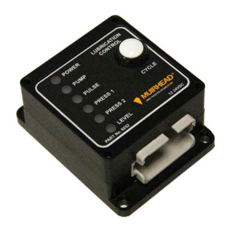
Muirhead 3515 User manual

PRODUCT MANUAL
SPEED ALERT CONTROLLER 8-35 Vdc
Part No. 3515 | 3508

2| 16
M0404.docx | Rev 1.8 | Modified on 26/09/2018 | © Remote Control Technologies Pty Ltd
DISCLAIMER
© Remote Control Technologies Pty Ltd.
■No part of this manual may be reproduced, copied, translated, or transmitted in any form or by any means without the written
permission of RCT.
■Information provided in this manual is intended to be accurate and reliable. However, RCT assumes no responsibility for its use or
infringements upon the rights of third parties that may result from its use.
■All examples and diagrams shown in this manual are intended only as an aid to understanding the text, not to guarantee operation.
RCT will accept no responsibility for actual use of the product based on these illustrative examples.
■Please contact your nearest RCT branch for more information concerning applications in life critical situations or high reliability.
■RCT reserves the right to make changes to any product herein to improve reliability, function or design. All specifications are subject
to change without notice.

M0404.docx | Rev 1.8 | Modified on 26/09/2018 | © Remote Control Technologies Pty Ltd
3| 16
Contents
General Safety Warnings 5
Personal Safety 5
Machine 5
Product 5
Product Overview 6
Features and Functions 6
Operation and Use 7
Installation Guide 7
Wiring Connections 7
Internal Wiring Diagram to suit Toyota/Nissan Application (222l) 8
System Layout Diagram to suit Forklift Application (490j) 9
Calibration 10
3515 Speed Alert Control Unit –Setup Procedure 10
Service Information 12
Service Schedule 12
Service Procedure 12
Parts List 12
Parts Included with the 3515 Speed Alert Controller 12
Parts Included with the 3508 Industrial Speed Alert Kit 12
Compliance and Standards 12
Troubleshooting 13
Technical Specifications 13
Glossary 14
Warranty 14
Revision History 15

4| 16
M0404.docx | Rev 1.8 | Modified on 26/09/2018 | © Remote Control Technologies Pty Ltd
Table of Figures
Figure 1 Muirhead®Speed Alert Controller, part number 3515........................................................................ 6
Figure 1 Drawing 222l –Internal wiring diagram............................................................................................... 8
Figure 2 Drawing 490j –System layout diagram............................................................................................... 9

M0404.docx | Rev 1.8 | Modified on 26/09/2018 | © Remote Control Technologies Pty Ltd
5| 16
General Safety Warnings
Personal Safety
■Everyone is responsible for safety.
■The installer/service personnel should be trained and authorized to complete the required work.
■Ensure that the machine is safely isolated during installation and testing to protect all personnel.
■Complete all required risk assessments and job safety analysis (JSA) before commencing work.
■Observe all site-specific and machine OEM procedures regarding the following:
–working at heights
–working in heat
–working in confined spaces
–all other site-specific occupational health and safety (OH&S) procedures
Machine
■Carry out all prestart operations as per site and machine OEM procedures.
■Ensure the machine is safely isolated during installation and testing to protect the machine and other
equipment in the area.
■Do not operate any machine with a known fault and report all findings to the supervisor in writing.
■Test and operate machine as per machine OEM and site procedures.
■Read and understand machine and site-specific operational and testing instructions.
Product
Before applying power to the equipment, the user/repairer/ installer must read all product instructions. If in
doubt, seek assistance.
■Ensure electrical connections are made as per RCT’s recommendations. Test circuits prior to connecting
power to any component.
■The equipment contains no user serviceable parts inside. Return the unit to RCT for repairs.
■Retain product and installation instructions for future use.
■Ensure that RCT’s recommended service procedures are included in the machine’s service routine.
■Observe all machine, site and RCT product warnings.
■Follow all machine, site and RCT product operating procedures at all time.
The application of safety should not be limited to the above recommendations.

6| 16
M0404.docx | Rev 1.8 | Modified on 26/09/2018 | © Remote Control Technologies Pty Ltd
Product Overview
Figure 1 Muirhead®Speed Alert Controller, part number 3515
The Muirhead®Speed Alert Controller, part number 3515, is designed to warn the operator of excess speeds
determined by two preset values that are fully programmable. The first value activates the warning signal via
relay 1 (RLY 1) while the second value activates the alarm signal via relay 2 (RLY 2). In both warning and
alarm states, devices such as strobe lights and audible alarms can be activated.
The speed alert system is designed to suit all types of forklifts.
Features and Functions
■Compact and robust design
■Increases workplace and road safety
■Reduces speed related injuries
■Reduces fuel, running and maintenance costs
■Extends vehicle service life
■Maintenance and trouble free speed limiting
■Secure speed programming
■Audio warning indication

M0404.docx | Rev 1.8 | Modified on 26/09/2018 | © Remote Control Technologies Pty Ltd
7| 16
Operation and Use
The system detects the speed of the vehicle via a proximity pickup sensor located in the drive train.
If the vehicle’s speed exceeds the first preset level, an audible alarm will sound.
If the driver allows the vehicles speed to exceed the second preset limit, the alarm will continue to sound and
additional warning devices will be activated. Additional warning equipment can include strobe lights or flashing
indicators.
When the vehicle’s speed is reduced and is below the first pre-set limit, the warning alarms will reset and the
speed alert system will return to normal status.
Installation Guide
1. Install the control unit in a suitable location, preferably within the instrument panel area of the forklift.
2. Run the wiring in the most suitable way to keep the wiring harness protected and out of the way of moving
parts.
3. Refer to the wiring tables below and the wiring diagrams on the following pages as a guide on how to wire
up the control unit and the wiring loom.
Note
If ordering a 3515 control unit to replace the module from the 8867 road speed limiter kit, you need to refer to
the 8867 product manual.
Wiring Connections
No.
Colour
Description
1
Red
Ignition 8–30 Vdc
2
Black
Ground
3
White
Speed signal input
4
Orange
Relay 2 warning N/C (optional)
5
Green
Relay 2 warning N/O
6
Pink
Relay 1 warning N/C (optional)
7
Green/Yellow
Relay 1 warning N/O
8
Blue
Test/program

8| 16
M0404.docx | Rev 1.8 | Modified on 26/09/2018 | © Remote Control Technologies Pty Ltd
Internal Wiring Diagram to suit Toyota/Nissan Application (222l)
Figure 2 Drawing 222l –Internal wiring diagram
0
F
E
D
C
B
A
9
8
7
6
5
4
3
2
1
BU
WH
BK
GN/YL
PK
OR
GN
RD
3
2
1
8
7
6
4
5
Rly 2
Rly 1
STATUS
FDU002-P
HEX SW
PUSH
BUTTON
DEUTSCH
(1984)
12345678910 11 12
B
A
C
D
E
F
G
H
B
A
C
D
E
F
G
H
12345678910 11 12
A4
COPYRIGHT - ALL RIGHTS RESERVED
This drawing is the property of REMOTE
CONTROL TECHNOLOGIES PTY LTD (RCT),
and is not to be copied or used in whole or in
part for any purpose without the express
authority of RCT. The drawing is to be returned
to RCT, on demand.
INDUSTRIAL SPEED
ALERT CONTROLLER
INTERNAL WIRING
www.rct.net.au
UNCONTROLLED DOCUMENT
REV
4
DWG No 222l
STATUS
NTS
SCALE
Released
SHEET 1 of 1
BY PD
DRN GT DATE 18/07/05
APPD PD DATE 18/07/05
STOCK
CODE MH-SA-C-M/V
PART
NO 3515
3rd ANGLE
PROJECTION
ALL DIMENSIONS IN MILLIMETERS
REV ZONE DESCRIPTION BY DATE
1added calibration
procedure PD 15/09/05
2push button and text
added BT 17/08/07
3removed calibration text BS 10/02/09
4 C-E9 changed plug to Deutsch BS 03/04/09
WIRING CONNECTIONS
PIN WIRE COLOUR FUNCTION
1RD RED IGNITION 8-30VDC
2BK BLACK GROUND
3WH WHITE SPEED SIGNAL INPUT
4OR ORANGE RELAY 2 WARNING N/C (OPTIONAL)
5GN GREEN RELAY 2 WARNING N/O
6PK PINK RELAY 1 WARNING N/C (OPTIONAL)
7GN/YL GREEN/YELLOW RELAY 1 WARNING N/O
8BU BLUE TEST / PROGRAM

M0404.docx | Rev 1.8 | Modified on 26/09/2018 | © Remote Control Technologies Pty Ltd
9| 16
System Layout Diagram to suit Forklift Application (490j)
Figure 3 Drawing 490j –System layout diagram
RD-FVT
BK-FVT
WH-FVT
GN-FVT
GN/YL-FVT
BU-FVT
OR
BK
SPEED
SENSOR
WH
GN/YL
BK
OVERSPEED
ALARM OUTPUT
GN
PRE-ALARM
LED INDICATOR
BK
IGNITION
12/24 VOLT
BU
TEST/PROGRAM
BK
BK
BK
OR
RD
BK
0
F
E
D
C
B
A
9
8
7
6
5
4
3
2
1
Rly 2
Rly 1
STATUS
FDU002-P
HEX SW
PUSH
BUTTON
1
2
3
4
5
6
7
8
IGNITION
GND
SPEED SIGNAL
PRE-ALARM
OVERSPEED
TEST / PROGRAM
(3515)
(3510)
GND
SIGNAL
GND
IGN
A
B
C
OR
BK
WH
RD
BK
PK
WH
SIGNAL
AMPLIFIER
(4804)
CONNECT TO
SPEED SIGNAL
* OPTIONAL: IF REQUIRED CONNECT THE
SIGNAL AMPLIFIER AS SHOWN
12345678910 11 12
B
A
C
D
E
F
G
H
B
A
C
D
E
F
G
H
12345678910 11 12
A4
COPYRIGHT - ALL RIGHTS RESERVED
This drawing is the property of REMOTE
CONTROL TECHNOLOGIES PTY LTD (RCT),
and is not to be copied or used in whole or in
part for any purpose without the express
authority of RCT. The drawing is to be returned
to RCT, on demand.
INDUSTRIAL SPEED
ALERT TO SUIT
FORKLIFT
SYSTEM LAYOUT
www.rct.net.au
UNCONTROLLED DOCUMENT
REV
0
DWG No 490j
STATUS
NTS
SCALE
Released
SHEET 1 of 1
BY MT
DRN CW DATE 02/10/13
APPD MT DATE 02/10/13
STOCK
CODE ----
PART
NO ----
3rd ANGLE
PROJECTION
ALL DIMENSIONS IN MILLIMETERS
WIRE LEGEND
BK - BLACK PK - PINK
BU - BLUE PU - PURPLE
BN - BROWN RD -RED
GN - GREEN WH - WHITE
GY - GREY YL - YELLOW
OR - ORANGE TQ - TURQUOISE
REV ZONE DESCRIPTION BY DATE

10 | 16
M0404.docx | Rev 1.8 | Modified on 26/09/2018 | © Remote Control Technologies Pty Ltd
Calibration
3515 Speed Alert Control Unit –Setup Procedure
If the installed location of the speed alert control unit has made the on-board push button inaccessible, the
blue wire can be used as a substitute. In this case, replace the statement ‘press the push button’ with ‘bridge
the blue wire to earth (0 V)’ in all instances in the following instructions. Also replace the statement ‘while the
button is pressed’ with ‘while the blue wire is bridged to earth’.
When in programming/setting mode as shown below, all frequency settings are half the actual required value.
As an example if 18 km/h (750 Hz) is required then the trip frequency should be set to 9 km/h (375 Hz). When
the power is cycled at the completion of programming, the trip frequency will be 18 km/h (750 Hz).
Note
To set the trip frequency and release points for relays 1 and 2, the program code 012 must be entered.
To enter program code 012:
1. Select 0on the HEX rotary switch and press the push button for one second, this will be acknowledged by
the status LED staying on while the button is pressed
2. Select 1on the HEX rotary switch and press the push button for one second, this will be acknowledged by
the status LED staying on while the button is pressed
3. Select 2on the HEX rotary switch and press the push button for one second, this will be acknowledged by
the status LED staying on while the button is pressed
When the program code 012 has been entered, the status indicator will start flashing every six seconds.
If the indicator does not flash every six seconds, cycle the power to the unit and repeat steps 1 to 3.
Setting the trip and release frequencies (note that relay 1 is usually for pre-alarm if both relays are
being utilised):
1. Select 1on the HEX rotary switch to select relay 1 trip frequency. Drive the machine to 50% of the desired
pre-alarm speed and set the resulting frequency by pressing the push button for one second. This will be
acknowledged by the status indicator staying on while the button is pressed
2. Select 2on the HEX rotary switch to select relay 2 trip frequency. Drive the machine to 50% of the desired
alarm speed and set the resulting frequency by pressing the push button for one second. This will be
acknowledged by the status indicator staying on while the button is pressed.
3. Select 3on the HEX rotary switch to select relay 1 release frequency. Drive the machine to 50% of the
desired pre-alarm release speed and set the resulting frequency by pressing the push button for one
second. This will be acknowledged by the status indicator staying on while the button is pressed
4. Select 4on the HEX rotary switch to select relay 2 release frequency. Drive the machine to 50% of the
desired alarm release speed and set the resulting frequency by pressing the push button for one second.
This will be acknowledged by the status indicator staying on while the button is pressed
5. Cycle the power by turning the unit off and then back on to save the settings. The unit is now set and ready
for a test run to confirm the new values
Important
If tampering has occurred and the 3515 control unit is not functioning correctly, then a factory restore may be
required. To do this, program code 06C must to be entered.
To enter program code 06C:
1. Select 0on the HEX rotary switch and press the push button for one second, this will be acknowledged by
the status indicator staying on while the button is pressed
2. Select 6on the HEX rotary switch and press the push button for one second, this will be acknowledged by
the status indicator staying on while the button is pressed
3. Select Con the HEX rotary switch and press the push button for one second, this will be acknowledged
by the status indicator staying on while the button is pressed
When the program code 06C has been entered, the status indicator will start flashing continuously. If this
is not occurring, cycle the power to the unit and repeat from step 1 (restore factory setting above).
4. Restore to factory settings by selecting 8on the HEX rotary switch, then press the push button for one
second. This will be acknowledged by the status indicator staying on while the button is pressed.
5. Cycle the power by turning the unit off and then back on to save the settings
6. Repeat the setup procedure as detailed previously.

M0404.docx | Rev 1.8 | Modified on 26/09/2018 | © Remote Control Technologies Pty Ltd
11 | 16
Typical trip and release frequencies for fork lift trucks
These frequencies are set in programming mode and are equal to RCT factory settings.
RLY 1
RLY 2
Trip
336 Hz
420 Hz
Release
252 Hz
336 Hz
Note
RCT configures these frequencies as a standard setup. Also note that if a factory restore of 06C8 is initiated,
then the set ups as listed above will be installed and all other settings will be erased or lost.

12 | 16
M0404.docx | Rev 1.8 | Modified on 26/09/2018 | © Remote Control Technologies Pty Ltd
Service Information
Service Schedule
The manufacturer recommends that the following service procedure should be performed at each machine’s
scheduled service interval.
Service Procedure
1. Perform a visual inspection; include the following:
a) Control unit.
b) Wiring connections and looms.
c) Check that the speed sensor is in good working condition.
2. Perform a system test. (Refer to the Operation and Use section in this manual for information on how the
controller operates.)
a) For any problems found when testing the controller, refer to the Troubleshooting section further in this
manual.
Parts List
Parts Included with the 3515 Speed Alert Controller
Part No.
Description
Qty
3515
Speed Alert Control Unit
1
Parts Included with the 3508 Industrial Speed Alert Kit
Part No.
Description
Qty
3510
Loom to suit Industrial Speed Alert Kit
1
11109
LED 6-32 Volt Red 2T
1
4040
Strobe Light Blue 4” 12–48 V
1
3515
Speed Alert Control Unit
1
4804
Signal Amplifier (not supplied with the kit, order if necessary for installation of the 3515
control unit)
0
Compliance and Standards
RCT has an obligation as a manufacturer to comply with the regulations as required by the relevant regulatory
bodies, depending on the market and location.
This product currently complies with the following:
ACMA
CISPR 22:2006 Class A procedures –Information technology equipment –Radio disturbance
characteristics –Limits and methods of measurement
EU
EMC Directive 2004/104/EC
RoHS Directive 2011/65/EU
FCC
This device is exempt from FCC regulations under 47 CFR 15.103 Exempted devices
IC
This device is exempt from IC regulations under ICES-003 —Information Technology
Equipment (ITE) —Limits and Methods of Measurement

M0404.docx | Rev 1.8 | Modified on 26/09/2018 | © Remote Control Technologies Pty Ltd
13 | 16
Troubleshooting
Technical Specifications
Dimensions, control unit only:
Length: 65 mm | Width: 37 mm | Height/Depth: 23 mm
Dimensions, boxed for freight:
Length: 300 mm | Width: 200 mm | Height/Depth: 100 mm
Weight, control unit only:
0.19 kg
Weight, including loom and
packaging for freight:
0.20 kg
Input voltage:
12 to 24 Vdc
Operating temperature range:
0 to 70 °C
Connection types:
8-pin Deutsch receptacle
Inputs:
Ignition, earth, speed signal input
Min & max input voltage:
8 to 35 Vdc
Circuit protection:
Reverse polarity protection
Enclosure type:
LCM
Environmental protection IP rating:
IP67
Programming/adjustment:
YES (through the use of the onboard HEX switch)
Frequency input voltage hysteresis:
4 V high, 2 V low
Continuous carrying current:
10 A
Input filter:
Single pole at 100 kHz
Response time (freq > 15 Hz):
Better than 120 ms
Response time (freq < 15 Hz):
Better than 2 cycles
Frequency tolerance (0–50 °C):
± 0.5%
Detect jitter:
Less than 0.25%
Adjustable trip frequency:
Yes (0.01 Hz to 25 kHz)
Adjustable release frequency:
Yes (0.01 Hz to 25 kHz) –will force 1% lower than trip frequency
Fault
Remedy
Relay outputs do not activate at desired
speed.
Perform a factory restore 06c8 and reprogram the relay trip
frequencies
Note: Relay trip frequencies in programming mode are half the
desired trip frequency.
The unit will not program or program
instructions do not yield the desired
outcome.
Perform a factory restore 06c8 and reprogram desired
parameters.

14 | 16
M0404.docx | Rev 1.8 | Modified on 26/09/2018 | © Remote Control Technologies Pty Ltd
Glossary
Warranty
Please see the RCT standard warranty, available on our website - www.rct-global.com.
A
Amp (Ampere)
MIN
Minimum
ac
alternating current
mm
millimetres
AMS
Advanced Management System
mW
Milliwatts
Aux
Auxiliary Output
N/A
Not Applicable
CAN
Controller Area Network
N/C
Normally Closed
CMIO
Control Master Input Output PCB
N/O
Normally Open
CMR
Control Master Receiver
OEM
Original Equipment Manufacturer
CMT
Control Master Transmitter
O/P
Outputs
CM2200
Control Master 2200 Remote Set
Out
Output
COMMS
Communications
PB
Push Button
CPU
Central Processor Unit
PC
Personal Computer
dc
direct current
PCB
Printed Circuit Board
E.G.
For example
PIN
Personal Identification Number
ETR
Energised To Run
PLC
Programmable Logic Controller
ETS
Energised To Stop
POT
Potentiometer
ESD
Engine Shutdown
PPM
Pulses Per Metre
FET
Field Effect Transistor
PWM
Pulse Width Modulation
GND
Ground
PWR
Power
H
Hours
Rev
Revision
HEX
Hexadecimal Numbering System
RF
Radio Frequency
ID
Identity
RH
Relative Humidity
i.e
That is
rpm
Revolutions per minute
In
Input
RX
Receiver
IP
Ingress Protection
RS232
Recommended Standard (number 232)
for serial data transfer
kg
Kilogram
Source
The output can supply/drive current out
Km/h
Kilometres Per Hour
SYS
System
LCD
Liquid Crystal Display
TOV
Text On Video
LED
Light Emitting Diode
TX
Transmitter
LK
Link
V
Volts
M
Minutes
°C
Degrees Centigrade
mA
Milliamps
#
Number
MAX
Maximum
<
Less Than
MCU
Multi-Control Unit
>
Greater Than
MFU
Multi-Function Unit
%
Percentage
MHz
Mega Hertz (million(s) cycles per
second)

M0404.docx | Rev 1.8 | Modified on 26/09/2018 | © Remote Control Technologies Pty Ltd
15 | 16
Revision History
Rev
Date
By
Details of change
1.0
04/05/2009
BS
Initial document draft and approval
1.1
20/11/2009
AB
Updated drawing 350t
1.2
01/04/2010
GS
Updated drawing 358v
1.3
24/01/2011
SD
Updated drawing 350t
1.4
09/10/2013
MT
Replaced drawing 192j with 490j
1.5
22/05/2015
JG
Updated drawing 358v
1.6
15/09/2015
CamB
Revised manual and updated to new format
1.7
02/06/2016
JB
Updated Technical Specifications table
Added Compliance and Standards information
1.8
26/09/2018
CC
Updated manual to latest standards Including adding Table of Figures and
Revision History sections)

Discover more: www.rct-global.com
sales@rct-global.com
AUSTRALIA: +61 (0) 8 9353 6577
AFRICA: +27 (0) 83 292 4246
CANADA: +1 705 590 4001
RUSSIA / CIS: +7 (910) 411 11-74
SOUTH AMERICA: +56 9 8731 9925
USA: +1 801 938 9214
This manual suits for next models
1
Table of contents
Other Muirhead Controllers manuals
Popular Controllers manuals by other brands

Mitsubishi Electric
Mitsubishi Electric RJ72GF15-T2 user manual

SMC Networks
SMC Networks THERMO-CON HEC001 Series Communications manual

CWE
CWE GSM-4 instruction manual

Renesas
Renesas TPS-1 user manual

Bosch
Bosch Rexroth IndraControl L45 Project planning manual

meitav-tec
meitav-tec PYROBOX3/19 Installation and operating manual

resideo
resideo Multiple Aquastat L4081A quick start guide

Mitel
Mitel SX-200 Technician's handbook

QSC
QSC SC28 user manual

Ruijie Networks
Ruijie Networks RG-WS6008 Series Hardware installation and reference guide

Jenny Science
Jenny Science XENAX Xvi 75V8S instruction manual

VocoPro
VocoPro DKC-100 PRO user guide