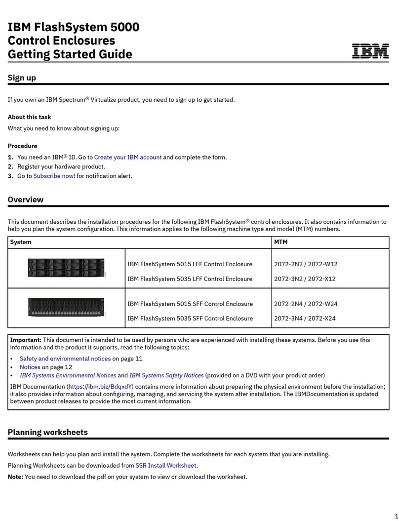
IBM FlashSystem 900 User manual

3746 Nways Multiprotocol Controller
Model 900 ÉÂÔ
Service Guide
SY33-2116-02


3746 Nways Multiprotocol Controller
Model 900 ÉÂÔ
Service Guide
SY33-2116-02

Note!
Before using this information and the product it supports, be sure to read the general information under “Notices”
on page xv.
Third Edition (July 1999)
This edition applies to the 3746 Nways Multiprotocol Controller Model 900.
Order publications through your IBM representative or the IBM branch office serving your locality. Publications are not stocked at the
address given below.
A form for readers’ comments appears at the back of this publication. If the form has been removed, address your comments to:
Department CGFA
Design & Information Development
IBM Corporation
PO Box 12195
Research Triangle Park NC 27709
U.S.A.
When you send information to IBM, you grant IBM a nonexclusive right to use or distribute the information in any way it believes
appropriate without incurring any obligation to you.
Copyright International Business Machines Corporation 1997, 1999. All rights reserved.
US Government Users Restricted Rights – Use, duplication or disclosure restricted by GSA ADP Schedule Contract with IBM Corp.

Contents
Figures . . . . . . . . . . . . . . . . . . . . . . . . . . . . . . . . . . . . . . . . . . ix
Tables . . . . . . . . . . . . . . . . . . . . . . . . . . . . . . . . . . . . . . . . . . xiii
Notices . . . . . . . . . . . . . . . . . . . . . . . . . . . . . . . . . . . . . . . . . xv
Electronic Emission Notices .............................. xvi
Industry Canada Class A Emission Compliance Statement .......... xvi
Avis de conformité aux normes d'Industrie Canada .............. xvi
European Union (EU) Mark of Conformity Statement ............. xvi
Japanese Voluntary Control Council for Interference (VCCI) Statement ... xvii
Korean Communications Statement ....................... xvii
Taiwanese Class A Warning Statement .................... xviii
New Zealand Radiocommunications (Radio) Regulations .......... xviii
Notice to UK Users .................................. xviii
Year 2000 Statement ................................ xviii
Trademarks . . . . . . . . . . . . . . . . . . . . . . . . . . . . . . . . . . . . . . . xix
General and Product Safety Information ..................... xxi
Service Inspection Safety Procedures ...................... xxi
Safety and Disposal Instructions For Batteries ................. xxi
Service Inspection Safety Procedures for the 3745, 3746-900, and Controller
Expansion . . . . . . . . . . . . . . . . . . . . . . . . . . . . . . . . . . . . . . . xxii
Introduction . . . . . . . . . . . . . . . . . . . . . . . . . . . . . . . . . . . . . . xxii
Control Panel LED Status Versus 3746-900 States ............. xxxvi
3745 Model 17A/3746-900 Power Supply CP/CB and Fuse Reference . xxxvii
3745 Models 21A to 61A Power Supply CP/CB Reference ........ xxxviii
Controller Expansion Fuse Reference .................... xxxviii
3745 Models 21A to 61A Primary Power Part Number ........... xxxix
3746-900 Primary Power Part Number ..................... xxxix
Sicherheitsüberprüfungen für IBM 3745, 3746-900 und die Erweiterung der
Steuereinheit . . . . . . . . . . . . . . . . . . . . . . . . . . . . . . . . . . . . . . xl
Einführung . . . . . . . . . . . . . . . . . . . . . . . . . . . . . . . . . . . . . . . xl
Bedeutung der LEDs am Bedienungsfeld der 3746-900 ............ liv
Stromversorgung, Sicherungsautomaten (CB), Überstromschutzschalter (CP)
und Sicherungen (F) der 3745, Modell 17A/3746-900 ............. lv
Stromversorgung, Sicherungsautomaten (CB) und Überstromschutzschalter
(CP) der Modelle 21A bis 61A der 3745 .................... lvi
Sicherungen der Erweiterung der Steuereinheit ................. lvi
Teilenummern der Netzteile der Modelle 21A bis 61A der 3745 ....... lvii
Teilenummern der Netzteile der 3746-900 .................... lvii
Safety Label Locations ................................ lxxvii
Safety Label Locations on the 3745 Models 17A ............... lxxvii
3745 Model 17A Safety Label Identifications ................. lxxix
Safety Label Locations on the 3745 Models 21A to 61A ........... lxxx
3745 Models 21A to 61A Safety Label Identifications ........... lxxxiii
Safety Label Locations on the 3746-900 ................... lxxxiv
Safety Label Location on the LCB ...................... lxxxiv
3746-900 Safety Label Identifications ..................... lxxxv
LCB Safety Label ................................ lxxxvi
Controller Expansion Label Locations .................... lxxxvi
Copyright IBM Corp. 1997, 1999 iii

3745 Model 17A Safety Label Part Numbers by Country ......... lxxxvii
3745 Models 21A to 61A Safety Label Part Numbers by Country .... lxxxviii
3746-900 Safety Label Part Numbers by Country ............. lxxxix
About This Manual .................................. xci
Aim of this manual ................................... xci
Who should read this manual ............................. xci
How this manual is organized ............................ xci
Chapter 1. START . . . . . . . . . . . . . . . . . . . . . . . . . . . . . . . . . . 1-1
START - How to Begin Troubleshooting ...................... 1-1
Console Use for maintenance ........................... 1-1
Finding a Service Procedure ............................ 1-3
CPN or FRU to Exchange ............................. 1-4
Other Symptoms . . . . . . . . . . . . . . . . . . . . . . . . . . . . . . . . . . 1-4
Run Diagnostics . . . . . . . . . . . . . . . . . . . . . . . . . . . . . . . . . . . 1-4
Miscellaneous Informations . . . . . . . . . . . . . . . . . . . . . . . . . . . . 1-6
3745/3746-900/Service Processor Windows Overview .............. 1-7
Service Processor Menu Details ......................... 1-8
3746-9x0 Menu Details .............................. 1-10
Problems During Machine, EC or MES Installation ............... 1-12
Selection Table . . . . . . . . . . . . . . . . . . . . . . . . . . . . . . . . . . 1-12
Symptom Index . . . . . . . . . . . . . . . . . . . . . . . . . . . . . . . . . . . . 1-13
General Verbal Symptoms ............................ 1-13
3746-900 Control Panel Symptoms ....................... 1-14
3746-900 Control Panel Codes ........................... 1-15
Using the MIP FRU Group Table .......................... 1-24
3746-900 FRU Group Table ........................... 1-25
3746-900/Service Processor Maintenance Using a CPN .......... 1-26
3746-900 Maintenance Using an SRC Sequence Number ......... 1-28
3746-900 Maintenance Using a FRU list .................... 1-28
Service Processor Maintenance Using an SRC Sequence Number .... 1-28
3746-900 FRU List .................................. 1-29
MAP: 3746-900 FRU Exchange ........................ 1-34
MAP: CBSA Check LED ON .......................... 1-36
MAP: Ready and Standby LEDs are OFF .................. 1-37
MAP: Standby LED Blinking .......................... 1-40
MAP: Standby LED ON ............................. 1-43
MAP: Ready LED Blinking ........................... 1-49
MAP: Ready LED ON .............................. 1-52
3746-900 FRU list for exchange ........................ 1-55
MAP: ARC . . . . . . . . . . . . . . . . . . . . . . . . . . . . . . . . . . . . . 1-57
MAP: CBSP/CBSP2/CBSP3 . . . . . . . . . . . . . . . . . . . . . . . . . . 1-62
MAP: CLP/CLP3 . . . . . . . . . . . . . . . . . . . . . . . . . . . . . . . . . 1-65
MAP: TIC3 of the CBSP ............................. 1-74
MAP: ESCC/ESCC2/ESCP/ESCP2/ESCP3 . . . . . . . . . . . . . . . . . . 1-76
MAP: TRP/TRP2/TRP3 . . . . . . . . . . . . . . . . . . . . . . . . . . . . . 1-82
MAP: CBC . . . . . . . . . . . . . . . . . . . . . . . . . . . . . . . . . . . . . 1-85
MAP: LCPE . . . . . . . . . . . . . . . . . . . . . . . . . . . . . . . . . . . . 1-90
MAP: LCEE . . . . . . . . . . . . . . . . . . . . . . . . . . . . . . . . . . . . 1-92
MAP: LCPB, LCPE, LCEB, LCEE ....................... 1-94
MAP: LIC11 . . . . . . . . . . . . . . . . . . . . . . . . . . . . . . . . . . . . 1-97
MAP: LIC12 . . . . . . . . . . . . . . . . . . . . . . . . . . . . . . . . . . . 1-103
MAP: LIC16 . . . . . . . . . . . . . . . . . . . . . . . . . . . . . . . . . . . 1-107
iv 3746-900: Service Guide

MAP: TIC3 . . . . . . . . . . . . . . . . . . . . . . . . . . . . . . . . . . . 1-111
MAP: SIE . . . . . . . . . . . . . . . . . . . . . . . . . . . . . . . . . . . . 1-114
MAP: SPD2 . . . . . . . . . . . . . . . . . . . . . . . . . . . . . . . . . . . 1-117
MAP: 3746-900 SPS, Control Panel ..................... 1-121
3746-900 ACPW, DCPW, Transformer .................... 1-123
MAP: 3746-900 in Offline Mode ....................... 1-124
MAP: No Problem Found on All the FRUS with Diagnostics in
Concurrent Mode . . . . . . . . . . . . . . . . . . . . . . . . . . . . . . . 1-130
MAP: 3746-900 Ending Exchange Procedure After Power ON ..... 1-136
MAP: 3746-900 Ending Procedure In Offline Mode ............ 1-137
MAP: 3746-900 Ending Procedure in Concurrent Mode ......... 1-139
MAP: 3746-900 ESCC/ESCC2 Disabling .................. 1-142
MAP: 3746-900 ESCC/ESCC2 Enabling .................. 1-144
MAP: 3746-900 CLP Backup or Standard Mode Setting ......... 1-146
Activate/Deactivate a Resource Via CCM .................. 1-150
3746-900 Setting in Offline Mode ....................... 1-153
Display the FRU List After a Diagnostic Failure ............... 1-154
3746-900 EEPROM Upgrade ........................... 1-155
EEPROM Upgrade Overview ......................... 1-155
EEPROM Upgrade/Downgrade Processing ................. 1-155
Engineering Data Transfer ............................ 1-157
Overview . . . . . . . . . . . . . . . . . . . . . . . . . . . . . . . . . . . . . 1-157
Preparing Engineering Data on the Local Service Processor ....... 1-157
Transferring Engineering Data from the Service Processor ........ 1-158
3746 Model 900 Diagnostic Requirements ................... 1-159
3746-900 Control Panel Use ........................... 1-160
Purpose of the Control Panel ......................... 1-160
Explanation of 3746-900 Panel Keys, LEDs and Switches ........ 1-161
3746-900 Control Panel Display Description ................. 1-162
How to Perform 3746 Model 900 Control Panel Operations ......... 1-163
Power ON . . . . . . . . . . . . . . . . . . . . . . . . . . . . . . . . . . . . 1-163
General IML . . . . . . . . . . . . . . . . . . . . . . . . . . . . . . . . . . . 1-163
CBSA IML . . . . . . . . . . . . . . . . . . . . . . . . . . . . . . . . . . . . 1-163
CBSP Dump . . . . . . . . . . . . . . . . . . . . . . . . . . . . . . . . . . . 1-163
General IML With Diagnostics ......................... 1-163
CBSA IML Without Diagnostics ........................ 1-163
Panel Test . . . . . . . . . . . . . . . . . . . . . . . . . . . . . . . . . . . . 1-163
Service Processor Link Restart ........................ 1-163
Display Error Code ............................... 1-163
Control Panel LED Status Versus 3746-900 States ............ 1-164
IML Request Versus 3746 Model 900 States ................ 1-164
Chapter 2. MAPs for FRU Isolation ........................ 2-1
3746-900 RSF MAP .................................. 2-1
MAP 2000: 3746-900 Manual Call ........................ 2-1
3746-900 Power MAPs ................................ 2-4
MAP 5100: 3746 Model 900 Power Control Subsystem Problems ..... 2-4
MAP 5110: 3746-900 Power ON Problem in Remote Mode ......... 2-8
MAP 5120: 3746-900 Power ON Problem in Local Mode .......... 2-13
MAP 5130: 3746-900 CP1 Tripped. ...................... 2-14
3746-900 -48v DC DISTRIBUTION ....................... 2-16
MAP 5140: 3746-900 CP2 or CP3 Tripped .................. 2-17
MAP 5150: 3746-900 CP4, CP5, CP6, or CP7 Tripped ........... 2-19
MAP 5160: Suspected Problem on 3745/3746-900 Power Connection .. 2-20
Contents v

MAP 5170: Suspected Problem on 3745/3746-900 EPO Cable ...... 2-22
MAP 5180: 3746-900 Ready LED Blinking. .................. 2-23
3746-900/Service Processor/Network Node Processor MAPs ......... 2-25
MAP 2600: 3746-900/Service Processor/Network Node Processor/
Multiaccess Enclosure Link Icons Color Symptom ............. 2-25
MAP 2605: 3746-900 Either CP3, CP4, CP5, CP6, or CP7 is Tripped .. 2-33
MAP 2610: 3746-900 ESCA, LAN, or CLP Problem ............. 2-36
MAP 2615: 3746-900 Configuration Mismatch ................ 2-38
MAP 2620: 3746-900 Control Panel Problem ................ 2-43
MAP 2625: LAN Checking . . . . . . . . . . . . . . . . . . . . . . . . . . . 2-44
MAP 2630: 3746-900 Service Logic Problem ................. 2-45
3746-900 Service Logic Cabling ........................ 2-47
MAP 2635: 3746-900 Several Fans Are in Errors .............. 2-50
MAP 2640: 3746-900 Cable From SPD1 to SPD2 .............. 2-52
MAP 2645: 3746-900 Cable From DCDP to SPD1 ............. 2-54
MAP 2650: 3746-900 Signal Power cable from SPD1 to the Control Panel 2-55
MAP 2655: 3746-900 Cable From SIE to SAC in Multiaccess Enclosure . 2-56
MAP 2660: 3746-900 Intermittent Box Errors ................. 2-58
MAP 2665: 3746-900 Resource Not Present in CDF-E ........... 2-60
MAP 2670: 3746-900 Processor Non-Identified in CDF-E ......... 2-62
MAP 2675: 3746-900 CBC/ESCC/TIC3 Non-Identified in CDF-E ..... 2-64
MAP 2680: 3746-900 LIC11/LIC12/LIC16 Non-Identified in CDF-E .... 2-68
MAP 2685: 3746-900 LCB Non-Identified in CDF-E ............. 2-83
3746-900 ESCA MAPs ............................... 2-88
MAP 2700: 3746-900 Permanent ESCA Problem .............. 2-88
MAP 2710: 3746-900 Any Intermittent ESCA Problem ........... 2-89
MAP 2720: 3746-900 Bit Error Rate Validation ................ 2-90
MAP 2730: 3746-900 ESCA Activation Problem ............... 2-91
3746-900 LAN MAPs ................................ 2-94
MAP 2750: 3746-900 Permanent Service Processor Link Problem .... 2-94
MAP 2760: 3746-900 TRP LAN Problem ................... 2-96
MAP 2770: 3746-900 Duplicate Token Ring Local Address ....... 2-106
3746-900 CLP MAPs ............................... 2-107
MAP 2800: 3746-900 All the Lines of CLP Have a Problem ....... 2-107
MAP 2810: 3746-900 Problem on a Group of ARCs ........... 2-110
MAP 2820: 3746-900 Problem on a LIC11 ................. 2-115
MAP 2830: 3746-900 Problem on a LIC12 ................. 2-127
MAP 2840: 3746-900 Problem on a LIC16 ................. 2-133
MAP 2850: 3746-900 CLP Fallback Problem ................ 2-138
MAP 5550: 3746-900 Activate/Deactivate Line Problems or Line Errors
on CLP . . . . . . . . . . . . . . . . . . . . . . . . . . . . . . . . . . . . . 2-139
MAP 2860: 3746-900 All the Lines of LCBE Have Problem ....... 2-144
Service Processor MAPs ............................. 2-149
MAP 5600: LAN Problem on LAN Attached to the Service Processor . 2-149
MAP 5610: 3746-900/APPN Link Problem ................. 2-154
Chapter 3. How to Run Diagnostics ....................... 3-1
3746-900 Diagnostic Description ........................... 3-1
3746-900 Concurrent Maintenance ........................ 3-14
Concurrent Diagnostics . . . . . . . . . . . . . . . . . . . . . . . . . . . . . . 3-14
Concurrent Repair . . . . . . . . . . . . . . . . . . . . . . . . . . . . . . . . . 3-14
Concurrent Mode Activation Procedure .................... 3-14
How to Run the 3746-900 Control Panel Test .................. 3-15
How to run the 3746-900 Service Processor Link Restart ........... 3-16
vi 3746-900: Service Guide
MAP 6000: How to run 3746-900 Diagnostic in Concurrent Mode ...... 3-17
MAP 6010: How to run 3746-900 Diagnostic in Offline Mode ......... 3-43
MAP 6020: How to Run 3746-900 Specific Diagnostics ............ 3-45
3746-900 Service Logic Cabling ........................ 3-48
MAP 6030: How to Run the Selective IML on the Multiaccess Enclosure .. 3-51
Chapter 4. 3746-900 FRU Exchange ....................... 4-1
Exchange Precautions . . . . . . . . . . . . . . . . . . . . . . . . . . . . . . . . . 4-1
List of 3746-900 FRUs ............................... 4-2
3746-900 FRU Physical Locations .......................... 4-3
3746-900 Basic Board Locations ......................... 4-4
3746-900 Expansion Board Locations ...................... 4-6
3746-900 Front Side Details ............................ 4-8
3746-900 Rear Side Details ............................ 4-9
Exchange an Air Filter .............................. 4-10
Exchange an ACPW ............................... 4-11
Exchange an ARC ................................ 4-13
Exchange a Board ................................ 4-15
Exchange a CBC Cassette ............................ 4-16
Exchange a CBSP/CBSP2/CBSP3 ....................... 4-17
Exchange the Control Panel ........................... 4-19
Exchange a Connectivity Switch ........................ 4-20
Exchange a CSCE ................................ 4-22
Exchange DCDC of Processor ......................... 4-23
Exchange a Connectivity Switch DCDC .................... 4-24
Exchange the Power Distribution DCDP .................... 4-26
Exchange a DCPW ................................ 4-28
Exchange an Enclosure (Basic or Expansion) ................. 4-30
Exchange an ESCC/ESCC2 ........................... 4-32
Exchange a Fan Drawer ............................. 4-33
Exchange a Processor Other than the CBSP (CLP/CLP3,
ESCP/ESCP2/ESCP3 or TRP/TRP2/TRP3) ................. 4-34
Exchange a LCEE ................................. 4-35
Exchange a LCEB ................................. 4-37
Exchange a LCPB ................................. 4-39
Exchange a LCPE ................................. 4-41
Exchange a LIC (Type 11, 12, or 16) ...................... 4-43
Exchange an SIE ................................. 4-45
Exchange an SPD1 ................................ 4-46
Exchange an SPD2 ................................ 4-47
Exchange an SPS ................................. 4-48
Exchange a TIC3 associated With the CBSP ................. 4-49
Exchange a TIC3 ................................. 4-51
Exchange a Transformer ............................. 4-52
CE Leaving Procedure .............................. 4-55
Appendix A. Maintenance Aids . . . . . . . . . . . . . . . . . . . . . . . . . A-1
Special Tools . . . . . . . . . . . . . . . . . . . . . . . . . . . . . . . . . . . . . A-1
General Purpose Tools .............................. A-1
ESD kit . . . . . . . . . . . . . . . . . . . . . . . . . . . . . . . . . . . . . . . A-1
Shipping Group Tools ............................... A-2
Appendix B. 3746-900 Bibliography . . . . . . . . . . . . . . . . . . . . . . B-1
Customer Documentation for the 3745 (All Models), and 3746 (Model 900) . B-1
Contents vii

Additional Customer Documentation for the 3745 Models 130, 150, 160, 170,
and 17A . . . . . . . . . . . . . . . . . . . . . . . . . . . . . . . . . . . . . . . B-6
Service Documentation for the IBM 3745 (Models 210, 21A, 310, 31A, 410,
41A, 610, and 61A) and 3746 (Model 900) ................... B-7
Additional Service Documentation for the IBM 3745 Models 130, 150, 160,
170, and 17A .................................... B-10
Related Signal Converter Products Information ................. B-11
World Wide Web ................................. B-11
Related NCP Service Information ......................... B-12
Glossary . . . . . . . . . . . . . . . . . . . . . . . . . . . . . . . . . . . . . . . X-1
viii 3746-900: Service Guide

Figures
0-1. 3745 Model 17A/3746-900 Power Control Cable Routing ....... xxv
0-2. 3745 Model 21A to 61A/3746-900 UEPO Cable Routing ....... xxvi
0-3. Ground Wire Connection On Controller Expansion .......... xxvii
0-4. Ground Wire Connection Between Attached Controller Expansions xxviii
0-5. Ground Wire Connection Between Controller Expansions at less than
Six Meters . . . . . . . . . . . . . . . . . . . . . . . . . . . . . . . . . xxix
0-6. Ground Wire Connection Between Controller Expansions at more
than Six Meters ............................... xxx
0-7. Ground Pin on Mainline ac/dc Power Cable .............. xxxi
0-8. Ground Pin of the Controller Expansion ac Outlet Distribution Box . xxxi
0-9. LCB Grounding via Screws ........................ xxxii
0-10. LCB Grounding via Ground Wire .................... xxxii
0-11. Ground Wire Connection ......................... xxxiii
0-12. Führung des Stromversorgungskabels bei der 3745 Modell
17A/3746-900 . . . . . . . . . . . . . . . . . . . . . . . . . . . . . . . . xliii
0-13. UEPO-Kabelführung bei der 3745, Modelle 21A bis 61A/3746-900 .. xliv
0-14. Schutzleiteranschluß an der Erweiterung der Steuereinheit ...... xlv
0-15. Schutzleiteranschluß zwischen angeschlossenen Erweiterungen der
Steuereinheit. . . . . . . . . . . . . . . . . . . . . . . . . . . . . . . . . . xlvi
0-16. Schutzleiteranschluß bei einem Abstand von weniger als 6 Metern
zwischen den Erweiterungen der Steuereinheit ............ xlvii
0-17. Schutzleiteranschluß bei einem Abstand über 6 Meter zwischen den
Erweiterungen der Steuereinheit ..................... xlviii
0-18. Schutzleiterkontakt am Hauptstromversorgungskabel .......... xlix
0-19. Schutzleiterkontakt des Wechselstromverteilerkastens der Erweiterung
der Steuereinheit . . . . . . . . . . . . . . . . . . . . . . . . . . . . . . . xlix
0-20. Erdung des Verteilerkastens über Schrauben ............... l
0-21. Erdung des Verteilerkastens über Schutzleiter ............... l
0-22. Schutzleiteranschluß . . . . . . . . . . . . . . . . . . . . . . . . . . . . . li
0-23. 3745 Label and Power Rating Plate Locations (Back) ........ lxxvii
0-24. 3745 Label and Power Rating Plate Locations (Front) ....... lxxviii
0-25. 3745 Model 17A Safety Labels ..................... lxxix
0-26. 3745 (Basic Frame 01) Label and Power Rating Plate Locations .. lxxx
0-27. 3745 (Basic Frame 01) Label and Power Rating Plate Locations
(Detail) . . . . . . . . . . . . . . . . . . . . . . . . . . . . . . . . . . . . lxxx
0-28. 3746-A11 (Frame 02) or 3746-A12 (Frame 03) Label Locations .. lxxxi
0-29. 3746-L13 (Frame 04), 3746-L14 (Frame 05), 3746-L15 (Frame 06)
Label Locations . . . . . . . . . . . . . . . . . . . . . . . . . . . . . . lxxxi
0-30. 3745 Models 21A to 61A Safety Labels ............... lxxxiii
0-31. 3746-900 (Frame 7) Safety Label Location .............. lxxxiv
0-32. LCB Safety Label Location ....................... lxxxiv
0-33. 3745-900 (Frame 07) Safety Labels ................... lxxxv
0-34. LCB Safety Label(PN 80G3928) .................... lxxxvi
0-35. Controller Expansion Label Locations ................. lxxxvi
1-1. Service Processor Configuration Management Functions ....... 1-8
1-2. Service Processor Problem Management Functions .......... 1-8
1-3. Service Processor Operation Management Functions ......... 1-8
1-4. Service Processor Change Management Functions ........... 1-8
1-5. Service Processor Ethernet Bridge Functions .............. 1-9
1-6. Service Processor Performance Management Function ........ 1-9
Copyright IBM Corp. 1997, 1999 ix

1-7. Service Processor PE Functions ...................... 1-9
1-8. 3746-9x0 Configuration Management Functions ............ 1-10
1-9. 3746-9x0 Problem Management Functions ............... 1-10
1-10. 3746-9x0 Operation Management Functions .............. 1-10
1-11. 3746-9x0 Network Node Processor Management Functions ..... 1-11
1-12. 3746-9x0 MAE Management Functions ................. 1-11
1-13. 3746-9x0 Change Management Functions ............... 1-11
1-14. 3746-9x0 Performance Management Function ............. 1-11
1-15. 3746-9x0 PE Functions .......................... 1-11
1-16. Manage Engineering Data Window .................. 1-157
1-17. 3746 Model 900 Control Panel Layout ................ 1-160
2-1. TB1 and TB2 Location on Transformer .................. 2-4
2-2. DCDP and Power Boxes .......................... 2-5
2-3. 3745/3746-900 Remote Powering Possibilities ............. 2-8
2-4. RPO Location 07R-A1 .......................... 2-10
2-5. -48 Volts DC Distribution ......................... 2-16
2-6. CP2 Circuit . . . . . . . . . . . . . . . . . . . . . . . . . . . . . . . . . 2-18
2-7. Test 1 pin assignment ........................... 2-20
2-8. Stand Alone Service Bus (SASB) Routing with Basic Board Only . 2-47
2-9. Stand Alone Service Bus (SASB) Routing with Expansion Board .. 2-48
2-10. Stand Alone Service Bus (SASB) Routing Two Expansion Boards . 2-49
2-11. 3746 Model 9x0 TRP LAN ........................ 2-96
2-12. LAN attached to the Service Processor ................ 2-149
2-13. LAN attached to the Service Processor ................ 2-154
3-1. Parts of 3746-900 Tested by IML With Diagnostics or Whole
3746-900 Offline Diagnostics ........................ 3-7
3-2. Parts of 3746-900 Tested by CLP SATs ................. 3-8
3-3. Parts of 3746-900 Tested by LIC11 MAT ................. 3-8
3-4. Parts of 3746-900 Tested by LIC12 SAT ................. 3-9
3-5. Parts of 3746-900 Tested by LIC12 MAT ................. 3-9
3-6. Parts of 3746-900 Tested by LIC16 SAT ................. 3-9
3-7. Parts of 3746-900 Tested by LIC16 MAT ................. 3-9
3-8. Parts of 3746-900 Tested by LCBB SAT1 ............... 3-10
3-9. Parts of 3746-900 Tested by LCBB SAT2 ............... 3-10
3-10. Parts of 3746-900 Tested by ARC SAT and ARC MAT ....... 3-11
3-11. Parts of 3746-900 and MAE Tested by MAE Selective IML ..... 3-12
3-12. Stand Alone Service Bus (SASB) Routing with Basic Board Only . 3-48
3-13. Stand Alone Service Bus (SASB) Routing with one Expansion Board 3-49
3-14. Stand Alone Service Bus (SASB) Routing with two Expansion
Boards . . . . . . . . . . . . . . . . . . . . . . . . . . . . . . . . . . . . 3-50
4-1. 3746 Model 900 ............................... 4-3
4-2. 3746 Model 900 ............................... 4-3
4-3. Basic Board O7G-A1 Locations (Processor side) ............ 4-4
4-4. Basic Board O7N-A1 Locations (Coupler side) ............. 4-4
4-5. Basic board component location ...................... 4-5
4-6. Expansion Board 07D-A1 or O7E-A1 Locations (Processor side) ... 4-6
4-7. Expansion Board 07L-A1 or O7M-A1 Locations (Coupler side) .... 4-6
4-8. Expansion Board Component Location .................. 4-7
4-9. 3746-900 Front Side ............................. 4-8
4-10. 3746-900 Rear Side ............................. 4-9
4-11. 3746-900 Air Filter Replacement .................... 4-10
4-12. Rear of the 3746-900 ........................... 4-12
4-13. ARC Assembly Identification ....................... 4-13
4-14. 3746 Model 900 CBC Cover ....................... 4-16
x3746-900: Service Guide

4-15. 3746 Model 900 CBC Cassette ..................... 4-16
4-16. 3746 Model 9x0 CBSP Cassette .................... 4-18
4-17. 3746-900 Control Panel Cards ...................... 4-19
4-18. 3746-900 Connectivity Switch ...................... 4-21
4-19. 3746-900 CSCE Cable Connection to the Connectivity Switch (CS) 4-22
4-20. 3746-900 Processor DC/DC ....................... 4-23
4-21. 3746-900 Connectivity Switch and DCDC ............... 4-25
4-22. 3746-900 Power Distribution Box DCDP Front and Rear View ... 4-27
4-23. 3746-900, Rear of DC Power Box .................... 4-29
4-24. 3746-900 Enclosure Installation ..................... 4-31
4-25. 3746-900 ESCC Coupler ......................... 4-32
4-26. 3746-900 Cooling Units .......................... 4-33
4-27. 3746-900 Fan Drawers Location ..................... 4-33
4-28. 3746-900 Cassette Processor ...................... 4-34
4-29. Line Connection Enclosure Base (LCEB) and Line Connection
Enclosure Expansion (LCEE) ...................... 4-35
4-30. LCPE into the LCEE ............................ 4-36
4-31. Line Connection Enclosure Base (LCEB) and Line Connection
Enclosure Expansion (LCEE) ...................... 4-37
4-32. LCPB into the LCEB ............................ 4-38
4-33. Line Connection Enclosure Base (LCEB) and Line Connection
Enclosure Expansion (LCEE) ...................... 4-39
4-34. LCPB into the LCEB ............................ 4-40
4-35. Line Connection Enclosure Base (LCEB) and Line Connection
Enclosure Expansion (LCEE) ...................... 4-41
4-36. LCPE into the LCEE ............................ 4-42
4-37. 3746-900 LIC11 Coupler ......................... 4-43
4-38. 3746-900 LIC12 Coupler ......................... 4-43
4-39. 3746-900 LIC16 Coupler ......................... 4-44
4-40. 3746-900 SIE Cassette .......................... 4-45
4-41. 3746-900 SPD1 Cassette ......................... 4-46
4-42. 3746-900 SPD2 Cassette ......................... 4-47
4-43. 3746-900 TIC3 Coupler .......................... 4-51
4-44. 3746-900 Transformers . . . . . . . . . . . . . . . . . . . . . . . . . . 4-53
4-45. 3746-900 Transformer Handling ..................... 4-54
Figures xi

xii 3746-900: Service Guide

Tables
0-1. Part Numbers . . . . . . . . . . . . . . . . . . . . . . . . . . . . . . . . xxxiv
0-2. ac Input Adjustment ............................ xxxv
0-3. LED Status Versus 3746-900 States .................. xxxvi
0-4. 3745 Model 17A/3746-900 Power Supply CP/CB and Fuse
Reference . . . . . . . . . . . . . . . . . . . . . . . . . . . . . . . . . xxxvii
0-5. 3745 Models 21A to 61A/3746-900 Power Supply CP/CB
Reference . . . . . . . . . . . . . . . . . . . . . . . . . . . . . . . . . xxxviii
0-6. Part Numbers . . . . . . . . . . . . . . . . . . . . . . . . . . . . . . . . xxxix
0-7. Part Numbers . . . . . . . . . . . . . . . . . . . . . . . . . . . . . . . . xxxix
0-8. Teilenummern . . . . . . . . . . . . . . . . . . . . . . . . . . . . . . . . . lii
0-9. Einstellung der Spannung des Wechselstromeingangs ......... liii
0-10. Bedeutung der LEDs am Bedienungsfeld der 3746-900 ........ liv
0-11. Stromversorgung, Sicherungsautomaten (CB), Überstromschutzschalter
(CP) und Sicherungen (F) der 3745, Modell 17A/3746-900 ....... lv
0-12. Stromversorgung, Sicherungsautomaten (CB) und
Überstromschutzschalter (CP) der 3745, Modelle 21A bis
61A/3746-900 . . . . . . . . . . . . . . . . . . . . . . . . . . . . . . . . lvi
0-13. Teilenummern . . . . . . . . . . . . . . . . . . . . . . . . . . . . . . . . lvii
0-14. Teilenummern . . . . . . . . . . . . . . . . . . . . . . . . . . . . . . . . lvii
0-15. Safety Label Numbers by Country ................... lxxxvii
0-16. Safety Label Numbers by Country for 3745 Models 21A to 61A . lxxxviii
0-17. 3746-900 Safety Label Numbers by Country ............. lxxxix
1-1. General Symptoms . . . . . . . . . . . . . . . . . . . . . . . . . . . . 1-13
1-2. Control Panel Symptoms ......................... 1-14
1-3. 3746 Model 900 Control Panel Code .................. 1-15
1-4. 3746 Model 900 FRU Group ....................... 1-25
1-5. Panel Display Values .......................... 1-162
1-6. LED Status Versus 3746-900 States ................. 1-164
1-7. IML Request Versus 3746-900 States ................ 1-164
2-1. Icons Color Selection Table ....................... 2-26
3-1. 3746-900 Diagnostics Available ...................... 3-2
B-1. Customer Documentation for the 3745 Models X10 and X1A, and
3746 Model 900 .............................. B-1
B-2. Additional Customer Documentation for the 3745 Models 130 to 17A B-6
B-3. Service Documentation for the 3745 Models x10 and x1A, and 3746
Model 900 . . . . . . . . . . . . . . . . . . . . . . . . . . . . . . . . . . B-7
B-4. Additional Service Documentation for the 3745 Models 1x0 and 17A B-10
Copyright IBM Corp. 1997, 1999 xiii

xiv 3746-900: Service Guide

Notices
References in this publication to IBM products, programs, or services do not imply
that IBM intends to make these available in all countries in which IBM operates.
Any reference to an IBM product, program, or service is not intended to state or
imply that only IBM’s product, program, or service may be used. Any functionally
equivalent product, program, or service that does not infringe any of IBM’s intellec-
tual property rights may be used instead of the IBM product, program, or service.
Evaluation and verification of operation in conjunction with other products, except
those expressly designated by IBM, are the user’s responsibility.
IBM may have patents or pending patent applications covering subject matter in
this document. The furnishing of this document does not give you any license to
these patents. You can send license inquiries, in writing, to:
IBM Director of Licensing
IBM Corporation
North Castle Drive
Armonk, NY 10504-1785
U.S.A.
For license inquiries regarding double-byte (DBCS) information, contact the IBM
Intellectual Property Department in your country or send inquiries, in writing, to:
IBM World Trade Asia Corporation
Licensing
2-31 Roppongi 3-chome, Minato-ku
Tokyo 106, Japan
The following paragraph does not apply to the United Kingdom or any other country
where such provisions are inconsistent with local law:
INTERNATIONAL BUSINESS MACHINES CORPORATION PROVIDES THIS PUB-
LICATION "AS IS" WITHOUT WARRANTY OF ANY KIND, EITHER EXPRESS OR
IMPLIED, INCLUDING, BUT NOT LIMITED TO, THE IMPLIED WARRANTIES OF
NON-INFRINGEMENT, MERCHANTABILITY OR FITNESS FOR A PARTICULAR
PURPOSE. Some states do not allow disclaimer of express or implied warranties
in certain transactions, therefore, this statement may not apply to you.
This information could include technical inaccuracies or typographical errors.
Changes are periodically made to the information herein; these changes will be
incorporated in new editions of the publication. IBM may make improvements
and/or changes in the product(s) and/or the program(s) described in this publication
at any time without notice.
This information is for planning purposes only. The information herein is subject to
change before the products described become available.
Copyright IBM Corp. 1997, 1999 xv

Electronic Emission Notices
Federal Communications Commission (FCC) Statement
Note: This equipment has been tested and found to comply with the limits for a
Class A digital device, pursuant to Part 15 of the FCC Rules. These limits are
designed to provide reasonable protection against harmful interference when the
equipment is operated in a commercial environment. This equipment generates,
uses, and can radiate radio frequency energy and, if not installed and used in
accordance with the instruction manual, may cause harmful interference to radio
communications. Operation of this equipment in a residential area is likely to cause
harmful interference, in which case the user will be required to correct the interfer-
ence at his own expense.
Properly shielded and grounded cables and connectors must be used in order to
meet FCC emission limits. IBM is not responsible for any radio or television inter-
ference caused by using other than recommended cables and connectors or by
unauthorized changes or modifications to this equipment. Unauthorized changes or
modifications could void the user's authority to operate the equipment.
This device complies with Part 15 of the FCC Rules. Operation is subject to the
following two conditions: (1) this device may not cause harmful interference, and
(2) this device must accept any interference received, including interference that
may cause undesired operation.
Industry Canada Class A Emission Compliance Statement
This Class A digital apparatus complies with Canadian ICES-003.
Avis de conformité aux normes d'Industrie Canada
Cet appareil numérique de la classe A est conforme à la norme NMB-003 du
Canada.
European Union (EU) Mark of Conformity Statement
This product is in conformity with the protection requirements of EU Council Direc-
tive 89/336/EEC on the approximation of the laws of the Member States relating to
electromagnetic compatibility. IBM cannot accept responsibility for any failure to
satisfy the protection requirements resulting from a non-recommended modification
of the product, including the fitting of non-IBM option cards.
This product has been tested and found to comply with the limits for Class A Infor-
mation Technology Equipment according to CISPR 22/European Standard EN
55022. The limits for Class A equipment were derived for commercial and indus-
trial environments to provide reasonable protection against interference with
licensed communication equipment.
Attention: This is a Class A product. In a domestic environment this product may
cause radio interference in which case the user may be required to take adequate
measures.
Zulassungsbescheinigung laut dem Deutschen Gesetz über die
elektromagnetische Verträglichkeit von Geräten (EMVG) vom 30. August 1995
(bzw. der EMC EG Richlinie 89/336).
xvi 3746-900: Service Guide
Dieses Gerät ist berechtigt, in Übereinstimmung mit dem Deutschen EMVG das
EG-Konformitätszeichen - CE - zu führen.
Verantwortlich für die Konformitätserklärung nach Paragraph 5 des EMVG ist die
IBM Deutschland Informationssysteme GmbH, 70548 Stuttgart.
Informationen in Hinsicht EMVG Paragraph 3 Abs. (2) 2:
EN 55022 Klasse A Geräte müssen mit folgendem Warnhinweis versehen werden:
“Warnung: Dies ist eine Einrichtung der Klasse A. Diese Einrichtung kann im
Wohnbereich Funkstörungen verursachen; in diesem Fall kann vom Betreiber
verlangt werden, angemessene Maßnahmen durchzuführen und dafür
aufzukommen.”
EN 50082-1 Hinweis:
“Wird dieses Gerät in einer industriellen Umgebung betrieben (wie in EN 50082-2
festgelegt), dann kann es dabei eventuell gestört werden. In solch einem Fall ist
der Abstand bzw. die Abschirmung zu der industriellen Störquelle zu vergrößern.”
Anmerkung:
Um die Einhaltung des EMVG sicherzustellen, sind die Geräte, wie in den IBM
Handbüchern angegeben, zu installieren und zu betreiben.
Das Gerät erfüllt die Schutzanforderungen nach EN 50082-1 und EN 55022 Klasse A.
Japanese Voluntary Control Council for Interference (VCCI) Statement
This product is a Class A Information Technology Equipment and conforms to the
standards set by the Voluntary Control Council for Interference by Technology
Equipment (VCCI). In a domestic environment this product may cause radio inter-
ference in which case the user may be required to take adequate measures.
Korean Communications Statement
Please note that this device has been certified for business purpose with regard to
electromagnetic interference. If you find this is not suitable for your use, you may
exchange it for one of residential use.
Notices xvii

Taiwanese Class A Warning Statement
New Zealand Radiocommunications (Radio) Regulations
Attention: This is a Class A product. In a domestic environment this product may
cause radio interference in which case the user may be required to take adequate
measures.
Notice to UK Users
The IBM 3746 Model 900 and IBM 3746 Model 950 are manufactured according to
the International Safety Standard IEC950 and, as such, are approved in the UK
under the General Approval number NS/G/1234/J/100003.
The Active Remote Couplers (ARCs) and the X.21 Interface, housed within the
3746 Model 900 and 3746 Model 950, are approved separately, each having their
own independent approval number. These interface adapters, supplied by IBM, do
not contain excessive voltages. An excessive voltage is one which exceeds 42.4 V
peak ac or 60 V dc. They interface with the 3746 Model 900 or 3746 Model 950,
using Safe Extra Low Voltages only.
In order to maintain the independent approval of the IBM adapters, it is essential
that other optional cards, not supplied by IBM, do not use mains voltages or any
other excessive voltages. Seek advice from a competent engineer before installing
other adapters not supplied by IBM.
Year 2000 Statement
This product is Year 2000 ready. When used in accordance with its associated
documentation, it is capable of correctly processing, providing, and/or receiving
date data within and between the 20th and 21st centuries, provided all other pro-
ducts (for example, software, hardware, and firmware) used with the product prop-
erly exchange accurate date data with it.
For more information, refer to:
http://www.ibm.com/year2000
xviii 3746-900: Service Guide
Other manuals for FlashSystem 900
2
Other IBM Controllers manuals

IBM
IBM SAS RAID Series User manual

IBM
IBM 3745 21A User manual

IBM
IBM 3174 User manual

IBM
IBM 3720 Quick setup guide

IBM
IBM 3174 Reference manual

IBM
IBM FlashSystem 900 Instruction Manual

IBM
IBM ServeRAID-4 Ultra160 Series Service manual

IBM
IBM 3745-130 User manual

IBM
IBM ServeRAID Service manual

IBM
IBM ServeRAID-MR10is User manual

IBM
IBM 3745 130 Setup guide

IBM
IBM 3708 Technical manual

IBM
IBM ServeRAID-4 Ultra160 Series User manual

IBM
IBM 3745 Series Owner's manual

IBM
IBM 3745 Series Parts list manual

IBM
IBM ServeRAID M1215 SAS User manual

IBM
IBM 3745 Series Parts list manual

IBM
IBM Redbooks ServeRAID-MR10i User manual

IBM
IBM 950 User manual

IBM
IBM ThinkPad 130 Reference manual