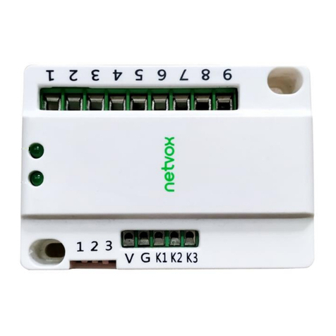
netvox ZigBee Z831 User manual

ZigBeeTM- Multifunctional Wireless Control Box
User Manual
Multifunctional Wireless Control Box
Model: Z831
20150907
For firmware V0.0.0.25 and later

Model: Z831
1
Table of Contents
1. Introduction........................................................................................................................................2
2. Product Appearance........................................................................................................................... 2
3. Specification...................................................................................................................................... 3
4-1. Connection...............................................................................................................................4
(A) Operation mode 1 (High power motor mode)................................................................... 4
(B) Operation mode 2 (Low power motor mode)....................................................................5
(C) Operation mode 3 (Relay output mode)............................................................................ 5
4-2. Join Zigbee network................................................................................................................ 5
4-3. Permit join............................................................................................................................... 6
4-4. Binding.................................................................................................................................... 6
4-5. Working procedure on individual mode.................................................................................. 6
(A) Operation mode 1 (High power motor mode)................................................................... 6
(B) Operation mode 2 (Low power motor mode)....................................................................6
(C) Operation mode 3 (Relay output mode)............................................................................ 7
4-6. Factory Setting.........................................................................................................................7
4-7. Access to working modes........................................................................................................ 7
4-8. Select working modes..............................................................................................................7
4-9. Zigbee cluster for Z831........................................................................................................... 8
(1) Working mode 1 & 2 cluster.............................................................................................. 8
(2) Working mode 3 (Relay output mode) cluster................................................................... 9
5. Devices to work with Z831..............................................................................................................10
6. Related Netvox Device.................................................................................................................... 11
7. Important Maintenance Instruction..................................................................................................11

Model: Z831
2
1. Introduction
Z831 as a wireless switch device based on ZigBee protocol, it can communicates with routers,
coordinator, and end devices in the network. There are 3 relay output modules with each device type
allowing users to remote control the switch. Z831 is also a router device which permits other devices
to join the network.
2. Product Appearance
Port 4
Port 3
Port 2
Port 1
Status Indicator
Network Indicator
Mode Switch 2
Mode Switch 1
1
Mode Switch 3
Switch 1
Port 5
Port 6
Port 8/N
Port 7
Port 9/L
Local input 3/ Stop
Local input 3/ Revers
3.3V Output
Local input 1/ Forward
GND

Model: Z831
3
3. Specification
• Device type: M1-Curtain switch /M2-Curtain switch / M3-On Off Output x3
• Protocol based on IEEE 802.15.4 / ZigBee ProTM
• Three-output relay controls individual device
• Local control for input port (3 switches)

Model: Z831
4
4. Installation and Preparation
4-1. Connection
Mode-1 Mode-2 Mode-3
(A) Operation mode 1 (High power motor mode)
1. Firstly, make sure only mode switch 1 is on; others are not.
2. Natural line is connected to port 8, 220V input line is connected to port 9.
3. Series connect port 5/7/9 in control box.
4. Connect port 8 with natural line of the motor.
5. Connect port 4 with forward/reverse line of the motor.
6. Connect port 6 with reverse/forward line of the motor.
7. Leave motor ground wire alone.

Model: Z831
5
(B) Operation mode 2 (Low power motor mode)
1. Firstly, make sure only mode switch 2 is on; others are not.
2. Natural line connected to port 8, 220V input line connected to port 9.
3. There are four lines guided from low power motor including natural, forward, reverse, stop lines.
4. Series connect port 3/5/7 in control box.
5. Connect natural line of the motor to any of port 3/5/7 in control box.
6. Connect port 4 with forward line of the motor.
7. Connect port 6 with reverse line of the motor.
8. Connect port 2 with stop line of the motor.
(C) Operation mode 3 (Relay output mode)
1. Firstly, make sure only mode switch 3 is on; others are not.
2. Natural line is connected to port 8, 220V input line is connected to port 9.
3. Output line of device 1 connected to port 2.
4. Input line of device 1 connected to port 3.
5. Output line of device 2 connected to port 4.
6. Input line of device 2 connected to port 5.
7. Output line of device 3 connected to port 6.
8. Input line of device 3 connected to port 7.
4-2. Join Zigbee network
(1) Power on Z831, it will start to search network automatically.
(2) If there are routers or coordinators on the same channel, available to connect; Z831 will join automatically.
(3) Networking indicator flash: connection fails.
(4) Networking indicator stays on: connection completes.

Model: Z831
6
4-3. Permit join
Z831 as a router allows other devices to join the network:
(1) Short press the binding key once.
(2) Status indicator will flash which means allowing other devices to join network through Z831.
(3) After status indicator flashes 60 times within 60s, permit join function will shut off automatically and the
indicator stops flashing.
4-4. Binding
Z831 can bind with On/Off (0x0006) Cluster ID of users’ devices; users can remote control on/off devices via Z831.
Binding steps as shown below:
(1) Available to bind devices with on/off functions such as Z501, Z503, ZB02C...etc.
(2) Long press binding key for 3 seconds; the status indicator will flash once.
(3) Release binding key and short press it for N times in order to bind the Nth channel; each short press
corresponds to a flash of status indicator.
(4) For example, to bind 1st channel with other devices. Press binding key for 3 seconds; status indicator will flash
once. Release binding key and short press it once and see a flash within 5 seconds. Z831 will send binding request
to devices. Operate other devices to send binding inquiry as well to bind with Z831.
(5) Status indicator will flash 5 times and then shut off when binding completes. .
(6) Status indicator will flash 10 times and then shut off when binding fails.
4-5. Working procedure on individual mode
The status and network indicators will flash alternately while more than one mode switch are on. Please turn off all
mode switches and restart Z831 again.
(A) Operation mode 1 (High power motor mode)
(1)Default mode: 0002 attribute is 0x00 under shade mode:
①Receive “on” signal, relay 2 off, relay 3 on.
②Receive “off” signal, relay 3 off, relay 2 on.
③Receive “stop” signal, relay 2 off, relay 3 off.
(2)Reverse mode: 0002 attribute is 0x08 under shade mode:
①Receive “on” signal, relay 3 off, relay 2 on.
②Receive“off” signal, relay 2 off, relay 3 on.
③Receive “stop” signal, relay 2 off, relay 3 off.
(B) Operation mode 2 (Low power motor mode)
(1)Default mode: 0002 attribute is 0x00 under shade mode:
①Receive “on” signal, relay 2 on, off in 500ms.

Model: Z831
7
②Receive “off” signal, relay 3 on, off in 500ms.
③Receive “stop” signal, relay 1 on, off in 500ms.
(2)Reverse mode: 0002 attribute is 0x08 under shade mode:
①Receive “on” signal, relay 3 on, off in 500ms.
②Receive “off” signal, relay 2 on, off in 500ms.
③Receive “stop” signal, relay 1 on, off in 500ms.
(C) Operation mode 3 (Relay output mode)
Three individual end point (EP) under relay output mode. Control each EP with on/off signal.
Default mode: 0002 attribute is 0x00 under shade mode:
①EP1 receiving “on/off” signal, relay on/off to control device 1.
②EP2 receiving “on/off” signal, relay on/off to control device 2.
③EP3 receiving “on/off” signal, relay on/off to control device 3.
4-6. Factory Setting
Z831 is capable of storing and saving network routing information. You can join to a new network by simply
resetting the device to restore to the factory setting.
4-7. Access to working modes
(1) While Z831 is powered on, long press binding key for 15 seconds (status indicator will flash individually on
3rd second, 10th second, 15th second).
(2) Release binding key, and then short press once within 2 seconds. Status indicator will flash 20 times to show
setting completion.
(3) Two indicators will shut off after step 2.
(4) Network indicator then starts to flash and Z831 will search the new network to join.
4-8. Select working modes
There are three mode switches, make sure only one of them is on or the network indicator and status indicator will
flash alternately. If so, please turn off all mode switches and restart Z831 again.
(1) Mode switch ①on (working mode of high power motor). There are a EP and two relays are working together
to control on/off/stop switches. Under mode ①, each EP controls 16 groups and 16 scenes.
(2) Mode switch ②on (working mode of low power motor). There are a EP and three relays are working together
to control on/off/stop switches. Under mode ②, each EP controls 16 groups and 16 scenes.
(3) Mode switch ③on (working mode of relay output). There are three individual EP and each EP controls one
on/off relay. Under mode ③, each EP controls 16 groups and 16 scenes.

Model: Z831
8
4-9. Zigbee cluster for Z831
A cluster is a set of related attributes and commands which are grouped together to provide a specific function. A
simple example of a cluster would be the On/Off cluster which defines how an on/off switch behaves. This table
lists the clusters which are supported by Z831.
(1) Working mode 1 & 2 cluster
1.End Point(s):0x01、
2.Device ID:Shade (0x0200)
3.Cluster ID supported by endpoint
Cluster ID for Z831
Server side Client side
EP 0X01 (Device ID: Shade (0x0200))
Basic(0x0000) None
Identify(0x0003)
Group(0x0004)
Scene(0x0005)
On/Off(0x0006)
Level Control (0x0008)
Shade(0x0100)
Commissiong (0x0015)
Diagnostics(0x0B05)
Attributes of the Basic Information:
Identifier Name Type Range Access Default Mandatory
/ Optional
0x0000 ZCLVersion Unsigned
8-bit integer
0x00 –
0xff
Read only 0X03 M
0x0001 ApplicationVersion Unsigned
8-bit integer
0x00 –
0xff
Read only 0X0A O
0x0002 StackVersion Unsigned
8-bit integer
0x00 –
0xff
Read only 0X35 O
0x0003 HWVersion Unsigned
8-bit integer
0x00 –
0xff
Read only 0X02 O
0x0004 ManufacturerName Character 0 – 32 Read only netvox O

Model: Z831
9
string bytes
0x0005 ModelIdentifier Character
string
0 – 32
bytes
Read only Z831E3R O
0x0006 DateCode Character
string
0 – 16
bytes
Read only 20150708 O
0x0007 PowerSource 8-bit
Enumeration
0x00 –
0xff
Read only 0X01 M
0x0010 LocationDescription Character
string
0 – 16
bytes
Read/write - O
0x0011 PhysicalEnvironment 8-bit
Enumeration
0x00 –
0xff
Read/write 0x00 O
0x0012 DeviceEnabled Boolean 0x00 –
0x01
Read/write 0x01 M
(2) Working mode 3 (Relay output mode) cluster
1.End Point(s):0x01、0x02、0x03
2.Device ID:On/Off Output(0x0002)
3.Cluster ID supported by endpoint
Cluster ID for Z831
Server side Client side
EP 0X01、0x02、0x03(Device ID: On/Off Output (0002))
Basic(0x0000) None
Identify(0x0003)
Group(0x0004)
Scene(0x0005)
On/Off(0x0006)
Commissiong (0x0015)
Diagnostics(0x0B05)
Attributes of the Basic Information:
Identifier Name Type Range Access Default Mandatory
/ Optional
0x0000 ZCLVersion Unsigned
8-bit integer
0x00 –
0xff
Read only 0X03 M

Model: Z831
10
0x0001 ApplicationVersion Unsigned
8-bit integer
0x00 –
0xff
Read only 0X0A O
0x0002 StackVersion Unsigned
8-bit integer
0x00 –
0xff
Read only 0X35 O
0x0003 HWVersion Unsigned
8-bit integer
0x00 –
0xff
Read only 0X02 O
0x0004 ManufacturerName Character
string
0 – 32
bytes
Read only netvox O
0x0005 ModelIdentifier Character
string
0 – 32
bytes
Read only Z831E3R O
0x0006 DateCode Character
string
0 – 16
bytes
Read only 20150708 O
0x0007 PowerSource 8-bit
Enumeration
0x00 –
0xff
Read only 0X01 M
0x0010 LocationDescription Character
string
0 – 16
bytes
Read/write - O
0x0011 PhysicalEnvironment 8-bit
Enumeration
0x00 –
0xff
Read/write 0x00 O
0x0012 DeviceEnabled Boolean 0x00 –
0x01
Read/write 0x01 M
5. Devices to work with Z831
(1) When Z831 chooses working mode 1 (high power motor), it can work with three-line high power motor
(electric curtain system or electric garage door).
(2) When Z831 chooses working mode 2 (low power motor), it can work with signal-controlled motor or electric
garage door with three keys controller (open, close, stop).
(3) When Z831 chooses working mode 3 (relay output mode), it will work as a wireless switch.

Model: Z831
11
6. Related Netvox Device
1) Switch(Model name: ZB02A/B/C)
2) Remotes(Model name:Z503/Z501B)
3) Motion Detector(Model name:ZB01B)
7. Important Maintenance Instruction
This device is NOT truly waterproof/ resistant and is for indoor use.
Please keep the device in a dry place. Precipitation, humidity, and all types of liquids or moisture can contain
minerals that corrode electronic circuits. In cases of accidental liquid spills to a device, please leave the device
dry properly before storing or using.
Do not use or store the device in dusty or dirty areas.
Do not use or store the device in extremely hot temperatures. High temperatures may damage the device or
battery.
Do not use or store the device in extremely cold temperatures. When the device warms to its normal
temperature, moisture can form inside the device and damage the device or battery.
Do not drop, knock, or shake the device. Rough handling would break it.
Do not use strong chemicals or washing to clean the device.
Do not paint the device. Paint would cause improper operation.
Handle your device, battery, and accessories with care. The suggestions above help you keep your device
operational. For damaged device, please contact the authorized service center in your area.
Table of contents
Other netvox Controllers manuals