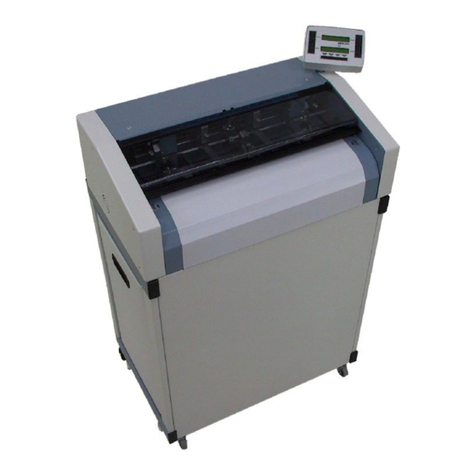
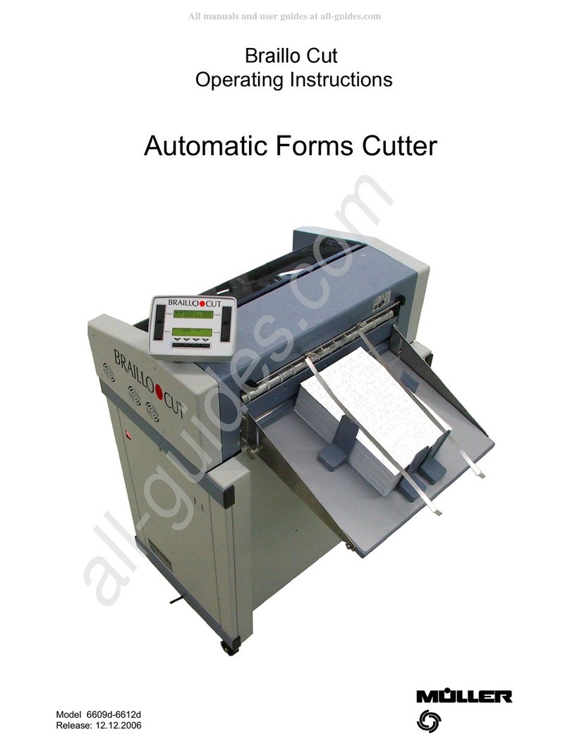
Muller 6609d User manual

Braillo Cut
Operating Instructions
Automatic Forms Cutter
Model 6609d-6612d
Release: 12.12.2006

Mod. 6609d-6612d: Automatic Forms Cutter 13.12.2006
-2-
List of Contents
EC Declaration of Conformity . . . . . . . . . . . . . . . . . . . . . . . . . . . . . . . . . . . . . . . . . . . . . . . . . . . . . . . . . . 4
Safety Instructions . . . . . . . . . . . . . . . . . . . . . . . . . . . . . . . . . . . . . . . . . . . . . . . . . . . . . . . . . . . . . . . . . . . . . . . 5
1. Setting up the machine . . . . . . . . . . . . . . . . . . . . . . . . . . . . . . . . . . . . . . . . . . . . . . . . . . . . . . . . . . . . . . 5
1.1 Selecting a location . . . . . . . . . . . . . . . . . . . . . . . . . . . . . . . . . . . . . . . . . . . . . . . . . . . . . . . . . . . . . . 5
1.2 Unpacking the machine and checking the parts . . . . . . . . . . . . . . . . . . . . . . . . . . . . . . 5
1.3 Parts list . . . . . . . . . . . . . . . . . . . . . . . . . . . . . . . . . . . . . . . . . . . . . . . . . . . . . . . . . . . . . . . . . . . . . . . . . . 6
1.4 Installing the stacker tray . . . . . . . . . . . . . . . . . . . . . . . . . . . . . . . . . . . . . . . . . . . . . . . . . . . . . . . . 6
1.5 Testing the forms cutter . . . . . . . . . . . . . . . . . . . . . . . . . . . . . . . . . . . . . . . . . . . . . . . . . . . . . . . . . 7
1.6 Subassemblies . . . . . . . . . . . . . . . . . . . . . . . . . . . . . . . . . . . . . . . . . . . . . . . . . . . . . . . . . . . . . . . . . . 8
2. Starting up . . . . . . . . . . . . . . . . . . . . . . . . . . . . . . . . . . . . . . . . . . . . . . . . . . . . . . . . . . . . . . . . . . . . . . . . . . . . . 9
2.1 Switching the machine on . . . . . . . . . . . . . . . . . . . . . . . . . . . . . . . . . . . . . . . . . . . . . . . . . . . . . . . 9
2.2 Selecting the program . . . . . . . . . . . . . . . . . . . . . . . . . . . . . . . . . . . . . . . . . . . . . . . . . . . . . . . . . . . 9
2.3 Loading paper . . . . . . . . . . . . . . . . . . . . . . . . . . . . . . . . . . . . . . . . . . . . . . . . . . . . . . . . . . . . . . . . . . . 9
2.3.1 Inserting the paper . . . . . . . . . . . . . . . . . . . . . . . . . . . . . . . . . . . . . . . . . . . . . . . . . . . . . . . . . . . 9
2.3.2 Adjusting the edge blades . . . . . . . . . . . . . . . . . . . . . . . . . . . . . . . . . . . . . . . . . . . . . . . . . . . . 9
2.3.3 Automatic positioning of the forms . . . . . . . . . . . . . . . . . . . . . . . . . . . . . . . . . . . . . . . . . . . 10
2.3.4 Paper adjustment with reader from above . . . . . . . . . . . . . . . . . . . . . . . . . . . . . . . . . . . . . . 11
2.3.5 Paper adjustment with reader from below . . . . . . . . . . . . . . . . . . . . . . . . . . . . . . . . . . . . . . 11
2.4 Starting the forms cutter . . . . . . . . . . . . . . . . . . . . . . . . . . . . . . . . . . . . . . . . . . . . . . . . . . . . . . . 12
2.4.1 Display . . . . . . . . . . . . . . . . . . . . . . . . . . . . . . . . . . . . . . . . . . . . . . . . . . . . . . . . . . . . . . . . . . . . 12
2.4.2 Test cut . . . . . . . . . . . . . . . . . . . . . . . . . . . . . . . . . . . . . . . . . . . . . . . . . . . . . . . . . . . . . . . . . . . 12
3. Operating the machine . . . . . . . . . . . . . . . . . . . . . . . . . . . . . . . . . . . . . . . . . . . . . . . . . . . . . . . . . . . . . 13
3.1 The operating terminal . . . . . . . . . . . . . . . . . . . . . . . . . . . . . . . . . . . . . . . . . . . . . . . . . . . . . . . . . 13
3.1.1 Introduction to the operation of the machine . . . . . . . . . . . . . . . . . . . . . . . . . . . . . . . . . . . 13
3.1.2 Panel keys . . . . . . . . . . . . . . . . . . . . . . . . . . . . . . . . . . . . . . . . . . . . . . . . . . . . . . . . . . . . . . . . . 14

Mod. 6609d-6612d: Automatic Forms Cutter 13.12.2006
-3-
3.1.3 Display messages . . . . . . . . . . . . . . . . . . . . . . . . . . . . . . . . . . . . . . . . . . . . . . . . . . . . . . . . . . 14
3.1.4 Further display functions . . . . . . . . . . . . . . . . . . . . . . . . . . . . . . . . . . . . . . . . . . . . . . . . . . . . 15
3.1.5 Information to the INFO-button . . . . . . . . . . . . . . . . . . . . . . . . . . . . . . . . . . . . . . . . . . . . . . . 15
3.2 The operator level (level 1) . . . . . . . . . . . . . . . . . . . . . . . . . . . . . . . . . . . . . . . . . . . . . . . . . . . . . . 16
3.2.1 Entering parameters . . . . . . . . . . . . . . . . . . . . . . . . . . . . . . . . . . . . . . . . . . . . . . . . . . . . . . . . 16
3.2.1.1 Parameter b) Length . . . . . . . . . . . . . . . . . . . . . . . . . . . . . . . . . . . . . . . . . . . . . . . 16
3.2.1.2 Parameter i) Special Length and j) Program Sequence . . . . . . . . . . . . . . . . . . 17
3.2.1.3 Parameter c) Cut . . . . . . . . . . . . . . . . . . . . . . . . . . . . . . . . . . . . . . . . . . . . . . . . . . 19
3.2.1.4 Parameter d) Counter . . . . . . . . . . . . . . . . . . . . . . . . . . . . . . . . . . . . . . . . . . . . . . 20
3.2.1.5 Parameter e) Counter Function . . . . . . . . . . . . . . . . . . . . . . . . . . . . . . . . . . . . . . 21
3.2.1.6 Parameter m) Programming the fold length . . . . . . . . . . . . . . . . . . . . . . . . . . . . . 22
3.3 The programming level (level 2) . . . . . . . . . . . . . . . . . . . . . . . . . . . . . . . . . . . . . . . . . . . . . . . . 23
3.3.1 Selecting and altering parameters . . . . . . . . . . . . . . . . . . . . . . . . . . . . . . . . . . . . . . . . . . . . . 23
3.3.1.1 Parameter a) Label . . . . . . . . . . . . . . . . . . . . . . . . . . . . . . . . . . . . . . . . . . . . . . . . . 23
3.3.1.2 Parameter f) Speed . . . . . . . . . . . . . . . . . . . . . . . . . . . . . . . . . . . . . . . . . . . . . . . . 24
3.3.1.3 Parameter g) Pause . . . . . . . . . . . . . . . . . . . . . . . . . . . . . . . . . . . . . . . . . . . . . . . . . 24
3.3.1.4 Parameter h) Fine Position . . . . . . . . . . . . . . . . . . . . . . . . . . . . . . . . . . . . . . . . . . 25
3.3.1.5 Parameter k) Reader . . . . . . . . . . . . . . . . . . . . . . . . . . . . . . . . . . . . . . . . . . . . . . . . 26
3.3.1.6 Parameter l) Copy . . . . . . . . . . . . . . . . . . . . . . . . . . . . . . . . . . . . . . . . . . . . . . . . . 27
3.3.2 Programming the OMR routines . . . . . . . . . . . . . . . . . . . . . . . . . . . . . . . . . . . . . . . . . . . . . . . 29
3.3.2.1 Explanation of terms relating to optical mark recognition (OMR) . . . . . . . . . . . . . . 29
3.3.2.2 Entering the 5-digit number for the pattern of marks (code) . . . . . . . . . . . . . . . . . . 32
3.3.2.3 Entering the 5-digit number for the functions . . . . . . . . . . . . . . . . . . . . . . . . . . . . . . 34
3.3.3 Counter function ONLINE # 00 / # 01 . . . . . . . . . . . . . . . . . . . . . . . . . . . . . . . . . . . . . . . . . . . 41
3.4 The technician level (level 3) . . . . . . . . . . . . . . . . . . . . . . . . . . . . . . . . . . . . . . . . . . . . . . . . . . . . 42
3.4.1 Service routines . . . . . . . . . . . . . . . . . . . . . . . . . . . . . . . . . . . . . . . . . . . . . . . . . . . . . . . . . . . . 43
3.4.2 Messages . . . . . . . . . . . . . . . . . . . . . . . . . . . . . . . . . . . . . . . . . . . . . . . . . . . . . . . . . . . . . . . . . . 48
4. Important notes and information . . . . . . . . . . . . . . . . . . . . . . . . . . . . . . . . . . . . . . . . . . . . . . . . . 49
4.1 Cleaning and maintenance . . . . . . . . . . . . . . . . . . . . . . . . . . . . . . . . . . . . . . . . . . . . . . . . . . . . . 49
4.2 Troubleshooting . . . . . . . . . . . . . . . . . . . . . . . . . . . . . . . . . . . . . . . . . . . . . . . . . . . . . . . . . . . . . . . . 50
4.3 Technical data . . . . . . . . . . . . . . . . . . . . . . . . . . . . . . . . . . . . . . . . . . . . . . . . . . . . . . . . . . . . . . . . . . 51
4.4 Technical change of the main PCB·s . . . . . . . . . . . . . . . . . . . . . . . . . . . . . . . . . . . . . . . . . . 52
4.4.1 Connections and electrical settings. . . . . . . . . . . . . . . . . . . . . . . . . . . . . . . . . . . . . . . . . . . . 53
Index . . . . . . . . . . . . . . . . . . . . . . . . . . . . . . . . . . . . . . . . . . . . . . . . . . . . . . . . . . . . . . . . . . . . . . . . . . . . . . . . . . . . . . 55

Mod. 6609d-6612d: Automatic Forms Cutter 13.12.2006
-4-

Mod. 6609d-6612d: Automatic Forms Cutter 13.12.2006
-5-
Safety Instructions
Before operating this machine please read carefully the following instructions for your own
safety and for safe operation of the machine.
This machine may only be operated by trained staff .The manufacturer disclaims liability for
injuries occurring during unauthorized operation.
This equipment must not be installed or altered, and the housing must not be opened, by
anyone other than a trained service technician.
Make sure that the electricity supply conforms with the voltages given on the machine.
This machine may only be operated using the cable supplied.
Do not connect and disconnect the interface connector while the power is switched on. Wait
at least 10 seconds after switching the machine off and on.
Except for the service routines given in the operat ing instructions you should never attempt to
repair the machine yourself. If problems arise call the service technician at your customer
service centre.
Keep long hair, fingers and jewellery well away from rotating machine parts.
1. Setting up the machine
1.1 Selecting a location
The following factors are important in selecting a location for the machine:
- Avoid direct sunlight, heat and damp.
- Always use an earthed socket with no adapter plug.
1.2 Unpacking the machine and checking the parts
Unpack the machine and check that no damage has occurred during transport.
Two persons are required to set up the machine. Hold the automatic forms cutter on the
bars of the base rack and stand it on its feet. Never hold the machine e.g. at the display or
the cover.
Risk of breakage! Remove all PU parts (transport protection).
For your information: You will find the stacker plate (optional) in the waste container.
Fix the machine in position by unscrewing the adjustable feet!

Mod. 6609d-6612d: Automatic Forms Cutter 13.12.2006
-6-
1.3 Parts list
1 Automatic Forms Cutter
1 Abfallbehälter
1 Stacker tray (optional):
1 Tray
1 Left side piece
1 Right side piece
2 Knurled screw
2 Washer
2 Screw
8 Disc spring
2 Washer
4 Paper stop
2 Paper holder
Items , , are fixed to the side pieces , with a nut. The nut is for transport protection only and is not required
for installation.
1.4. Installing the stacker tray
1. Unpack all parts. Unscrew the fasteners , , on the side pieces , . These parts are fixed to the side
pieces with a nut. The nut is only for protection during transport. Make sure that the disc springs are fitted
in the correct position.
2. Screw the side pieces to the stacker tray and hang in position on the back of the machine.
3. Fit the paper holder . To do this, unscrew the clamps on the rod at th e back of the machine and
fasten the paper holder with the screws .
4. Position the 4 paper stops .

Mod. 6609d-6612d: Automatic Forms Cutter 13.12.2006
-7-
Before switching the machine on, test the action of the upper blade as it moves to meet the lower
blade. This is vitally important, as otherwise the cross cutter may be damaged.
1.5 Testing the forms cutter
Before beginning to operate the forms cutter remove the protective covering from the feed plate. If it is not
removed, the paper will become statically charged and will affect the cutting process.
This check is absolutely essential as the machine may have become maladjusted during transport.
Proceed as follows:
1. Unscrew the housing from the right side wall of the forms cutter.
2. Slowly turn by hand the large belt pulley to which the connecting rod is fastened. No strong resistance should
be felt.
3. Raise the upper blade to its maximum position by turning the pulley. From the back of the forms cutter
insert a sheet of paper on the far left between the upper and lower blades and perform a cross cut by
turning the pulley slowly. The cross cutter should begin cutting approx. 10 mm from the left edge.
4. If necessary adjust the engagement of the blades by turning the adjusting screw .
5. Screw the housing in position.
6. Before connecting the power supply check the voltage again.
7. Connect the power supply. The forms cutter is now ready for operation.

Mod. 6609d-6612d: Automatic Forms Cutter 13.12.2006
-8-
1.6 Subassemblies
Subassemblies Illustration
(=Pos.)
Housing and cover sheets 1
Chassis 2
Driving shafts for Randschneider 3
Driving shafts for Tractor 4
Chassis and Platine 5
Safety cover 6
Cross cutter - blade bar 7
Cross cutter - ejector 8
Cross cutter - driving unit 9
Tractor unit 10
Tractor left and right 11
Edge cutter unit 12
Edge cutter left and right 13
Terminal 14
Electronic 15
Stand 16
Fan 17

Mod. 6609d-6612d: Automatic Forms Cutter 13.12.2006
-9-
2. Starting up
2.1 Switching the machine on
The machine is switched on by the power switch. The
display then shows a message for about 3 seconds
(display version, serial no., model no.), which can be held
in the display by pressing the stop button.
When the button is pressed again the current counter
position appears. When the button is released, the
program last used is shown. If any other equipment is
connected, it will return to its starting position (e.g.
lowering stacker).
2.2 Selecting the program
The display shows the program last used. If you wan t to use a different program, you can select it with buttons F1-F4.
New programs can be entered in program slot 00 only, and stored in slots 01-83 (see also Section 3.3 "The
programming level”). Every time the machine is switched on, fixed programs from the EPROM memory overwrite
program slots 84-99.
2.3 Loading paper
2.3.1 Inserting the paper
Open both tractor covers and release the tractor
screws . Set the tractors at approximately the width of
the paper but do not lock them. Insert the paper. Make
sure that the leading edge is cleanly torn off, as
otherwise the paper will not be cut on the cross-
perforation. Now close the tractor covers and position
the paper in the centre of the machine. Use the centre
paper guide as an aid. Fix the screws on one of the
tractors and adjust the tension of the paper by moving
the second tractor. The paper should be neither very
tight nor very loose. Then fix the screws on the
secound tractor.
Fine adjustment: This device can be used to fine adjust
the tractor to a certain position using the adjusti ng wheel
(position the tractor first).
2.3.2 Adjusting the edge blades
Release the screws of the edge blades and fix then after setting to the desired width. T he maximum width is 28
mm (option available: extra wide edge cutter max. 60 mm). The red arrow indicates the cutting position of the edge
blade. After setting the required width, lock both edge blade blocks again.
Fine adjustment: This device can be used to fine adjust the edge cu tter to a certain cutting position using the
adjusting wheel (position the edge cutter first).

Mod. 6609d-6612d: Automatic Forms Cutter 13.12.2006
-10-
2.3.3 Automatic positioning of the forms
After the paper has ben inserted, series 6600 forms cutters position the forms automatically at the bl ade edge on
starting or on changing programs. The central paper guide contains a light-guide fibre optics system, which has two
functions:
1. Recognising end-of-paper
2. Automatic positioning of paper on the cutting edge
If the paper is inserted in the tractors in such a way that it does not reach the optical scanner, the tractors will
transport the paper automatically forwards to the scanner after the Start button has been pressed, and then under
the cross blade for the first cut.
If the paper is inserted in such a way that it already covers the optical scanner, the tractors will m ove in reverse
direction to the scanner after the Start button has been pressed and then forwards under the cross blade.
Due to this automatic positioning the paper can be inserted without any need to position it accurately. Before paper
is inserted in the machine, it is important to chec k that the leading edge of the paper has been clean ly torn off at the
cross-perforation. This is necessary because, due to the automatic positioning of the paper on the cutting edge, the
forms will otherwise not be cut exactly on the cross-perforation.
The machine automatically recognizes the leading edge of the paper and transports it immediately to the cutting
edge. If the leading edge is damaged or if a piece has already been cut off, the machine will not position the paper
correctly with the cross-perforation on the blade e dge. Any correction made using the fine adjustment control will be
automatically applied each time paper is inserted.
We recommend that you tear off one sheet of paper before every new start. This also helps to prevent j amming due
to the cuts made by the edge blades.
Caution!
The end-of-paper light barrier must not be covered by the paper-holder as this means the
paper cannot be detected.
On starting, the machine would run in reverse direction and would eject the paper in reverse
direction into the tractor.
If the paper-holder becomes twisted during continuous operation so that it covers the light
barrier, the forms cutter will not stop at the end of the paper.

Mod. 6609d-6612d: Automatic Forms Cutter 13.12.2006
-11-
2.3.4 Paper adjustment with reader from above
(See also 3.3.1.5, parameter k)
If the operator starts an OMR program, the paper will not be
aligned on the cutting edge. The optical mark reader
evaluates the OMR marks printed on the paper. When the
Start button is pressed the first mark is positioned at a reading
head.
Please note: There are two different positions of ht e reading
head!
1/6" processing:
The adjustment line (AL) must be visible in the groove of
the reading head (see scetch).
1/8" processing:
The adjustment line (AL) must have 0,6 mm distance to the
reading head. Measure the distance always from the middle
of the reading mark.
Adjusting the reading head: The reading head can be moved
in the feeding direction and sideways by loosen the set screws
.
If the adjustment at the reading head is not suffic ent to bring
the reading mark in the position as described above, the
reading area of the adjustment line must be entered one line
before or below under parameter k), .
2.3.5 Paper adjustment with reader from below
(See also 3.3.1.5, parameter k)
With reading from below the OMR mark cannot be detected
when positioning the paper. So you have to make a p unch in
the paper as below.
The adjustment line should be
marked by means of punch pliers before
inserting the paper.
The hole must be punched in the
center of the reading mark.
Please note: There are two different positions of the reading
head!
1/6" processing:
The adjustment line (AL) must be visible in the groove of
the reading head (see scetch).
1/8" processing:
The adjustment line (AL) must have 0,6 mm distancet o the
reading head. Measure the distance always from the middle
of the reading mark or from the middle of the hole.
After pressing the Start - button the first reading mark is
positioned at the reading head.
Adjusting the reading head: The reading head can be moved
sideways by the set screw and in the direction of feed by
moving the plate . If the adjustment at the reading head is
not sufficent to bring the reading mark in the position as
described above, the reading area of the adjustment line must
be entered one line before or below under parameter k), .

Mod. 6609d-6612d: Automatic Forms Cutter 13.12.2006
-12-
2.4 Starting the forms cutter
When the paper has been positioned by pressing the Start button (Section 2.3.3), the word READY !!! appears in the
display, or if an OMR program is being used the word ADJUST. To start the machine, press the Start button again
to begin continuous operation.
2.4.1 Display
The starting speed increases continuously during cutting of the first sheets, until the set maximum sp eed is reached.
During continuous operation the fine position (cutting edge), the feed rate and the pause between two forms can be
altered. The preset counter, the actual counter and the group counter are also shown.
F1 - Fine position 1/192" reverse
F2 - Fine position 1/192" forward
F3 - Alter feed rate
(Level 1 to 7= maximum speed)
F4 - Alter pause
(Level 7 to 0, 7= longest pause)
All these changes will be automatically saved in the current program.
2.4.2 Test cut
By pressing the Start and Stop buttons simultaneously it is possible to cut single sheets as a test. When the Stop
button is pressed, the forms cutter always stops at the end of the current cycle. The paper is positioned with the
perforation at the blade edge.

Mod. 6609d-6612d: Automatic Forms Cutter 13.12.2006
-13-
Operator Level Technician LevelProgramming Level
New programs are always entered in PROG 00
3. Operating the machine
The operation of the machine is divided into three levels:
Areas which are not intended for the operator are protected by special access options.
On the programming level all function parameters of the paper cutting machine can be accessed and programs can
be set up and saved.
The technician level operates in an additionally protected area. Service routines can be started. Info rmation about the
condition of the machine can be read.
3.1 The operating terminal
The operating terminal is on the right-hand side of the machine.
On this terminal are:
4 large buttons PROG, INFO, START and STOP, two LEDs each containing 2 lines for 20 character s, and 4 small
multifunction buttons F1-F4. The functions of these buttons are always shown in the lower display.
3.1.1 Introduction to the operation of the machine
Explanation of terms
Parameter Before forms can be cut, a number of different values have to be set, such as sheet length,
type of cut or speed. These values are called parameters.The parameters are entered via
the terminal.
program A program consists of several parameters. The programs are saved in the terminal. Up to
100 programs can be saved. The programs saved are numbered continuously from 00 - 99.
Program structure Imagine the arangement of the programs, each with its individual parameters, like a card file.
Each program represents one index card. The individual parameters are recorded on the
index card.
Program In program selection mode, any program that has been saved can be selected.
selection mode To do this the "function buttons” F1, F2, F3, und F 4 are used. When the desired program
appears on the upper left display, the machine can be started by pressing the Start button.
The slots for working programs are numbered from >01< to >99<.
Parameter mode Parameter mode can be called from program selection mode by pressing the Prog button.
In parameter mode two basic functions can be selected:
1. Parameter selection mode
2. Parameter input mode

Mod. 6609d-6612d: Automatic Forms Cutter 13.12.2006
-14-
The PROG and INFO buttons have no function during continuous operation.
3.1.2 Panel keys
The 4 panel keys have the following functions:
PROG The PROG button switches between the functions program selection and parameter selection.
INFO The INFO button gives information referring to this instruction manual.
If the OMR system is used during STOP the code is d isplayed.
(For service functions see Section 3.1.5).
START This button starts the machine.
STOP When the STOP button is pressed, the machine will stop at the end of the current cycle.
3.1.3 Display messages
The following messages can appear on the display:
PAPER ??? If there is no paper in the forms cutter the word P APER ??? will appear in the lower display and
the machine will stop. The forms cutter also stops at the end of the paper.
COVER ??? If the transparent cover is opened or even just sl ightly lifted during operation, the lower display
will show COVER ??? and the machine will stop at the end of the current cycle.
READY !!! This message appears after the paper has been positioned at the blade edge before starting
the machine. When the Start button is then pressed, continuous operation begins.
CALL SERVICE If a 3-digit number (e.g. 031) is shown, this is a sign of malfunction. Make a note of the 3-digit
number and inform the service technician. (For service messages see Section 3.4.2),
INTERFACE The interface connection on the machine or on an additional machine is defective. The service
technician should be informed.
ID-CHIP The ID-chip on the main board is missing or is defective - inform service technician.
COOLING FAN The filter needs cleaning.
Additional fan defective (applies to model 6611/6612 only) - inform service technician.
ADJUST When using the OMR system (the adjustment line is w ithin the groove of the reading head) the
reading head can now be adjusted. For further information see Section Reader.
READ ERROR The code that has been detected is shown in the lower window on the display
(e.g. 0000000001001001). For further information see Section Reader/Read errors.
STOP Appears when the Stop button is pressed.

Mod. 6609d-6612d: Automatic Forms Cutter 13.12.2006
-15-
3.1.4 Further display functions
SLOW FLASHING of numbers indicates that input is possible. The set values can be altered or new
values can be entered or selected.
FAST FLASHING of numbers indicates that the next working step must now be carried out, e.g.
pressing a function key to carry out or end an operation.
DISPLAY TEXTS All texts in the display are available in various languages which can be obtained by
starting the appropriate service number (see Sectio n 3.4.1 SERVICE ROUTINES).
(R) The sign (R) in the operating instructions stands for "rotating function", i. e. after the
last value or position has been reached, the first value or position will reappear.
In addition all keys which display several responsi ve values have a repeat function, i.e. by holding t he button down
it repeats its function.
..... Panels with a grey background in the operating instructions indicate a flashing display.
See above for notes on the flashing speed.
3.1.5 Information to the INFO-button
After pressing the INFO-button a number appears on the display. This number represents sections
- as the table shows - in the operating manual.
INFO-Nr. section contents
1 2.2 Selecting the program
2 3.3.1.1 Parameter a) Label
3 3.2.1.1 Parameter b) Length
4 3.2.1.3 Parameter c) Cut
5 3.2.1.4 Parameter d) Counter
6 3.2.1.5 Parameter e) Counter Function
7 3.3.1.2 Parameter f) Speed
8 3.3.1.3 Parameter g) Pause
9 3.3.1.4 Parameter h) Fine Position
10 3.2.1.2 Parameter i) Special Length
11 3.2.1.2 Parameter j) Program Sequence
12 3.3.1.5 Parameter k) Reader
13 3.3.1.6 Parameter l) Copy
14 3.3.1.7 Parameter m) Programming the fold length

Mod. 6609d-6612d: Automatic Forms Cutter 13.12.2006
-16-
3.2 The operator level (level 1)
After switching the machine on the operator can carry out various functions. He can:
- select and start programs (00 - 99).
- browse through parameters b) - e) and possibly also i) and j), if parameter b) = 000, in all programs.
- alter parameter d) COUNTER in all programs.
- Change parameter m) fold length in all programs.
- alter parameters b) - e) (possibly also i) and j))in program slot 00.
3.2.1 Entering parameters
After the machine is switched on, the message PROGRAM - SELECT appears on the display. The desired program
can be selected by pressing buttons F1-F4. The program selected then appears in the left upper display.
Press the Prog button to obtain PARAMETER - SELECT. Use buttons F1 and F2 to browse through the
parameters.
3.2.1.1 Parameter b) Length
In the Length parameter you can set the FORM LENGTH . The form length is measured in 1/6" (1 inch = 25. 4mm)
or 1/8" line space. Measure the form first on the plexiglass cover. Give the full length from perforat ion to perforation
(including double cuts where necessary). The 1/6" o r 1/8" step also applies when using the OMR system. If a form
is to be cut into several pieces, this can be enter ed with the Special Length program i), j).
F4 - Press Input
Select length:
F1 - Select number (0-9) (R)
F2 - Current write position =_ (R)
F3 - 1/6" or 1/8" length step
F4 - Exit

Mod. 6609d-6612d: Automatic Forms Cutter 13.12.2006
-17-
3.2.1.2 Parameters i) Special Length and j) Program Sequence
Before parameters i) and j) can be shown at the operator level, you must input the following information.
Select parameter b) and set Length to 000.
Special Length is only possible with Length 000. Sp ecial
Length can not be used together with the OMR system.
Select parameter c) and enter the length step for Special
Length (1/6", 1/8" or 1/24").
The length step in parameter b) is not applicable!
Parameter i) Special Length
Here you can enter up to 4 different lengths. The order is not important at this point.
The sequence of lengths is set in parameter j).
F4 - Press Input
Enter length:
F1 - Select number (0-9) e.g. 10x1/6" (R)
(1/6" is set in parameter c) )
F2 - Current write position =_ (R)
F3 - Length no. 1-4 (i.e. up to 4 different lengths can be
entered) (R)
F4 - Exit

Mod. 6609d-6612d: Automatic Forms Cutter 13.12.2006
-18-
Parameter j) Program Sequence
The lengths in parameter i) can now be entered in the desired sequence under the numbers 1-9. The machine
passes through all positions from 1-9 in every cycle. When length 0 is entered, this position is passed over without
action in the program sequence.
F4 - Press Input
F1 - Sequence (1-9) (R)
F2 - Length 1-4 or 0 from parameter i) (R)
F3 - Form will be chopped
Form will not not be chopped
F4 - Exit
Multiple distribution of lengths 1-4 from parameter i) among positions 1-9 is also possible. In additi on, it is possible
to decide at each position (1-9) whether the length 1-4 displayed here is to be performed completely or whether the
form is to be chopped.
Chopping witdh: 3/6" means that a feed length of 2" will be cut with 4 cycles (1 cycle = 3/6").
When using counter function ONLINE #00/#01 (see section 3.3.3) note the following:
The function entered under line #01 is carried out until the section before the last section is reached.
The function entered under line #00 is carried out when the last section is reached.
Possible cuts with Special Length:
The following example is stored in the machine under program slot 99 (fixed program):
Parameter i) Special Length (1/6" is set in Length c)):
No. 1 - 002 x 1/6"
No. 2 - 004 x 1/6"
No. 3 - 020 x 1/6"
Parameter j)
Program sequence:
1.) Length 2
2.) Length 3
3.) Length 1
4.) Length 3
5.) Length 1
6.) Length 3
7.) Length 2
8.) Length 0
9.) Length 0
The type of cut in our example is ‘do not chop’.
But it could also be ‘chop’, e.g. in program sequence i), point 6.), length 3.

Mod. 6609d-6612d: Automatic Forms Cutter 13.12.2006
-19-
3.2.1.3 Parameter c) Cut
Here you can set the type of cut (single cut, double cut or only edge cut without cross cut), the width of cut
and the cut width step (1/6", 1/8" or 1/24") for double cuts.
Single cut is obtained by entering e.g. 0 * 1/6" or 0 * 1/8" f or the width
(0 = multiplier).
For Double cut the desired waste area is set by entering a multipl ier > 0;
e.g width: 2 * 1/6" (2 = multiplier). Thus in this case the waste area would be 2 * 1/6"
long. Any leftovers longer than this will automatically be chopped.
Edge cut can be set by entering cut width step = NO CUT.
F4 - Press Input
F1 and F2 - Multiplier for cut width step (0-9)
F3 - Cut width step (NO CUT, 1/6", 1/8" or 1/24") (R)
z.B.: 0 x NO CUT = No cross cut
0 x 1/6" = Single cut
2 x 1/8" = Double cut (at the upper and the
lower edge of the form 1/8" will be
cut away)
Possible cuts:
No cross cut -
only the margins will be cut away -
Parameter c) 0 x NO CUT
Single cut
Parameter c) 0 x 1/6"
or 0 x 1/8"
or 0 x 1/24"
Double cut
The piece cut away can be min. 1/24", max.
1 1/2" wide and is distributed symmetr cally
on both sides of the perforation. Wider
double cuts can be programmed using
parametersi) and j).

Mod. 6609d-6612d: Automatic Forms Cutter 13.12.2006
-20-
3.2.1.4 Parameter d) Counter
In this parameter a programmable counter can be preset. It is used if on reaching a given number of fo rms
a function must be carried out which has been set i n parameter e) Counter Function. In addition the SUB-counter
(= group counter) and the ACT-counter (= actual) can be set at 00000.
F4 - Press Input
F1 - Select number (0-9) (R)
F2 - Current write position =_ (R)
F3 - Set SUB-counter at 00000
(first time F3 is pressed)
The SUB-counter is used for all operations with counter
functions (except NONE).
F3 - Set ACT-counter at 00000
(second time F3 is pressed)
The ACT-counter can be used as a daily counter (or for
a particular job).
F4 - Exit
Other manuals for 6609d
1
This manual suits for next models
7
Table of contents
Other Muller Cutter manuals
Popular Cutter manuals by other brands

RODCRAFT
RODCRAFT RC7170 Operator's manual

Swisher
Swisher RC11544CL owner's manual

Thunder Laser
Thunder Laser MARS-90 user manual

Milwaukee
Milwaukee HEAVY DUTY M12 FCOT Original instructions

CHANCE
CHANCE C403-2979 Instructions for operation

Wolfcraft
Wolfcraft LC 100 Translation of the original operating instruction