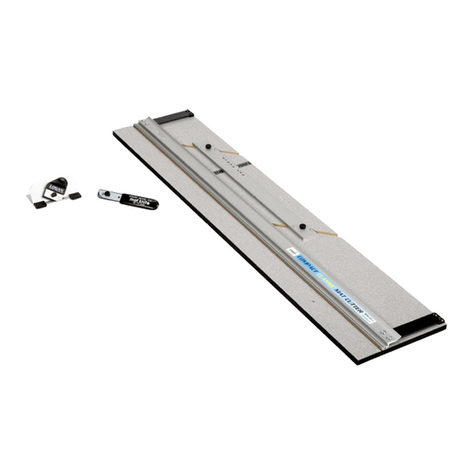
Logan simplex plus 760 Manual

SIMPLEX PLUS
MAT CUTTER MODELS 750 & 760
www.logangraphic.com
Purchase Date
ID Number (on bottom of board)
Date (on bottom of board)
INSTRUCTION AND OPERATION MANUAL
Mat cutting system with laminate board, production
stops, parallel mat guide, 27" squaring arm, plus straight
and bevel cutting heads
PROFESSIONAL SERIES
For best results use only
authentic Logan blades
Use Logan Blade #270
Logan Graphic Products, Inc.
1100 Brown Street
Wauconda, IL 60084 USA
Phone (847) 526-5515 Fax (847) 526-5155
Toll Free (800) 331-6232
L759N2 5/07
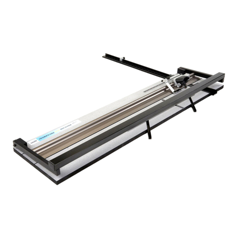
Model 750 Simplex Plus - 40" mat cutter
Model 760 Simplex Plus - 60" mat cutter

SIMPLEX PLUS
MAT CUTTER MODELS 750 & 760
Congratulations on your purchase of the
Logan Simplex Plus Mat Cutter. The
Simplex Plus is a well designed mat cutter
with professional features to produce
professional results. Features like
production stops, parallel mat guide in
aluminum channels and anti-crawl pin
make the Simplex Plus an efficient yet cost
effective tool for artists, photographers and
crafters alike. This instruction manual is
written to acquaint you thoroughly with this
product. Please take some time to
familiarize yourself with it before cutting.
You will find that the time taken will be
well worth it and you will be cutting quality
mats in no time.
Parts schematic available online at www.logangraphic.com
INTRODUCTION: TABLE OF CONTENTS:
Warranty
Logan Graphic Products, Inc. (“Logan”) warrants the 750 SIMPLEX PLUS to be free from defects in parts and
workmanship for a period of two years from the date of original purchase. Logan warrants that it will either repair or
replace, in its sole discretion, any necessary replacement parts found to be defective. Should the product need to be
returned to Logan for repair or replacement parts, authorization for any return must come from Logan in writing. Costs
of returning the product to Logan, including insurances, shall be borne by the purchaser. Logan shall not be liable for
any damages or losses, incidental or consequential, direct or indirect, arising from the use of this product. This
warranty extends only to the original purchaser and is not assignable or transferable. This warranty is in lieu of all
other warranties, expressed or implied.
Introduction 1
Warranty 1
Product Description 2
Identification Of Machine Components 2
Orientation
A. Unpacking/Check of Contents 3
B. Assembly 3
C. Blade Installation 4
Operation
A. Straight Cutting a Board To Size 4
B. Cutting a Beveled Opening Using Marked Lines 5
C. Cutting a Beveled Opening Using One Production Stop 6
D. Cutting a Beveled Opening Using Two Production Stops 7
E. Cutting a Straight Opening 7
Adjustments & Maintenance
A. Blade Depth Adjustment 8
B. Re-Parallel The Mat Guide 8
C. Re-Square the Squaring Arm 8
D. Helpful Hints 9
Trouble Shooting 9
Creative Matting Guide
A. Double Mat 10
B. Off-Set Corner Mat 10
C. Inlay Mat 10
Logan Graphic Products Inc., 1100 Brown Street, Wauconda, IL 60084 Toll Free 1 800 331 6232 www.logangraphic.com
1

SIMPLEX PLUS
MAT CUTTER MODELS 750 & 760
750 Simplex Plus - 40” Laminated Cutting Board with Mat Guide in aluminum channels, two guide rail stops, 27” Squaring Arm, Squaring Arm Stop, Slip Sheet, Straight and
Bevel Cutting Heads, Logan Screwdriver and 1 five pack of Logan #270 blades.
760 Simplex Plus - 60” Laminated Cutting Board with Mat Guide in aluminum channels, two guide rail stops, 27” Squaring Arm, Squaring Arm Stop, Slip Sheet, Straight and
Bevel Cutting Heads, Logan Screwdriver and 1 five pack of Logan #270 blades.
IDENTIFICATION OF MACHINE COMPONENTS
Simplex Plus Cutting Board
Guide Rail - Used to guide cutting heads while in use.
Mat Guide - Used to set the border width of a mat and keep the mat in
position.
Squaring Arm - 27” board mounted 90 degree bar used to hold mats square
when cutting and as stop when bevel cutting.
Cutting Board - Laminated surface base board of machine.
Production Stops - Used when production cutting to speed up the process of
mat cutting.
Slip Sheet - Scrap piece of mat board placed underneath the mat being cut.
Produces a cleaner cut and longer blade life.
Squaring Arm Stop - Used when downsizing mat board.
702 Bevel Cutting Head
Start and Stop Indicator - Line which shows where to begin and end cut.
Retaining Screw - Screw which keeps blade safely in slot when not in use.
Anti-Crawl Pin - Prevents cutting head from creeping forward during initial penetration of blade
into mat.
Nylon Guides - Guides which allow Bevel Cutting Head to hook onto
Guide Rail.
701 Straight Cutting Head
Blade Holder - Block which holds blade in place while cutting. Has three
separate depth settings.
Blade Cover - Covers blade on Blade Holder.
Blade Screw - Holds blade in place inside Blade Holder.
Guide Rail
Mat Guide
Cutting Board
Nylon Guides
Start and Stop Indicator
Retaining Screw
Anti-Crawl Pin
Blade Holder
Blade Cover
Blade Screw
PRODUCT DESCRIPTION
Production
Stops
27” Squaring Arm
Slip Sheet
Squaring Arm Stop
Logan Graphic Products Inc., 1100 Brown Street, Wauconda, IL 60084 Toll Free 1 800 331 6232 www.logangraphic.com
2

Logan Graphic Products Inc., 1100 Brown Street, Wauconda, IL 60084 Toll Free 1 800 331 6232 www.logangraphic.com
3
SIMPLEX PLUS
MAT CUTTER MODELS 750 & 760
A. UNPACKING/CHECK OF CONTENTS
Items packed loose in the box include:
1. Straight Cutting Head
2. Bevel Cutting Head
3. 27” Squaring Arm
4. Mat Guide
5. Aluminum Guide Channels (2)
6. Channel Screws (4)
7. Guide Rail Stops (2)
8. Squaring Arm Stop (1)
9. Logan Screwdriver
10. Five Pack of #270 blades
11. #750 Base Board (not shown)
12. Slip Sheet (not shown)
13. Instruction Manual (not shown)
If there are any missing or damaged items please call customer service
immediately at 1-800-331-6232
ORIENTATION
The procedure detailed in the following
instructions refer to the right and left side, and
the top and bottom of the machine as shown.
Fig. 1
B. ASSEMBLY
Mat Guide
1. Press each aluminum mat guide channel into board
slots with rounded end towards the Guide Rail.
Insert the four small guide rail channel screws from
the UNDERSIDE of the board and tighten. Fig. 3
2. To install the Mat Guide loosen each knob three full
turns. Hold the mat guide at either end and evenly
drop the Mat Guide into the aluminum channels and
tighten the knobs.
3. To loosen, turn knobs counterclockwise and slide.
Fig. 4
Fig. 1
Fig. 3 Fig. 4
Top
Right
Left
Bottom Fig. 2
1.
2.
3. 4.
5.
6.
7.
8.
9.
10.
Squaring Arm
Use the line-up tool found in the squaring arm slot to line up
the slot in the board with the slot in the squaring arm. Use the
two larger machine screws provided to tighten the squaring
arm into the board slot. These machine screws are found
screwed into the board for shipping purposes. Fig. 4
Slip Sheet
A Slip Sheet is a piece of scrap matboard placed underneath
the mat to be cut when bevel cutting. The Slip Sheet must be
at least as long as the mat being cut and at least 4” wide. This
protects the blades while cutting and produces a better cut.
Fig. 5
NOTE: It is important not to continue to cut in the same
spot of the Slip Sheet as this can cause curves in the
cut. Replace Slip Sheet as necessary.
Fig. 5
Line-Up Tool
Fig. 4
Mat Board Slip Sheet

Logan Graphic Products Inc., 1100 Brown Street, Wauconda, IL 60084 Toll Free 1 800 331 6232 www.logangraphic.com
4
SIMPLEX PLUS
MAT CUTTER MODELS 750 & 760
C. BLADE INSTALLATION
701 Straight Cutting Head
Remove the Blade Screw and the Blade Cover from the Blade Holder. Place one #270 blade, sharp edge
down, in the slot on the Blade Holder and line up the hole in the blade with the desired depth setting.
Replace the Blade Cover and Blade Screw. Fig. 4
The #701 has three depth settings:
Top setting - safety setting
Middle setting - standard thickness mat board (4 ply)
Bottom setting - 3/16” foamboard
NOTE: Always have the three holes on the Blade Cover lined up exactly with the three holes
on the Blade Holder before replacing the Blade Screw.
702 Bevel Cutting Head
NOTE: The following must be done before loosening blade knob.
Loosen the Retaining Screw found on the back side of the Cutting Head until flush with the surface of
the base. This allows the Blade Holder to tilt back all the way for blade change. Slide one #270 blade
all the way in the back of the Blade Holder as shown. Fig. 5
NOTE: The hole in the blade is not designed to line up with the Blade Screw.
Re-tighten the Blade Knob and tilt the Blade Holder down allowing the tip of the blade to enter the
Blade Slot. Retighten the Retaining Screw.
Fig. 4
Fig. 4
Fig. 5 Blade Slot
OPERATION
A. STRAIGHT CUTTING A BOARD TO SIZE
1. Remove the Mat Guide and Slip Sheet before straight cutting.
2. Set the Squaring Arm Stop at the number on the scale which you want your mat to be cut
down to.
3. Lift the Guide Rail and place a sheet of matboard against the Squaring Arm and slide the mat
board to the right against the stop. Make sure that it is squarely against the Squaring Arm.
4. Hook the Straight Cutting Head onto the Guide Rail past the end of the board to be cut. Grasp
the handle as shown in the picture and pull the Straight Cutting head towards you. Keep
constant downward pressure on the Straight Cutting Head and the Guide Rail as you make
your cut. Fig. 1
CAUTION: Be careful to control the Straight Cutting Head as it breaks through the end of the
matboard as it will tend to “jump” towards you.
Fig. 1
Squaring
Arm Stop

SIMPLEX PLUS
MAT CUTTER MODELS 750 & 760
Logan Graphic Products Inc., 1100 Brown Street, Wauconda, IL 60084 Toll Free 1 800 331 6232 www.logangraphic.com
5
B. CUTTING A BEVELED OPENING USING MARKED LINES
EXAMPLE: Cutting a mat with a 2” border.
1. To re-install the Mat Guide, loosen the black knobs three turns and with the raised edge
towards the Guide Rail, line up the Mat Guide with the parallel slots. Hold the Mat Guide at
either end and evenly drop the Mat Guide into the aluminum channels and then tighten the
black knobs.
2. Set the Mat Guide to the desired border width. For example for a 2” border align the front of
the Mat Guide at the 2” mark and tighten the black knobs. Fig. 2
3. Make sure the Slip Sheet is in place before bevel cutting. You must use a Slip Sheet. The
straight cut slot underneath the Guide Rail is used for straight cutting only.
4. Place the mat color side down under the Guide Rail, against the Mat Guide and down against
the Squaring Arm. Fig. 3
5. Using a pencil, draw a line down the full length of the back of the matboard. Repeat this for
the remaining three sides. Fig. 4
6. Hook the 702 Bevel Cutter on to the Guide Rail.
7. Position the cutter so that the Start and Stop Indicator line lines up with the marked line
closest to the top of the machine. Fig. 5
8. With the left hand depress the Anti-Crawl Pin and firmly pivot the Blade Holder down into the
mat. Fig. 5
9. Release the Anti-Crawl Pin and pull the cutting head towards you until the Start and Stop
Indicator line lines up with the line on the matboard closest to you. DO NOT GO PAST THE
LINE! Fig. 6
NOTE: It is essential to keep even downward pressure on the Blade Holder as you cut.
10. Rotate the Blade Holder back up to the neutral position, turn the mat 1/4 turn to the right and
repeat steps 7 through 9 for the remaining three sides to finish the mat.
Fig. 2
2”
Fig. 3
Mat Board Slip Sheet
Fig. 4
Fig. 5 Fig. 6

Logan Graphic Products Inc., 1100 Brown Street, Wauconda, IL 60084 Toll Free 1 800 331 6232 www.logangraphic.com
6
SIMPLEX PLUS
MAT CUTTER MODELS 750 & 760
Fig. 2
C. CUTTING A BEVELED OPENING USING ONE PRODUCTION
STOP
EXAMPLE: Cutting a mat with a 2” border.
1. Set the Mat Guide to the desired border width. For example, for a 2”
border, align the front of the Mat Guide at the 2” mark and tighten the Black Knobs. Fig. 1
2. Place the mat to be cut into the machine colored side down with the
Slip Sheet underneath and lower the guide rail.
3. Install the guide rail stop onto the guide rail and tighten at the 2” mark on the scale. Fig. 2
4. Using a pencil, mark a line along the full length of the mat board using the guide rail as a
guide. Fig. 3. Turn the mat 1/4 turn to the right before cutting.
5. Hook the bevel cutting head onto the guide rail and slide it up until the Start and Stop
indicator lines up with the marked line closest to the top of the machine.
6. With the left hand, depress the anti-crawl pin and pivot the blade holder to insert the blade
into the mat. Fig. 4
7. Release the anti-crawl pin and pull the bevel cutting head towards you until it gently contacts
the guide rail stop. Pivot the blade holder up to remove the blade from the mat.
8. Lift the guide rail and turn the mat 1/4 turn to the right.
9. Slide the bevel cutting head up to the cut just made in the mat and line up the start and stop
indicator for the next cut. Continue steps 6 through 9 to finish mat.
NOTE: In order for the production stops to be accurate, the blade depth must be set properly.
If using the stop produces an overcut or undercut, a blade depth adjustment may be needed.
(see page 8) 2”
Fig. 1
2”
Fig. 3
Fig. 4

SIMPLEX PLUS
MAT CUTTER MODELS 750 & 760
Logan Graphic Products Inc., 1100 Brown Street, Wauconda, IL 60084 Toll Free 1 800 331 6232 www.logangraphic.com
7
Fig. 5
D. CUTTING A BEVELED OPENING USING TWO PRODUCTION
STOPS
EXAMPLE: Cutting a mat with a 2” border.
NOTE: This method should only be used when cutting multiple numbers of mats that have the
same outside and inside dimensions.
1. Set the Mat Guide to the desired border width. For example for a 2”
border align the front of the Mat Guide at the 2” mark and tighten the Black Knobs.
2. Place the mat to be cut into the machine colored side down with the
Slip Sheet underneath and lower the guide rail.
3. Using a pencil, mark a line along the full length of the mat board using the guide rail as a
guide. Fig. 3. Turn the mat 1/4 turn to the right before cutting.
4. Install the first guide rail stop onto the guide rail and slide it past the far end of the matboard
but do not tighten it.
5. Install the second guide rail stop onto the guide rail and tighten at the 2” mark on the guide
rail scale.
6. Hook the bevel cutting head onto the guide rail and slide up until the start & stop indicator
lines up with the marked line closest to the top of the machine. Fig. 4
7. Slide the top guide rail stop towards you until it makes contact against the bevel cutting head
and tighten. Fig. 5
8. Both guide rail stops are now set to make repeated opposite side cuts on a multiple number
of mats of the same size. To then cut the other sides of the mats, reset the top stop as you
did in step 6. and cut the remaining sides.
E. CUTTING A STRAIGHT OPENING
Example: Cutting a mat with a 2” border
1. Set the Mat Guide to the 2” mark on the scale and retighten the black knobs.
2. Place the mat to be cut into the machine colored side down with the Slip Sheet
underneath and lower the Guide Rail.
3. Using a pencil, mark a line along the full length of the matboard using the Guide Rail
as a guide. Fig. 1. Repeat this for remaining three sides.
4. Using the Straight Cutting Head, align the top scribe line with the top border line
and press down on the handle until the cutting head sits flat on the matboard so the
Nylon Guides hook onto the Guide Rail lip. Fig. 2
5. Pull the Straight Cutting Head until the bottom scribe line lines up with the bottom
border line. Repeat until all borders are cut. Fig. 3 Fig. 3Fig. 2
Fig. 1

Logan Graphic Products Inc., 1100 Brown Street, Wauconda, IL 60084 Toll Free 1 800 331 6232 www.logangraphic.com
8
SIMPLEX PLUS
MAT CUTTER MODELS 750 & 760
ADJUSTMENTS & MAINTENANCE
A. BLADE DEPTH ADJUSTMENT- BEVEL CUTTING HEAD
Tools needed: Screwdriver, Ruler
1. Hold the 702 Bevel Cutter upside down in your hand with the blade activated in the cutting position.
2. Looking at the tip of the blade, measure the exposed amount with a ruler at the same angle as the blade. For
standard thickness mat board (4 ply) only 1/8” of blade should be seen. To adjust, find the screw head recessed
below the bottom of the surface of the cutting head near where the blade is coming out. Fig. 4
3. Turning the screw to the right (clockwise) will decrease the blade depth, the left (counterclockwise) will increase
the blade depth. Not all matboard requires 1/8”. Thicker matboard will require more. Always have the blade depth
set so that the Slip Sheet is scored only slightly. Cutting even half way through the Slip Sheet is entirely too much
blade depth. This extra blade depth allows the blade tip to flex and cause hooks and curves in the cut.
Extra blade depth can also cause the Start and Stop indicator to be incorrect which results in overcuts. This test and
adjustment needs to be done periodically as mat board has many variances of thickness and the depth can increase
itself over time with regular use.
1/8”
Blade Depth
Screw
Fig. 4
B. RE-PARALLEL THE MAT GUIDE
Tools needed: Phillips Screwdriver, Ruler.
To re-parallel the Mat Guide, first determine that the Mat Guide is out of parallel by doing a parallel test.
Parallel Test:
1. Lock the Mat Guide at the 2" mark on the scale. Fig. 1
2. Place a scrap piece of matboard under the Guide Rail and up against the Mat Guide at the top end of the machine.
3. Using a pencil, mark a line across the mat.
4. Slide the mat all the way down to the bottom where you are standing keeping the mat against the mat guide but
not against the Squaring Arm.
5. Draw a line across the mat.
6. The piece of matboard should now appear to only have one single line across it. If the two lines drawn do not line
up with each other, the Mat Guide needs to be re-paralleled.
To Re-parallel:
1. Release the Mat Guide.
2. Use a Phillips head screwdriver to loosen the screws on either side of the black knobs one turn each. There are
four screws total to be loosened this way.
3. Place a metal ruler or suitable straight edge between the Mat Guide and the Guide Rail. Fig. 2
4. Slide the Mat Guide against the straight edge and the Guide Rail. Make sure both the Mat Guide and the Guide
Rail are making solid contact on both sides of the straight edge.
5. Re-tighten the Black Knobs first.
6. Then re-tighten the four screws. Do another parallel test to ensure that the Mat Guide is now parallel.
Fig. 1
Fig. 2
Place straight edge here
2”
C. RE-SQUARE THE SQUARING ARM
Tools needed: Screwdriver, Carpenter’s Square.
ATTENTION: It is common for 32” x 40” sheets of mat board to be un-square when bought. Take
this into account before making any adjustments to the Squaring Arm.
Before making any adjustments to the squaring arm, make sure that the machine is truly out of square, not
the mat board, by using the squareness test.
Squareness Test
1. Place the carpenter’s square against the right hand side of the guide rail and down against the
squaring arm. Fig. 1 Look to see if there are any gaps between the framing square and the
squaring arm. If so, the squaring arm needs to be adjusted.
Fig. 1
Place square here
SIMPLEX PLUS
MAT CUTTER MODELS 750 & 760
Logan Graphic Products Inc., 1100 Brown Street, Wauconda, IL 60084 Toll Free 1 800 331 6232 www.logangraphic.com
9
Fig. 2
To re-square
1. By looking at where the gap is you can determine which way the squaring arm needs to go in
order to be square again.
2. Remove the squaring arm and locate the three screws inside of the slot.
3. Adjust only two screws A&B. DO NOT ADJUST C. To adjust, you must turn screws A & B in
equal but opposite directions. To move the far right end of the squaring arm towards the top
end of the machine, turn adjustment screw B inward (clockwise) about a quarter turn and
adjustment screw A outward (counter-clockwise) a quarter turn. Fig. 2
4. Re-install the squaring arm and check for square. This is a trial and error method, in some
cases more than a quarter turn is needed, in some cases less.
D. HELPFUL HINTS
1. Always store your Simplex Plus Mat Cutter flat. Never stand the Mat Cutter up against a wall
for any period of time. This can cause the Mat Cutter base to bow.
2. If you need to clean the Guide Rail, only use an evaporating solvent (lighter fluid, alcohol)
that will leave no residue. Do not lubricate the Guide Rail as the substance will soften the
Nylon Guides on the cutting heads causing them to bind on the Guide Rail.
3. The Bevel Cutting head has a “spring back” feature installed. This spring action is not
intended to pull the blade up out of the mat after a cut. It is a safety device to prevent the
blade from dropping down into the blade slot and cutting into a table, your hand, etc. when
not in use.
4. A NOTE ON BLADE LIFE:
No two blades may last the same. It is a good idea to install a new blade before starting a
new project to insure best cutting results.
Note: Use only authentic Logan blades
Problem
Hooks or Curves
Overcut on Top Cut
TROUBLE SHOOTING
Solution
■Use authentic Logan blades only.
■Blade depth set too deep. (see page 8)
■Blade is dull.
■Blade is catching on previous cut in Slip
Sheet. (see page 4)
■Uneven pressure being applied to Cutting
Head during cut.
(see page 6)
■Cutting Head crawling forward as you
insert the blade. Use Anti-Crawl Pin. (see
page 6)
■Blade depth set too deep.
(see page 8)
■Stops not set properly.
Problem
Overcut on Bottom Cut
Mat Borders Uneven
Ragged Bevel Cut
Not Cutting Through
Solution
■Adjust where you start and stop in relation to Start and Stop indicator.
■Not keeping mat squarely against squaring arm when cutting.
■Mat Guide not parallel. (see page 8)
■Cutting without a Slip Sheet. (see page 4)
■Slip Sheet is worn out. (see page 4)
■Not changing the blade often enough.
■Machine not on a level surface. (see page 9)
■Not using a Slip Sheet at least as long as the mat you are cutting.
(see page 4)
■Slip Sheet not as wide as Guide Rail.
■Blade depth set too shallow. (see page 8)
■Uneven pressure being applied to cutting head during cut.
(See page 6)

SIMPLEX PLUS
MAT CUTTER MODELS 750 & 760
Logan Graphic Products Inc., 1100 Brown Street, Wauconda, IL 60084 Toll Free 1 800 331 6232 www.logangraphic.com
10
DOUBLE RECTANGLE MAT
(Example: 8” x 10” with 31/2” x 51/2” opening)
Step 1 Set the Mat Guide to 2” and cut an opening in the mat from the BACK.
Step 2 Keeping the fallout piece in place, run double sided tape around the back of the window border. Do not put tape
on cut line. Also put a small swatch of tape in the center of the fallout.
Step 3 Straight cut a second piece of matboard of desired color to an outside dimension 71/2” x 91/2”.
Step 4 Affix the second mat FACE DOWN to the taped back of the first mat being sure it is centered reasonably well.
Step 5 Set the Mat Guide to 21/4” and cut the second opening. The double fallout will drop from the window and the mat
will be finished and perfectly aligned. NOTE: Triple mats can be achieved by repeating the above procedures again.
OFF-SET CORNER MAT
(Example: 8” x 10” with 5” x 7” opening)
Step 1 Set the mat guide at 2” and draw all four lines.
Step 2 Reset the Mat Guide at 11/2” and draw another set of lines.
Step 3 Leaving the Mat Guide at 11/2”, place the mat in the cutter, put on the Bevel Cutting Head and line up the silver
indicator line with the bottom pencil line closest to center of the mat. Cut until the silver indicator lines up with the
top pencil line closest to the center of the mat. Using the same procedure, cut all four sides. IMPORTANT: At this
point the fallout will not drop from the window.
Step 4 Remove the mat and reset the Mat Guide to 2”. Reinsert the mat.
Step 5 Line up the silver indicator line on the Bevel Cutting Head with the drawn pencil line furthest from the center of the
mat. Cut until the silver indicator line lines up with the line at the top of the mat furthest from the center of the mat.
Using the same procedure, cut all four sides. NOTE: Be careful to hold the fallout piece in place as you turn the mat
for the last cut.
Double Mat
Off-Set Corner Mat
Inlay Mat
INLAY MAT
(Example: 8” x 10” with 5” x 7” opening)
Step 1 Set the Mat Guide at 2” and cut as per regular instructions.
Step 2 Reset the Mat Guide at 11/2”. Keeping the fallout in place, cut the mat again as per regular instructions. You may
keep the fallout piece in place by taping it on the back.
Step 3 Discard the outer border piece and fallout. Retain the inside border cutout.
Step 4 Leaving the Mat Guide in place at 11/2”, cut a second mat of a different color as per regular procedures.
IMPORTANT: The second mat must be of the exact same outside dimension as the first mat.
Step 5 Remove the fallout piece from the second mat and place the inside border cutout from the first mat in the window
opening from the second mat. The two pieces should fit together like a puzzle creating a flush surface across the
front of the mat. Put tape on back to hold it in place.
Detailed Instructions on how to cut more creative style mats.

Logan Graphic Products Inc., 1100 Brown Street, Wauconda, IL 60084 Toll Free 1 800 331 6232 www.logangraphic.com
11
SIMPLEX PLUS
MAT CUTTER MODELS 750 & 760
For more creative ideas in matting, pick up a
copy of Logan’s
“How To Cut Mats” DVD by
Vivian C. Kistler, CPF. - Model 237-D
Complete and detailed directions featuring Logan's
Picture Framing Tools System. Learn inside secrets
from professional framers for creating your own
custom framed art.
Home Picture Framing - Model F245
Also available are 3 different books on matting and framing also
by Vivian C. Kistler, CPF.
Do It Yourself Picture Framing- Model 241
Mat Decoration Book- Model 240
Basic Mat Cutting - Model 238
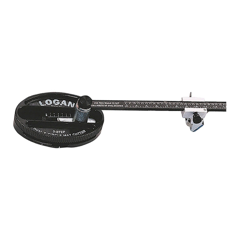
3-Step Oval and Circle Mat Cutter is easy to use, fast
and portable. Cuts ovals or circles on the surface of the
matboard using a patented 3-step mechanism for
gradual increase of blade depth.
Converts from oval to circle cutter with a turn of a
knob.
Oval from 31/4in. x 43/4in. to 20 in. x 23 in. Circles from
41/2in. to 20 in.
3-Step Oval & Circle Mat Cutter -
Model 201
Replacement Blades - Model 324
Simplex V-Groover offers a way to cut surface V-Grooves
quickly and accurately with zero overcuts.
Push-Pull action cuts V-Grooves right on the surface of the
matboard eliminating any need for trimming or taping.
Works entirely with stops.
Simplex V-Groover - Model 703
Replacement Blades - Model 1258
Secure artwork, backing board and glass into hard or
soft wood frames. Spring-loaded action drives both rigid
and flexible points. For successful operation, use only
authentic Logan points.
Dual-Drive Point Driver - Model F500-1
Replacement Points:
F53 - Flex Point Strip 600 pcs.
F54 - Rigid Point Strip 600 pcs.
F55 - Flex Point Strip 2,500 pcs.
F56 - Rigid Point Strip 2,500 pcs.
See your local Logan Dealer for availability or call at 800/331-6232 for a dealer near you, or please check our 'where to buy'
section on Logan's website www.logangraphic.com
Also available from Logan…
Take the guess work out of glass cutting simply by using
the Model 704 Glass Cutter with the Model 750 and
760 Simplex Plus mat cutters. The 704 mounts onto
the cutting rail in the same way as the standard straight
and bevel cutting heads supplied with the Simplex Plus,
providing quick and easy glass cutting.
Glass Cutter - Model 704

SIMPLEX PLUS
COUTEAUX À PASSE-PARTOUT MODÈLES 750 ET 760
CORTADOR DE LÁMINA PERIMÉTRICA MODELOS 750 Y 760
PASSEPARTOUTSCHNEIDER MODELLE 750 & 760
TAGLIERINE PER PASSEPARTOUT MODELLI 750 E 760
www.logangraphic.com
GAMME POUR PROFESSIONNELS • SERIE PROFESIONAL
PROFI-SERIE • SERIE PROFESSIONALE
Couteau à passe-partout Simplex Plus modèle 750 de 40 po (101,6 cm)
Couteau à passe-partout Simplex Plus modèle 760 de 60 po (152,4 cm)
MANUEL D'INSTRUCTIONS ET D’UTILISATION
Mat cutting system with laminate board, production stops, parallel
mat guide, 27" squaring arm, plus straight and bevel cutting heads
Cortador de lámina perimétrica de 40" - Modelo 750 Simplex Plus
Cortador de lámina perimétrica de 60" - Modelo 760 Simplex Plus
MANUAL DE INSTRUCCIÓN Y OPERACIÓN
Sistema de corte de la Lámina Perimétrica con tablero laminado,
topes de producción, guía paralela de la lámina perimétrica, brazo
de escuadra de 27", además de los cabezales de corte recto y
biselado
Modell 750 Simplex Plus – 100 cm Passepartout-Schneider
Modell 760 Simplex Plus – 150 cm Passepartout-Schneider
BEDIENUNGSANLEITUNG
Passepartout-Schneidesystem mit Laminatplatte,
Produktionsanschläge, paralleler Passepartout-Führung, 70 cm
Auswinkelarm sowie geraden und Winkel-Schneideköpfen.
Modello 750 Simplex Plus – Taglierina per passepartout 40"
Modello 760 Simplex Plus – Taglierina per passepartout 60"
MANUALE D'USO
Sistema di taglio per passepartout con pannello in laminato,
arresti di produzione, guida del passepartout parallela, braccio di
squadratura 27" e teste per tagli diritti e a smusso
FR
ESP
D
ITL
Para mejores resultados
utilice solamente las
cuchillas auténticas de Logan
Per ottenere i migliori risultati
usare solamente lame Logan
originali
Für optimale Schneidergebnisse
Verwendung von Logan-
Originalklingen empfohlen
Pour de meilleurs résultats
n’utilisez que les lames
Logan authentiques
Logan Graphic Products, Inc.
1100 Brown Street
Wauconda, IL 60084 USA
Phone (847) 526-5515
Fax (847) 526-5155
Toll Free (800) 331-6232
L759-N2 5/07
Date d'achat
Numéro d’identification (partie inférieure du support)
Date (partie inférieure du support)
Fecha de Compra
Número de identificación (en la parte baja del tablero)
Fecha (en la parte baja del tablero)
Kaufdatum
Kennnummer (an der Platte unten)
Datum (an der Platte unten)
Data di acquisto
Numero di identificazione (sul fondo del pannello)
Data (sul fondo del pannello)

Logan Graphic Products Inc., 1100 Brown Street, Wauconda, IL 60084 Toll Free 1 800 331 6232 www.logangraphic.com
1
SIMPLEX PLUS
COUTEAUX À PASSE-PARTOUT MODÈLES 750 ET 760
CORTADOR DE LÁMINA PERIMÉTRICA MODELOS 750 Y 760
PASSEPARTOUTSCHNEIDER MODELLE 750 & 760
TAGLIERINE PER PASSEPARTOUT MODELLI 750 E 760
Felicitaciones por su compra del Cortador de Lámina Perimétrica Simplex Plus de
Logan. El Simplex Plus es un cortador de la lámina perimétrica bien diseñado con
características profesionales para producir resultados profesionales. Características
tales como los topes de producción, la guía paralela de lámina perimétrica en canales
de aluminio y pasador anti-arrastre hacen del Simplex Plus una eficiente herramienta y
aún así efectiva por su costo, para los artistas, los fotógrafos y artesanos similares.
Este manual de instrucción se ha escrito para familiarizarlo a fondo con este producto.
Por favor tome un cierto tiempo para familiarizarse con el antes de cortar. Usted
encontrará que el tiempo será una buena inversión, y estará cortando láminas
perimétricas de calidad muy pronto.
INTRODUCCIÓN
Nous vous félicitons d’avoir acheté le couteau à passe-partout Logan Simplex Plus Le
Simplex Plus est un couteau à passe-partout de conception originale doté de
caractéristiques de type professionnel pour des résultats professionnels. Des dispositifs
comme les butées de production, le guide de passe-partout longitudinal en profilés
d’aluminium et goujon anti-glissement font du Simplex Plus un outil efficace et économique
pour les artistes, les photographes et les artisans. Ce manuel d’instructions a été conçu
pour vous permettre d’acquérir une connaissance approfondie de ce produit. Veuillez
prendre le temps de vous familiariser avec son contenu, avant de commencer à découper.
Vous verrez que le temps que vous aurez passé ne sera pas perdu, et que vous serez alors
très vite en mesure de découper des passe-partout de qualité.
INTRODUCTION
Congratulazioni per l’acquisto della vostra Taglierina per passepartout Simplex Plus
Logan! La Simplex Plus è una taglierina dal pratico design con caratteristiche
professionali per ottenere risultati professionali. Elementi come gli arresti di
produzione, la guida del passepartout parallela in canali di alluminio e il perno
antiscivolo rendono la Simplex Plus un utensile efficiente e al tempo stesso
vantaggioso per artisti, fotografi e artigiani. Il presente manuale d’uso intende fornirvi
le informazioni più complete possibili riguardo a questo prodotto. Si consiglia di
dedicare del tempo ad acquisire familiarità con il manuale prima di procedere con il
taglio. Scoprirete che ne sarà valsa la pena quando eseguirete tagli di qualità in
brevissimo tempo!
INTRODUZIONE
Wir gratulieren Ihnen zum Kauf Ihres Logan-Schneiders „Simplex Plus Mat Cutter“. Dieser
gut durchdachte, erschwingliche Schneider liefert Profi-Ergebnisse zu einem Bruchteil der
Kosten von Profigeräten. Eigenschaften, wie Produktionsanschläge, parallele
Passepartout-Führung in Aluminiumkanälen und ein Kriechschutzstift machen das Simplex
Plus zu einem effizienten und kostengünstigen Werkzeug für Künstler, Fotografen und
Heimwerker. Diese Bedienungsanleitung soll Ihnen den Umgang mit dem Werkzeug
erleichtern. Bitte lesen Sie sich vor dem Schneiden die Bedienungsanleitung gründlich
durch. Sie werden feststellen, dass Sie dann hochqualitative Passepartouts im
Handumdrehen zuschneiden können.
EINFÜHRUNG:

Logan Graphic Products Inc., 1100 Brown Street, Wauconda, IL 60084 Toll Free 1 800 331 6232 www.logangraphic.com
2
SIMPLEX PLUS
COUTEAUX À PASSE-PARTOUT MODÈLES 750 ET 760
CORTADOR DE LÁMINA PERIMÉTRICA MODELOS 750 Y 760
PASSEPARTOUTSCHNEIDER MODELLE 750 & 760
TAGLIERINE PER PASSEPARTOUT MODELLI 750 E 760
TABLE DES MATIÈRES:
Introduction 1
Description du produit 3
Identification des composants de l’appareil 3
Orientation
A. Déballage et vérification du contenu 4
B. Montage 4/5
C. Installation de la lame 5
Utilisation
A. Découpe à angle droit d’une feuille à la bonne dimension 6
B. Découpe d’une ouverture en biseau en utilisant les lignes de repère 6
C. Découpe d’une ouverture en biseau en n’utilisant qu’une butée de
production multiple 7
D. Découpe d’une ouverture en biseau en utilisant les deux butées de
production multiples 8
E. Découpe d’une ouverture à angle droit 9
Réglages et entretien
A. Ajustement de la hauteur de la lame 10
B. Repositionnement du guide longitudinal de passe-partout 11
C. Remise d’équerre du bras d’équerrage 11/12
D. Conseils utiles 13
Problèmes et solutions 14
Guide pour faire des passe-partout créatifs
A. Double passe-partout 15
B. Passe-partout à coins décalés 16
C. Passe-partout incrusté 17
ÍNDICE DE CONTENIDO:
Introducción 1
Descripción del producto: 3
Identificación de los Componentes de la Máquina 3
Orientación
A. Desempacando/comprobando el Contenido 4
B. Armado 4/5
C. Instalación de la Cuchilla 5
Operación
A. Corte Recto de Una Plancha A la Medida 6
B. Corte de una Abertura Biselada Utilizando Líneas Marcadas 6
C. Corte de una Abertura Biselada Utilizando Un Tope de Producción 7
D. Corte de una Abertura Biselada Utilizando Dos Topes de Producción 8
E. Corte de una Abertura Recta 9
Ajustes Y Mantenimiento
A. Ajuste De la Profundidad de la Cuchilla 10
B. Reponer en Paralelo la Guía de la Lámina Perimétrica 11
C. Re-poner a escuadra el Brazo de Escuadra 11/12
D. Datos Útiles 13
Solución de Fallas 14
Guía Creativa de Láminas Perimétricas
A. Lámina Perimétrica Doble 15
B. Lámina Perimétrica de Esquina Desplazada 16
C. Lámina Perimétrica de Embutir 17
INHALTSVERZEICHNIS:
Einführung 1
Produktbeschreibung 3
Geräteteile 3
Einweisung
A. Auspacken/Prüfen des Inhalts 4
B. Zusammenbau 4/5
C. Einlegen der Klingen 5
Bedienung
A. Gerades Zuschneiden eines Bogens 6
B. Schneiden einer winkligen Öffnung mit den markierten Linien 6
C. Schneiden einer winkligen Öffnung mit einem Produktionsanschlag 7
D. Schneiden einer winkligen Öffnung mit zwei Produktionsanschlägen 8
E. Schneiden einer geraden Öffnung 9
Einstellung & Wartung
A. Einstellung der Klingentiefe 10
B. ErneutesParallelisieren der Passepartout-Führung 11
C. Erneutes Glattstellen des Anwinkelarms 11/12
D. Hilfreiche Tipps 13
Fehlerbehebung 14
Kreative Schneidetechniken
A. Doppelte Passepartouts 15
B. Passepartouts mit versetzten Ecken 16
C. Einlege-Passepartouts 17
INDICE:
Introduzione 1
Descrizione del prodotto 3
Identificazione dei componenti 3
Orientamento
A. Disimballaggio/verifica del contenuto 4
B. Montaggio 4/5
C. Installazione della lama 5
Impiego
A. Taglio diritto a misura di un cartoncino 6
B. Taglio di un’apertura a smusso usando linee tracciate 6
C. Taglio di un’apertura a smusso usando un arresto di produzione 7
D. Taglio di un’apertura a smusso usando due arresti di produzione 8
E. Taglio di un'apertura diritta 9
Regolazioni e manutenzione
A. Regolazione della profondità della lama 10
B. Ripristino del parallelismo della guida del passepartout 11
C. Ripristino della squadratura del braccio di squadratura 11/12
D. Suggerimenti utili 13
Localizzazione guasti 14
Guida alla decorazione creativa del passepartout
A. Passepartout doppio 15
B. Passepartout con angoli inversi 16
C. Passepartout a intarsio 17
FR ESP
DITL

Logan Graphic Products Inc., 1100 Brown Street, Wauconda, IL 60084 Toll Free 1 800 331 6232 www.logangraphic.com
3
SIMPLEX PLUS
COUTEAUX À PASSE-PARTOUT MODÈLES 750 ET 760
CORTADOR DE LÁMINA PERIMÉTRICA MODELOS 750 Y 760
PASSEPARTOUTSCHNEIDER MODELLE 750 & 760
TAGLIERINE PER PASSEPARTOUT MODELLI 750 E 760
750 SimplexPlus - Tablero de Corte Laminado de 40" con la
Guía de la Lámina Perimétrica en canales de aluminio, dos topes
del carril de guía, Brazo de Escuadra de 27", Tope del Brazo de
Escuadra, Hoja de Respaldo, Cabezales de Corte Recto y Biselado,
el Destornillador Logan y 1 paquete de cinco cuchillas Logan
#270.
760 SimplexPlus -Tablero de Corte Laminado de 60" con la
Guía de la Lámina Perimétrica en canales de aluminio, dos topes
del carril de guía, Brazo de Escuadra de 27", Tope del Brazo de
Escuadra, Hoja de Respaldo, Cabezales de Corte Recto y Biselado,
el Destornillador Logan y 1 paquete de cinco cuchillas Logan
#270.
IDENTIFICATION DES COMPOSANTS DE L’APPAREIL
IDENTIFICACIÓN DE LOS COMPONENTES DE LA MÁQUINA
GERÄTETEILE
IDENTIFICAZIONE DEI COMPONENTI
Support de découpe Simplex Plus
Rail de guidage – sert à guider les têtes
de coupe pendant la découpe.
Guide de passe-partout – servent à fixer
la largeur de bordure d’un passe-partout
et maintenir le passe-partout en place.
Bras d’équerrage – barre montée à 90
degrés sur le support pour maintenir les
passe-partout d’équerre pendant la
découpe et comme butée pendant la
découpe de biseaux.
Support de découpe – support de
l’appareil en laminé.
Butées de production multiple – utilisées
pour les productions multiples afin
d’accélérer le processus de découpe des
passe-partout.
Feuille doublure – chute de feuille pour
passe-partout placée sous le passe-
partout à découper. Permet d’obtenir une
coupe plus franche ainsi qu’une durée de
vie des lames plus longue.
Butée du bras d’équerrage – utilisée
pour diminuer la surface de découpe du
support.
Tablero de Corte Simplex Plus
Barra Guía - Utilizada para guiar los
cabezales de corte mientras están en uso.
Guía de la Lámina Perimétrica - Utilizada
para ajustar la anchura de la franja de
lámina perimétrica y para mantener la
lámina perimétrica en posición.
Brazo de Escuadra - Barra de 90 grados
montada en un tablero de 27" utilizada
para sostener láminas perimétricas a
escuadra al cortar y como tope cuando se
corta a bisel.
Tablero de Corte - Tablero base de la
máquina, con la superficie laminada.
Topes de Producción - Utilizadas cuando se
hace corte de producción para acelerar el
proceso de corte de la lámina perimétrica.
Hoja de Respaldo - Pieza de desecho de
plancha de lámina perimétrica puesta
debajo de la lámina perimétrica que se
corta. Produce un corte más limpio y una
vida más larga de la cuchilla.
Tope del Brazo de Escuadra - Utilizada
cuando se achica la plancha de lámina
perimétrica.
Simplex Plus Schnittplatte
Führungsschiene- Zur Führung der
Schneideköpfe..
Passepartout-Führung- Bestimmung der
Randbreite eines Passepartouts und
Festhalten des Passepartouts.
Auswinkelarm- 70 cm lange, an der Platte
im 90° Winkel befestigte, Leiste zum
rechtwinkligen Festhalten des Passepartouts
beim Schneiden und als Anschlag beim
Winkelschnitt.
Schnittplatte- Laminatoberfläche der
Maschine.
Produktionsanschlag- Verwendung beim
Produktionschnitt, um das Schneiden von
Passepartouts zu beschleunigen.
Unterlagekarton – Extra-Passepartout, das
unter das zuzuschneidene Passepartout
gelegt wird, um die Qualität des
Winkelschnitts zu verbessern
Auswinkelarmanschlag- Zum Verkleinern des
Passepartoutkartons.
Pannello di taglio Simplex Plus
Rotaia di guida – Per guidare le teste di
taglio durante l’uso.
Guida per passepartout – Per definire la
larghezza del bordo di un passepartout e
tenere quest’ultimo in posizione.
Braccio di squadratura – Barra montata a
90 gradi sul pannello 27" usata per
mantenere i passepartout ad angolo retto
durante il taglio e come arresto durante il
taglio a smusso.
Pannello di taglio – Pannello di base
dell’attrezzo con superficie laminata.
Arresti di produzione – Utilizzati durante
il taglio di produzione per accelerare il
processo di taglio del passepartout.
Foglio di rinforzo – Pezzo di cartoncino
di scarto posizionato sotto il passepartout
da tagliare. Produce un taglio più netto e
allunga la durata della lama.
Arresto del braccio di squadratura –
Utilizzato per ridurre le dimensioni del
cartoncino.
Tête de découpe en biseau 702
Repère de début et de fin - Ligne
indicatrice du début et de la fin de la
découpe.
Vis de retenue – Vis qui permet de
maintenir la lame en toute sécurité dans
la fente quand elle est inutilisée.
Goujon anti-glissement – évite que la
tête de découpe de déraper vers l’avant
pendant l’entame de la lame dans le
passe-partout.
Guides de nylon - guides qui permettent à
la tête de découpe en biseaux de rester
au contact du rail de guidage.
Cabezal de Corte Biselado 702
Indicador de Comienzo y de Parada -
Línea que muestra donde comenzar y
terminar el corte.
Tornillo de Retención - Tornillo que
mantiene la cuchilla con seguridad dentro
de la ranura cuando no está en uso.
Pasador Anti-Arrastre - Evita que el
cabezal de corte se arrastre hacia
adelante durante la penetración inicial de
la cuchilla en la lámina perimétrica.
Guías de Nylon - Guías que permiten que
el Cabezal de Corte de Bisel se
enganchen en el Carril Guía
702 Winkelschneidekopf
Start- und Stopp-Anzeige – Linie, die
zeigt, wo der Schnitt anfängt und
aufhört.
Halteschraube – Schraube, die die Klinge
im Schlitz festhält, wenn diese nicht
verwendet wird.
Kriechschutzstift- Verhindert, dass der
Schneidekopf beim ersten Eindringen der
Klinge in das Passepartout nach vorne
kriecht.
Nylonführungen- Führungen, mit denen
sich der Winkelschneidekopf in die
Führungsschiene einhaken kann.
702 Testa per tagli a smusso
Indicatore di inizio e di fine – Linea che
mostra dove iniziare e dove terminare il
taglio.
Vite di fermo – Vite che tiene la lama
nella sua fessura in tutta sicurezza
quando non viene utilizzata.
Perno antiscivolo – Impedisce alla testa
di taglio di spostarsi in avanti durante
l’introduzione iniziale della lama nel
passepartout.
Guide di nylon – Guide che consentono
alla testa per tagli a smusso di
agganciarsi alla rotaia di guida.
Tête de découpe à angle droit 701
Support de la lame – vis de blocage qui
maintient la lame en place pendant la
découpe. Elle est dotée de trois réglages de
hauteur indépendants.
Plaque de couverture de la lame –
recouvre la lame dans son support.
Vis de serrage de la lame – maintient la
lame en place dans son support.
Cabezal de Corte Recto 701
Sujetador de la Cuchilla - Bloque que
retiene la cuchilla en su lugar mientras
corta. Tiene tres ajustes separados de
profundidad.
Cubierta de la Cuchilla - Cubre la cuchilla
sobre el Sujetador de la Cuchilla.
Tornillo de la Cuchilla - Retiene la
cuchilla en su lugar dentro del Sujetador
de la Cuchilla.
701 Gerader Schneidekopf
Klingenhalter – Block, der die Klinge beim
Schneiden festhält. Drei unterschiedliche
Tiefeneinstellungen.
Klingenschutz – Schutz der Klinge auf dem
Klingenhalter.
Klingenschraube – Hält die Klinge im
Klingenhalter fest.
701 Testa per tagli diritti
Portalama – Blocchetto che tiene ferma
la lama durante il taglio. Consente tre
regolazioni distinte di profondità.
Coprilama – Copre la lama montata sul
portalama.
Vite della lama – Tiene ferma la lama
nel portalama.
Rail de guidage
Carril Guía
Führungsschiene
Rotaia di guida
Guide de passe-partout
Guía de Lámina Perimétrica
Passepartout-Führung
Guida del passepartout
Support de découpe
Tablero de Corte
Schnittplatte
Pannello di taglio
Guides de nylon
Guías de Nylon
Nylonführungen
Guide di nylon
Repère de début et de fin
Indicador de Inicio y de Parada
Start- und Stopp-Anzeige
Indicatore di inizio e di fine
Vis de retenue
Tornillo de Retención
Halteschraube
Viti di fermo
Goujon anti-glissement
Pasador Anti-Arrastre
Kriechschutzstift
Perno antiscivolo
Support de lame
Sujetador de la Cuchilla
Klingenhalter
Portalama
Plaque de couverture de la lame
Cubierta de la Cuchilla
Klingenschutz
Coprilama
Vis de serrage de la lame
Tornillo de la Cuchilla
Klingenschraube
Vite della lama
DESCRIPCIÓN DEL PRODUCTO:
750 SimplexPlus -100 cm Laminat-Schnittpatte mit
Passepartout-Führung in Aluminiumkanälen, zwei
Führungsschienenanschlags, 70 cm Auswinkelarm,
Glattstellarmanschlag, Unterlagebogen, gerade und Winkel-
Schneideköpfe, Logan-Schraubenzieher und ein 5er Pack an Logan
#270 Klingen.
760 SimplexPlus -150 cm Laminat-Schnittpatte mit
Passepartout-Führung in Aluminiumkanälen, zwei
Führungsschienenanschlags, 70 cm Auswinkelarm,
Glattstellarmanschlag, Unterlagebogen, gerade und Winkel-
Schneideköpfe, Logan-Schraubenzieher und ein 5er Pack an Logan
#270 Klingen.
PRODUKTBESCHREIBUNG
750 SimplexPlus - Pannello di taglio laminato 40" con guida
del passepartout in canali di alluminio, due arresti per la rotaia di
guida, braccio di squadratura 27", arresto del braccio di
squadratura, foglio di rinforzo, teste per tagli diritti e a smusso,
cacciavite Logan e una confezione da cinque lame Logan #270.
760 SimplexPlus -Pannello di taglio laminato 60" con guida
del passepartout in canali di alluminio, due arresti per la rotaia di
guida, braccio di squadratura 27", arresto del braccio di
squadratura, foglio di rinforzo, teste per tagli diritti e a smusso,
cacciavite Logan e una confezione da cinque lame Logan #270.
DESCRIZIONE DEL PRODOTTO
Simplex Plus 750 - Support de découpe en laminé de 40 po
(101,6 cm) guide de passe-partout en profilés d’aluminium, deux
butées montées sur rail de guidage, bras d’équerrage de 27 po
(68,6 cm), butée de bras d’équerrage, feuille doublure, têtes de
découpe en biseau et à angle droit, tournevis Logan et un paquet
de cinq lames de rechange Logan n° 270.
Simplex Plus 760 -Support de découpe en laminé de 60 po
(152,4 cm) guide de passe-partout en profilés d’aluminium, deux
butées montées sur rail de guidage, bras d’équerrage de 27 po
(68,6 cm), butée de bras d’équerrage, feuille doublure, têtes de
découpe en biseau et à angle droit, tournevis Logan et un paquet
de cinq lames de rechange Logan n° 270.
DESCRIPTION DU PRODUIT
Butées de production multiple
Topes de Producción
Produktionsanschlag
Arresti di produzione
Bras d’équerrage de 27 po (68,6 cm)
Brazo de Escuadra de 27"
70 cm Auswinkelarm
Braccio di squadratura 27"
Feuille doublure
Hoja de Respaldo
Unterlagekarton
Foglio di rinforzo
Butée de bras d’équerrage
Tope del Brazo de Escuadra
Auswinkelarmanschlag
Arresto del braccio di squadratura

Logan Graphic Products Inc., 1100 Brown Street, Wauconda, IL 60084 Toll Free 1 800 331 6232 www.logangraphic.com
4
SIMPLEX PLUS
COUTEAUX À PASSE-PARTOUT MODÈLES 750 ET 760
CORTADOR DE LÁMINA PERIMÉTRICA MODELOS 750 Y 760
PASSEPARTOUTSCHNEIDER MODELLE 750 & 760
TAGLIERINE PER PASSEPARTOUT MODELLI 750 E 760
A. DÉBALLAGE ET VÉRIFICATION DU CONTENU
Les éléments emballés en vrac dans la boîte sont :
1. Tête de découpe à angle droit
2. Tête de découpe en biseau
3. Bras d’équerrage de 27 po (68,6 cm)
4. Guide de passe-partout
5. Guides en profilés d’aluminium (2)
6. Vis pour profilés (4)
7. Butées de rail de guidage (2)
8. Butée de bras d’équerrage (1)
9. Tournevis Logan
10. Paquet de cinq lames de rechange n° 270
11. Support de coupe n° 750 (non montré)
12. Feuille doublure (non montrée)
13. Manuel d’instructions (non montré)
A. DESEMPACANDO/COMPROBANDO EL CONTENIDO
Los artículos embalados sueltos en la caja incluyen:
1. Cabezal de Corte Recto
2. Cabezal de Corte Biselado
3. Brazo de Escuadra de 27"
4. Guía de Lámina Perimétrica
5. Canales de Guía de Aluminio (2)
6. Tornillos del Canal (4)
7. Topes del Carril Guía (2)
8. Tope del Brazo de Escuadra (1)
9. Destornillador Logan
10. Paquete de cinco cuchillas #270
11. Tablero base #750 (no mostrado)
12. Hoja de Respaldo (no mostrada)
13. Manual de Instrucción (no mostrado)
A. AUSPACKEN/PRÜFEN DES INHALTS
Lose Teile:
1. Gerader Schneidekopf
2. Winkelschneidekopf
3. 70 cm Auswinkelarm
4. Passepartout-Führung
5. Aluminium-Führungskanäle (2)
6. Kanalschrauben (4)
7. Führungsschienenanschläge (2)
8. Auswinkelarmanschlag (1)
9. Logan-Schraubenzieher
10. 5er Pack #270 Klingen
11. #750 Grundplatte (nicht abgebildet)
12. Unterlagekarton (nicht abgebildet)
13. Bedienungsanleitung (nicht abgebildet)
A. DISIMBALLAGGIO/VERIFICA DEL CONTENUTO
Ipezzi confezionati sciolti nella scatola comprendono:
1. Testa per tagli diritti
2. Testa per tagli a smusso
3. Braccio di squadratura 27"
4. Guida del passepartout
5. Canali di guida in alluminio (2)
6. Viti dei canali (4)
7. Arresti della rotaia di guida (2)
8. Arresto del braccio di squadratura (1)
9. Cacciavite Logan
10. Confezione da cinque lame #270
11. Pannello di base #750 (non illustrato)
12. Foglio di rinforzo (non illustrato)
13. Manuale d’istruzioni (non illustrato)
ORIENTATION
La procédure détaillée dans les instructions suivantes
se réfère au côté droit et gauche et à la partie
supérieure et inférieure de l’appareil ainsi qu’illustré.
Fig. 1
ORIENTACIÓN
El procedimiento detallado en las instrucciones
siguientes se refiere al lado derecho e izquierdo y a
la parte alta y la parte baja de la máquina según lo
mostrado. Fig. 1
EINWEISUNG
Das in der nachfolgenden Anleitung beschriebene
Verfahren bezieht sich auf die linke und rechte Seite,
sowie den oberen und unteren Teil der Maschine,
wie in der Abbildung zu sehen ist. Abb. 1
ORIENTAMENTO
La procedura descritta nelle seguenti istruzioni si
riferisce al lato destro e sinistro e alla parte
superiore e inferiore dell’attrezzo come illustrato.
Fig. 1
B. ARMADO
Guía de Lámina Perimétrica
1. Presione cada canal de aluminio de la guía de lámina perimétrica dentro de
las ranuras del tablero con el extremo redondeado hacia el Carril Guía.
Inserte los cuatro tornillos pequeños del canal del carril guía desde la
SUPERFICIE INFERIOR del tablero y apriete. Fig. 3
2. Para instalar al Guía de la Lámina Perimétrica afloje cada perilla tres vueltas
completas. Sostenga la guía de la lámina perimétrica en cualquiera de los
extremos y deje caer niveladamente la Guía de la Lámina Perimétrica dentro
de los canales de aluminio y apriete las perillas.
3. Para aflojar, gire las perillas en dirección contraria a las agujas del reloj y
deslice. Fig. 4
B : MONTAGE
Guide de passe-partout
1. Insérez chaque profilé en aluminium de guidage dans les fentes du support
avec les bords arrondis du côté du rail de guidage. Insérez les quatre petites
vis à profilé du rail de guidage à partir du dessous du support et serrez.
Fig. 3
2. Pour installer le guide de passe-partout, dévissez chaque bouton de trois tours
complets. Maintenez le guide de passe-partout à chaque bout, et insérez-le
de façon équilibrée dans les profilés en aluminium et serrez les boutons.
3. Pour desserrer, tournez les boutons dans le sens inverse des aiguilles d’une
montre et faites glisser. Fig. 4
B. MONTAGGIO
Guida del passepartout
1. Introdurre ciascun canale di guida del passepartout in alluminio nelle
scanalature del pannello con l'estremità arrotondata rivolta alla rotaia di
guida. Inserire le quattro piccole viti del canale della rotaia di guida dalla
PARTE INFERIORE del pannello e serrare. Fig. 3
2. Per installare la guida del passepartout allentare ciascuna manopola di tre giri
completi. Tenere la guida del passepartout per una delle estremità, inserirla
nei canali di alluminio e quindi serrare le manopole.
3. Per allentare, ruotare le manopole in senso antiorario e fare scorrere. Fig. 4
B. ZUAMMENBAU
Passepartout-Führung
1. Drücken Sie jeden Aluminium-Passepartout-Führungskanal in die
Plattenschlitze, wobei das abgerundete Ende zur Führungsschiene hin zeigt.
Stecken Sie die vier kleinen Führungsschienen-Kanalschrauben von der
UNTERSEITE der Platte ein und ziehen Sie sie fest. Abb. 3
2. Zum Einbau der Passepartout-Führung lösen Sie jeden Knopf um drei volle
Umdrehungen. Halten Sie die Passepartout-Führung an beiden Enden fest und
legen Sie die Passepartout-Führung in die Aluminumkanäle ein und ziehen
Sie die Knöpfe fest.
3. Zum Lösen drehen Sie die Knöpfe gegen den Uhrzeigersinn und schieben.
Abb. 4
Fig. 1
Fig. 3
Fig. 4
Partie supérieure
Arriba
Oben
Parte superiore
Côté droit
Derecha
Rechts
Destra
Côté gauche
Izquierda
Links
Sinistra
Partie inférieure
Abajo
Unten
Parte inferiore
Fig. 2
1.
2.
3. 4.
5.
6.
7.
8.
9.
10.

Logan Graphic Products Inc., 1100 Brown Street, Wauconda, IL 60084 Toll Free 1 800 331 6232 www.logangraphic.com
5
SIMPLEX PLUS
COUTEAUX À PASSE-PARTOUT MODÈLES 750 ET 760
CORTADOR DE LÁMINA PERIMÉTRICA MODELOS 750 Y 760
PASSEPARTOUTSCHNEIDER MODELLE 750 & 760
TAGLIERINE PER PASSEPARTOUT MODELLI 750 E 760
C. INSTALLATION DE LA LAME
Tête de découpe à angle droit 701
Retirez la vis de la lame et la plaque de couverture de la lame du support de lame. Placez une lame n° 270, le
bord tranchant vers le bas, dans la fente du support de lame et alignez le trou de la lame avec le réglage de
hauteur souhaité. Remettez en place la plaque de couverture de la lame et la vis de la lame. Fig. 4
Le n°701 offre trois réglages de hauteur différents :
Réglage haut – réglage de sécurité
Réglage moyen - feuille à passe-partout d’épaisseur normale (4 couches)
Réglage bas – planche de mousse de 3/16 po (0,48 cm)
REMARQUE : Ayez toujours les trois trous de la plaque de couverture de la lame
exactement alignés avec les trois trous du support de lame avant de remettre en place la
vis de la lame.
Tête de découpe en biseau 702
REMARQUE : La procédure suivante doit être suivie avant de desserrer le bouton de la
lame.
Desserrez la vis de retenue située sur le côté arrière de la tête de découpe jusqu’à ce qu’elle soit au même
niveau que la surface de la base. Ceci permet au support de lame de basculer en arrière entièrement, pour
remplacer la lame. Faites glisser une lame n° 270 à fond dans le support de lame tel qu’illustré. Fig. 5
REMARQUE : Le trou dans la lame, n’est pas destiné à s’aligner avec la vis de la lame.
Resserrez le bouton de la lame et basculez à nouveau en sens inverse le support de lame en permettant à la
pointe de la lame d’entrer dans la fente à lame. Resserrez la vis de retenue.
C. EINLEGEN DER KLINGE
701 Gerader Schneidekopf
Entfernen Sie die Klingenschraube und den Klingenschutz aus dem Klingenhalter. Legen Sie eine #270 Klinge
mit der scharfen Kante nach unten in den Schlitz auf dem Klingenhalter ein und richten Sie das Loch in der
Klinge mit der gewünschten Tiefeneinstellung aus. Bringen Sie den Klingenschutz und die Klingenschraube
wieder an. Abb. 4
#701 hat drei Tiefeneinstellungen:
Oberste Einstellung- Sicherheitseinstellung
Mittlere Einstellung- Standarddicke des Passepartoutkartons (4 Lagen)
Unterste Einstellung- 5 mm Schaumstoffplatte
HINWEIS: Die drei Löcher im Klingenschutz müssen immer genau mit den drei Löchern
auf dem Klingenhalter abgeglichen werden, bevor die Klingenschraube wieder
eingesteckt wird.
702 Winkel-Schneidekopf
HINWEIS: Das Folgende muss vor dem Lösen des Klingenknopfs vorgenommen werden.
Lösen Sie die Halteschraube an der Rückseite des Schneidekopfs, bis dieser auf gleicher Höhe wie die
Oberfläche der Grundplatte ist. Dadurch kann der Klingenhalter nach hinten gekippt werden, damit die Klinge
ausgewechselt werden kann. Schieben Sie eine #270 Klinge ganz nach hinten in den Klingenhalter, wie auf
der Abbildung zu sehen ist. Abb. 5
HINWEIS: Das Loch in der Klinge kann nicht mit der Klingenschraube abgeglichen werden.
Ziehen Sie den Klingenknopf wieder fest und biegen Sie den Klingenhalter nach unten, damit die Spitze der
Klinge in den Klingenschlitz eintreten kann. Ziehen Sie die Halteschraube wieder fest.
C. INSTALACIÓN DE LA CUCHILLA
Cabezal de Corte Recto 701
Quite el Tornillo de la Cuchilla y la Cubierta de la Cuchilla del Sujetador de la Cuchilla. Coloque una cuchilla
#270, borde afilado abajo, en la ranura del Sujetador de la Cuchilla y alinee el orificio en la cuchilla con el
ajuste deseado de profundidad. Vuelva a poner la Cubierta de la Cuchilla y el Tornillo de la Cuchilla. Fig. 4
El #701 tiene tres ajustes de profundidad:
Ajuste Superior - ajuste de seguridad
Ajuste Intermedio - tablero de lámina perimétrica de grosor estándar (4 capas)
Ajuste Inferior - lámina de espuma de 3/16"
NOTA: Tenga siempre los tres orificios en la Cubierta de la Cuchilla alineados
exactamente con los tres orificios en el Sujetador de la Cuchilla antes de volver a
poner el Tornillo de la Cuchilla.
Cabezal de Corte Biselado 702
NOTA: Lo siguiente debe hacerse antes de aflojar la perilla de la cuchilla.
Afloje el Tornillo de Retención que se encuentra en el lado posterior del Cabezal de Corte hasta que esté a
ras con la superficie de la base. Esto permite que el Sujetador de la Cuchilla se incline hacia atrás del todo
para hacer el cambio de la cuchilla. Deslice una cuchilla #270 hacia atrás hasta el fondo del Sujetador de la
Cuchilla según lo mostrado. Fig. 5
NOTA: El orificio en la cuchilla no está diseñado para alinearse con el Tornillo de la
Cuchilla.
Vuelva a apretar la Perilla de la Cuchilla e incline el Sujetador de la Cuchilla hacia abajo para permitir que la
punta de la cuchilla entre a la Ranura de la Cuchilla. Vuelva a apretar el Tornillo de Retención.
C. INSTALLAZIONE DELLA LAMA
701 Testa per tagli diritti
Rimuovere la vite della lama e il coprilama dal portalama. Inserire una lama #270, con il bordo affilato
rivolto verso il basso, nella fessura del portalama e allineare il foro della lama con la regolazione della
profondità desiderata. Sostituire il portalama e la vite della lama. Fig. 4
La #701 consente tre regolazioni di profondità:
Regolazione superiore – regolazione di sicurezza
Regolazione centrale – cartoncino di spessore standard (4 strati di
compensato)
Regolazione inferiore – foamboard 3/16"
NOTA: prima di sostituire la vite della lama, accertarsi che i tre fori del portalama
siano sempre esattamente allineati con i tre fori del portalama.
702 Testa per tagli a smusso
NOTA: prima di allentare la manopola della lama occorre sempre eseguire le seguenti
procedure.
Allentare la vite di fermo situata sul lato posteriore della testa di taglio finché non sia a livello con la
superficie della base. Ciò consente al portalama di inclinarsi all’indietro fino in fondo per sostituire la lama.
Far scorrere fino in fondo una lama #270 sul retro del portalama come illustrato. Fig. 5
NOTA: il foro nella lama non è stato ideato per allinearsi con la vite della lama.
Serrare nuovamente la manopola della lama e inclinare il portalama verso il basso facendo entrare la
punta della lama nell’apposita fessura. Serrare nuovamente la vite di fermo.
Fig. 4
Fig. 4
Fig. 5
BRAS D’ÉQUERRAGE
Utilisez l’outil d’alignement situé dans la fente du bras d’équerrage pour aligner la fente du
support avec celle du bras. Utilisez les deux grandes vis à métaux fournies pour fixer le bras
d’équerrage dans la fente du support. Ces vis à métaux sont vissées dans le support pendant
l’expédition. Fig. 4
FEUILLE DOUBLURE
Une feuille doublure est une chute de feuille de passe-partout placée sous le passe-partout à
découper pour la coupe en biseau. La feuille doublure doit être au moins aussi grande que le
passe-partout découpé et doit faire au minimum 4 po (10 cm) de large. Cela protège les lames
pendant la découpe et permet d’obtenir une meilleure découpe. Fig. 5
REMARQUE : Il est important de ne pas découper plusieurs fois au même endroit de la
feuille doublure, car cela peut causer des courbes dans la découpe. Remplacer la feuille
doublure si nécessaire.
BRAZO DE ESCUADRA
Utilice la herramienta de alinear que se encuentra en la ranura del brazo de escuadra para alinear
la ranura del tablero con la ranura en el brazo de escuadra. Utilice los dos tornillos de máquina
más grandes provistos para apretar el brazo de escuadra en la ranura del tablero. Estos tornillos
de máquina se encuentran enroscados en el tablero para los propósitos del viaje de envío. Fig. 4
HOJA DE RESPALDO
Una Hoja de Respaldo es una pieza de lámina perimétrica de desecho colocada debajo de la
lámina perimétrica que se cortará cuando se corta a bisel. La Hoja de Respaldo debe ser por lo
menos tan larga como la lámina perimétrica que se corta y por lo menos de 4" de ancho. Esto
protege las cuchillas mientras se corta y produce un corte mejor Fig. 5
NOTA: Es importante no continuar cortando en el mismo punto de la Hoja de Respaldo ya
que esto puede causar curvas en el corte. Reemplace la Hoja de Respaldo tanto como sea
necesario.
AUSWINKELARM
Verwenden Sie das Ausrichtwerkzeug im Auswinkelarmschlitz, um den Schlitz in der Platte mit
dem im Auswinkelarm auszurichten. Verwenden Sie die zwei größeren Maschinenschrauben, um
den Auswinkelarm im Plattenschlitz zu befestigen. Diese Maschinenschrauben werden zu
Transportzwecken in die Platte eingeschraubt. Abb. 4
UNTERLAGEKARTON
Ein Unterlagekarton ist ein Stück Abfall-Passepartoutkarton, der unter das Passepartout gelegt
wird, wenn Winkel geschnitten werden. Der Unterlagekarton muss mindestens so groß wie das
Passepartout sein und mindestens 10 cm breit. Damit wird die Klinge beim Schneiden geschützt
und Sie erhalten einen besseren Schnitt. Abb. 5
HINWEIS: Es ist wichtig, nicht immer an der selben Stelle des Unterlagekartons zu schneiden,
weil dadurch Kurven im Schnitt entstehen. Ersetzen Sie den Unterlagekarton regelmäßig.
BRACCIO DI SQUADRATURA
Utilizzare l’utensile di allineamento collocato nella scanalatura del braccio di squadratura per
allineare la scanalatura del pannello con la scanalatura del braccio di squadratura. Con le due viti
più grandi fornite, serrare il braccio di squadratura nella scanalatura del pannello. Queste viti si
trovano avvitate nel pannello per scopi di trasporto. Fig. 4
FOGLIO DI RINFORZO
Un foglio di rinforzo è un pezzo di cartoncino di scarto posizionato sotto il passepartout da
tagliare a smusso. Il foglio di rinforzo deve essere lungo almeno quanto il passepartout da
tagliare e largo almeno 4". In tal modo si proteggono le lame durante il taglio e si ottiene un
taglio migliore. Fig. 5
NOTA: è importante non continuare a tagliare nello stesso punto del foglio di rinforzo in
quanto ciò potrebbe causare curve nel taglio. Sostituire il foglio di rinforzo secondo
necessità.
Fig. 5
Outil d’alignement
Herramienta de Alinear
Ausrichtwerkzeug
Utensile di allineamento
Fig. 4
Feuille pour passe-partout
Plancha de Lámina Perimétrica
Passepartoutkarton
Cartoncino
Feuille doublure
Hoja de Respaldo
Unterlagekarton
Foglio di rinforzo
Fente à lame
Ranura de la Cuchilla
Klingenschlitz
Fessura della lama

SIMPLEX PLUS
COUTEAUX À PASSE-PARTOUT MODÈLES 750 ET 760
CORTADOR DE LÁMINA PERIMÉTRICA MODELOS 750 Y 760
PASSEPARTOUTSCHNEIDER MODELLE 750 & 760
TAGLIERINE PER PASSEPARTOUT MODELLI 750 E 760
Logan Graphic Products Inc., 1100 Brown Street, Wauconda, IL 60084 Toll Free 1 800 331 6232 www.logangraphic.com
6
B. DÉCOUPE D’UNE OUVERTURE EN BISEAU EN UTILISANT
LES LIGNES DE REPÈRE
EXEMPLE : Découpe d’un passe-partout avec une bordure de 2 pouces
(5,08 cm).
1. Pour installer à nouveau le guide de passe-partout longitudinal, desserrez les
boutons noirs de trois tours et, le bord relevé vers le rail de guidage, alignez le
guide de passe-partout avec les fentes parallèles. Maintenez le guide de passe-
partout à chaque extrémité et abaissez le dans les profilés en aluminium puis
serrez les boutons noirs.
2. Réglez le guide de passe-partout à la largeur de bordure souhaitée. Par
exemple, pour une bordure de 2 pouces (5,08 cm), alignez l’avant du guide
de passe-partout au niveau du repère de 2 pouces et serrez les boutons noirs.
Fig. 2
3. Assurez-vous que la feuille doublure est en place avant de procéder à une
découpe en biseau. Une feuille doublure est nécessaire. La fente de découpe à
angle droit sous le rail de guidage est uniquement réservée à la coupe à angle
droit.
4. Placez le passe-partout avec le côté coloré vers le bas, sous le rail de guidage et
contre le bras d’équerrage. Fig. 3
5. En utilisant un crayon, tracez une ligne sur toute la longueur au dos de la feuille
de carton. Répétez l’opération pour les trois autres côtés. Fig. 4
B. CORTE DE UNA ABERTURA BISELADA UTILIZANDO LÍNEAS
MARCADAS
EJEMPLO: Corte de una lámina perimétrica con una franja de 2".
1. Para reinstalar la Guía de la Lámina Perimétrica, afloje las Perillas Negras tres
vueltas y con el borde levantado hacia el Carril Guía, alinee la Guía de la Lámina
Perimétrica con las ranuras paralelas. Sostenga la Guía de la Lámina Perimétrica en
cualquier extremo y deje caer niveladamente la Guía de la Lámina Perimétrica
dentro de los canales de aluminio y después apriete las perillas negras.
2. Ajuste la Guía de la Lámina Perimétrica a la anchura de franja deseada. Por
ejemplo para una franja de 2" alinee el frente de la Guía de Lámina Perimétrica en
la marca de 2" y apriete las perillas negras. Fig. 2
3. Asegúrese de que la Hoja de Respaldo esté en su lugar antes de hacer el corte
biselado. Usted debe usar una Hoja de Respaldo. La ranura de corte recto debajo
del Carril Guía es usada para cortes rectos solamente.
4. Ponga el lado de color de la lámina perimétrica debajo del Carril Guía, contra la
Guía de la Lámina Perimétrica y abajo contra el Brazo de Escuadra. Fig. 3
5. Utilizando un lápiz, dibuje una línea de longitud completa del dorso de la lámina
perimétrica. Repita esto para los tres lados restantes. Fig. 4
B. SCHNEIDEN EINER WINKLIGEN ÖFFNUNG MIT
MARKIERTEN LINIEN
BEISPIEL: Schneiden eines Passepartouts mit einem 5 cm breiten Rand.
1. Zum Wiedereinbau der Passepartout-Führung lösen Sie die schwarzen Knöpfe
um drei Umdrehungen, damit die erhobene Kante zur Führungsschiene hinzeigt.
Richten Sie die Passepartout-Führung mit den parallelen Schlitzen aus. Halten
Sie die Passepartout-Führung an beiden Enden fest und legen Sie sie in die
Aluminiumkanäle ein. Ziehen Sie die schwarzen Knöpfe fest.
2. Stellen Sie die Passepartout-Führung auf die gewünschte Randbreite ein. Für
einen 5 cm breiten Rand richten Sie die Vorderseite der Passepartout-Führung
bei der 5 cm (2 Zoll) Markierung aus und ziehen die schwarzen Knöpfe fest.
Abb. 2
3. Vergewissern Sie sich, dass der Unterlagekarton vor einem Winkelschnitt
angebracht wurde. Sie müssen einen Unterlagekarton verwenden. Der gerade
Schnittschlitz unter der Führungsschiene kann nur für gerade Schnitte
verwendet werden.
4. Legen Sie das Passepartout mit der farbigen Seite nach unten unter die
Führungsschiene, an die Passepartout-Führung und an den Auswinkelarm.
Abb. 3
5. Ziehen Sie mit einem Bleistift Linien über die gesamte Länge der Passepartout-
Rückseite. Wiederholen Sie diesen Schritt für die anderen drei Seiten. Abb. 4
B. TAGLIO DI UN’APERTURA A SMUSSO USANDO LINEE
TRACCIATE
ESEMPIO: taglio di un passepartout con un bordo di 2".
1. Per reinstallare la guida del passepartout, allentare le manopole nere di tre giri e,
con il bordo sollevato verso la rotaia di guida, allineare la guida del passepartout
con le scanalature parallele. Tenere la guida del passepartout per una delle
estremità, inserirla uniformemente nei canali di alluminio e quindi serrare le
manopole nere.
2. Regolare i bordi della guida del passepartout in base alla profondità desiderata.
Ad esempio, per un bordo di 2" allineare la parte anteriore della guida del
passepartout sul segno 2" e serrare le manopole nere. Fig. 2
3. Prima di effettuare il taglio a smusso accertarsi che il foglio di rinforzo sia ben
posizionato. L’utilizzo di un foglio di rinforzo è necessario. La scanalatura diritta
sottostante la rotaia di guida serve esclusivamente per i tagli diritti.
4. Posizionare il lato colorato del passepartout sotto la rotaia di guida, contro la guida
del passepartout e in basso contro il braccio di squadratura. Fig. 3
5. Con una matita, tracciare una linea lungo l'intera lunghezza della parte posteriore
del cartoncino. Ripetere la procedura per i tre lati rimanenti. Fig. 4
OPERACIÓN
A. CORTE RECTO DE UNA PLANCHA A LA MEDIDA
1. Quite la Guía de la Lámina Perimétrica y la Hoja de Respaldo antes del corte recto.
2. Ajuste la Tope del Brazo de Escuadra en el número de la escala al cual usted quiere
cortar su lámina perimétrica.
3. Levante el Carril Guía y coloque una hoja de lámina perimétrica contra el Brazo de
Escuadra y deslice la plancha de lámina perimétrica a la derecha contra el tope.
Asegúrese de que esté en ángulo recto contra el Brazo de Escuadra.
4. Enganche el Cabezal de Corte Recto sobre el Carril Guía más allá del extremo del
tablero que se cortará. Agarre la manija según lo mostrado en el cuadro y tire del
cabezal de corte recto hacia usted. Mantenga la presión constante hacia abajo sobre
el Cabezal de Corte Recto y el Carril Guía conforme usted hace su corte Fig. 1
PRECAUCIÓN: Tenga cuidado de controlar el Cabezal de Corte Recto
conforme se abre paso a través del final de la lámina perimétrica, pues
tenderá a "saltar" hacia usted.
UTILISATION
A. Découpe à angle droit d’une feuille à la dimension voulue
1. Retirez le guide de passe-partout et la feuille doublure avant toute coupe à angle
droit.
2. Réglez la butée du bras d’équerrage sur le chiffre de la graduation correspondant
à la dimension de découpe souhaitée du passe-partout.
3. Levez le rail de guidage et placez une feuille à passe-partout contre le bras
d’équerrage et faites glisser la feuille vers la droite jusqu’à la butée. Assurez-vous
qu’elle est bien calée contre le bras d'équerrage.
4. Positionnez la tête de découpe à angle droit contre le rail de guidage au-delà du
bout de la feuille à découper. Saisissez la poignée comme illustré sur le croquis et
tirez la tête de découpe à angle droit vers vous. Maintenez une pression constante
sur la tête de découpe à angle droit et le rail de guidage pendant que vous
découpez. Fig. 1
ATTENTION : Soyez prudent de garder le contrôle de la tête de découpe
àangle droit quand elle arrive au bout de la feuille à passe-partout, car
elle aura tendance à « sauter » vers vous.
IMPIEGO
A. TAGLIO DIRITTO A MISURA DI UN CARTONCINO
1. Rimuovere la guida del passepartout e il foglio di rinforzo prima di effettuare il
taglio diritto.
2. Posizionare l’arresto del braccio di squadratura sul numero del righello a cui si
desidera tagliare il passepartout.
3. Sollevare la rotaia di guida, posizionare un foglio di cartoncino contro il braccio di
squadratura e far scorrere il cartoncino verso destra contro l’arresto. Accertarsi che
si trovi ad angolo retto contro il braccio di squadratura.
4. Agganciare la testa per tagli diritti alla rotaia di guida oltre l’estremità del pannello
da tagliare. Afferrare l’impugnatura come illustrato nella figura e tirare verso di sé
la testa per tagli diritti. Esercitare una costante pressione sulla testa per tagli diritti
e sulla rotaia di guida mentre si esegue il taglio. Fig. 1
CAUTELA: accertarsi di controllare la testa per tagli diritti mentre si
raggiunge la fine del cartoncino, in quanto tenderà a "saltare" verso di
voi.
BEDIENUNG
A. Gerades Zuschneiden eines Kartons
1. Entfernen Sie die Passepartout-Führung und den Unterlagekarton vor einem
geraden Schnitt.
2. Stellen Sie den Auswinkelarmanschlag auf die Zahl auf der Skala ein, auf die das
Passepartout zugeschnitten werden soll.
3. Heben Sie die Führungsschiene an und legen Sie einen Bogen Karton an den
Auswinkelarm. Schieben Sie den Passepartoutkarton rechts an den Anschlag.
Vergewissern Sie sich, dass er rechtwinklig am Auswinkelarm anliegt.
4. Haken Sie den geraden Schneidekopf auf der Führungsschiene über das Ende des
zuzuschneidenden Kartons hinaus ein. Halten Sie den Griff, wie in der Abbildung
gezeigt wird, und ziehen Sie den Geraden Schneidekopf zu sich hin. Üben Sie
konstanten Druck auf den Schneidekopf und die Führungsschiene aus, wenn Sie
Ihren Schnitt vornehmen. Abb. 1
ACHTUNG: Achten Sie darauf, den geraden Schneidekopf zu
kontrollieren, wenn der durch das Ende des Passepartoutkartons tritt,
weil er auf Sie „zuspringt“.
Fig. 1
Fig. 2
Butée de bras d’équerrage
Tope del Brazo de Escuadra
Auswinkelarmanschlag
Arresto del braccio di squadratura
2”
Fig. 3
Feuille pour passe-partout
Plancha de Lámina Perimétrica
Passepartoutkarton
Cartoncino
Feuille doublure
Hoja de Respaldo
Unterlagekarton
Foglio di rinforzo
Fig. 4

Logan Graphic Products Inc., 1100 Brown Street, Wauconda, IL 60084 Toll Free 1 800 331 6232 www.logangraphic.com
7
SIMPLEX PLUS
COUTEAUX À PASSE-PARTOUT MODÈLES 750 ET 760
CORTADOR DE LÁMINA PERIMÉTRICA MODELOS 750 Y 760
PASSEPARTOUTSCHNEIDER MODELLE 750 & 760
TAGLIERINE PER PASSEPARTOUT MODELLI 750 E 760
Fig. 5
Fig. 6
6. Placez le couteau biseauté 702 sur le rail de guidage.
7. Placez le couteau de sorte que le repère de début et de fin s’aligne avec la
ligne tracée la plus proche de la partie supérieure de l’appareil. Fig. 5
8. Avec la main gauche, appuyez sur le goujon anti-glissement et faites
pivoter fermement le support de lame dans la feuille. Fig. 5
9. Relâchez le goujon anti-glissement et tirez la tête de découpe vers vous
jusqu’à ce que le repère de début et de fin s’aligne avec la ligne tracée sur
la feuille à passe-partout la plus proche de vous. NE DÉPASSEZ PAS CETTE
LIGNE ! Fig. 6
REMARQUE : Il est essentiel de maintenir une pression d’appui
sur le support de lame lors de la coupe.
10. Faites pivoter le support de lame en position neutre, tournez le passe-
partout de 1/4 de tour vers la droite et répétez les étapes 7 à 9 pour les
trois côtés restants afin de terminer le passe-partout.
6. Enganche el Cortador de Bisel 702 en el Carril Guía.
7. Coloque el cortador de modo que la línea Indicadora de Inicio y de Parada se
alinee con la línea marcada lo más cercana posible a la parte alta de la
máquina. Fig. 5
8. Presione hacia abajo con la mano izquierda el Pasador Anti-Arrastre y gire
firmemente el Sujetador de la Cuchilla abajo dentro de la lámina perimétrica.
Fig. 5
9. Libere el Pasador Anti-Arrastre y tire del cabezal del corte hacia usted hasta
que la línea Indicadora de Inicio y Parada se alinee con la línea en la lámina
perimétrica más cercana a usted. ¡NO VAYA MÁS ALLÁ DE LA LÍNEA! Fig. 6
NOTA: Es esencial mantener la presión hacia abajo estable sobre el
Sujetador de la Cuchilla conforme usted corta.
10. Rote de vuelta el Sujetador de la Cuchilla hasta la posición neutral, gire la
lámina perimétrica 1/4 de vuelta a la derecha y repita los pasos 7 a 9 para
los tres lados restantes para terminar la lámina perimétrica.
6. Haken Sie den 702 Winkelschneider in die Führungsschiene ein.
7. Positionieren Sie den Schneider so, dass die Start- und Stopp-Anzeigelinie
mit den markierten Linien oben auf der Maschine ausgerichtet sind. Abb.
5
8. Drücken Sie mit der linken Hand den Kriechschutzstift und drehen Sie den
Klingenhalter fest nach unten in das Passepartout. Abb. 5
9. Lassen Sie den Kriechschutzstift los und ziehen Sie den Schneidekopf zu
sich hin, bis die Start- und Stopp-Anzeigelinie mit der Ihnen am nächsten
liegenden Linie auf dem Passepartoutkarton. GEHEN SIE NICHT ÜBER
DIESE LINIE HINAUS! Abb. 6
HINWEIS: Es ist wichtig, dass Sie beim Schneiden Druck auf den
Klingenhalter ausüben.
10. Drehen Sie den Klingenhalter nach oben in die neutrale Position und
drehen Sie das Passepartout um _ Drehung nach rechts. Wiederholen Sie
die Schritte 7 bis 9 für die restlichen drei Seiten, um das Passepartout
fertigzustellen.
6. Agganciare la taglierina per passepartout a smusso 702 alla rotaia di guida.
7. Posizionare la taglierina in modo tale che l’indicatore di inizio e di fine si
allinei con la linea tracciata più vicina alla cima dell’attrezzo. Fig. 5
8. Con la mano sinistra premere il perno antiscivolo e inserire il portalama nel
passepartout ruotandolo verso il basso. Fig. 5
9. Rilasciare il perno antiscivolo e tirare la testa di taglio verso di voi finché
l’indicatore di inizio e di fine non si allinei con la linea sul cartoncino più vicina
a voi. NON SUPERARE LA LINEA! Fig. 6
NOTA: è essenziale esercitare una pressione uniforme sul portalama.
10. Ruotare nuovamente il portalama riportandolo in posizione neutrale, ruotare il
passepartout di 1/4 di giro verso destra e ripetere le procedure da 7 a 9 per i
tre lati rimanenti per terminare il passepartout.
Fig. 2
C. DÉCOUPE D’UNE OUVERTURE EN BISEAU EN
N’UTILISANT QU’UNE BUTÉE DE PRODUCTION
MULTIPLE
EXEMPLE : Découpe d’un passe-partout avec une bordure de 2
pouces (5,08 cm).
1. Réglez le guide de passe-partout à la largeur de bordure souhaitée. Par
exemple, pour une bordure de 2 pouces (5,08 cm), alignez l’avant du
guide de passe-partout au niveau du repère de 2 pouces et serrez les
boutons noirs. Fig. 1
2. Placez le passe-partout à découper dans l’appareil, le côté coloré vers le
bas, avec la feuille doublure en dessous et abaissez le rail de guidage.
3. Placez la butée du rail de guidage au repère 2 po (5,08 cm) sur l’échelle
graduée et serrez. Fig. 2
suite page 8
2”
Fig. 1
2”
C. CORTE DE UNA ABERTURA BISELADA UTILIZANDO UN
TOPE DE PRODUCCIÓN
EJEMPLO: Corte de una lámina perimétrica con una franja de 2".
1. Ajuste la Guía de la Lámina Perimétrica a la anchura de franja deseada. Por
ejemplo para una franja de 2" alinee el frente de la Guía de Lámina
Perimétrica en la marca de 2" y apriete las Perillas Negras. Fig. 1
2. Coloque la lámina perimétrica que se cortará dentro de la máquina con el lado
de color hacia abajo y con la hoja de respaldo debajo y baje el carril guía.
3. Instale el tope del carril de guía sobre el carril de guía y apriete en la marca de
2"en la escala. Fig. 2
Continúa en la página 8
C. SCHNEIDEN EINER WINKLIGEN ÖFFNUNG MIT
EINEM PRODUKTIONSANSCHLAG
BEISPIEL: Schneiden eines Passepartouts mit einem 5 cm
breiten Rand.
1. Stellen Sie die Passepartout-Führung auf die gewünschte Randbreite ein.
Für einen 5 cm breiten Rand richten Sie die Vorderseite der
Passepartout-Führung mit der 5 cm (2 Zoll) Markierung aus und ziehen
die schwarzen Knöpfe fest. Abb. 1
2. Legen Sie das zuzuschneidende Passepartout mit der farbigen Seite
nach unten mit dem Unterlagekarton in die Maschine und senken Sie
die Führungsschiene.
3. Installieren Sie den Führungsschienenanschlag auf der Führungsschiene
und ziehen Sie bei 5 cm (2 Zoll) auf der Skala fest. Abb. 2
Fortsetzung auf Seite 8
C. TAGLIO DI UN’APERTURA A SMUSSO USANDO UN
ARRESTO DI PRODUZIONE
ESEMPIO: taglio di un passepartout con un bordo di 2”.
1. Regolare i bordi della guida del passepartout in base alla profondità desiderata.
Ad esempio, per un bordo di 2" allineare la parte anteriore della guida del
passepartout sul segno 2" e serrare le manopole nere. Fig. 1
2. Posizionare il passepartout da tagliare nell’attrezzo con il lato colorato rivolto
verso il basso e con il foglio di rinforzo sotto di esso, e abbassare la rotaia di
guida.
3. Installare l'arresto della rotaia di guida sulla rotaia stessa e serrare sul segno
2” del righello. Fig. 2
Continua a pagina 8
This manual suits for next models
1
Table of contents
Other Logan Cutter manuals

Logan
Logan 525 User manual

Logan
Logan FoamWerks W3002 User manual

Logan
Logan 250 User manual

Logan
Logan Fit-N-Frame Border Guide 262 User manual

Logan
Logan 201 Manual

Logan
Logan 301-S Manual

Logan
Logan Compact Classic 301-1 User manual

Logan
Logan Team System Plus 440-1 User manual

Logan
Logan 750-1 Manual

Logan
Logan PICTURE FRAMING F503 User manual
Popular Cutter manuals by other brands

FangLing
FangLing F2100B/T Operation and installation manual

Land Pride
Land Pride RC5020 Series Operator's manual

Land Pride
Land Pride RCR1860 Series Operator's manual

DeWalt
DeWalt DCS350 instructions

Erbauer
Erbauer ERB337TCB Safety and operating manual

Cembre
Cembre B35M-TC025 Operation and maintenance manual