Vivid Veloblade Volta User manual

0
Introduction User
Manual for

1
Contents
Page 2-3: Chapter 1 –Machine set up
Page 4-5: Chapter 2 –Tools and their positions
Page 6-10 : Chapter 3 –Tool settings & Test Depth
Page 11-15: Chapter 4 –Software lay-out
Page 16: Chapter 5 –Importing files
Page 17-20: Chapter 6 –Software modes
Page 21: Chapter 7 –Blade changing
Page 22-24 : Chapter 8 –Maintenance

2
1.Machine set up
Power on the machine, ensure all switches are in the up position [figure 1.1]
Open the Veloblade software [figure 1.2]
If the feeder is needed please load the media onto the feed table. [figure 1.3]
Ensure the media has movement and the magnetic back stop and side lays are
not too tight. The position of the magnetic sides are important., these cannot
be past the red line shown in figure 3. The red line represents where the
movement of the feed head moves to pick up a sheet.
Figure 1.1
Figure 1. 2
Figure 1.3

3
Once the material is loaded into the feeder press the green button and feed
table will move into position and the lights will illuminate [Figure 1.4].
If you require a roll of material cutting, remove all media from the feed table,
load the material onto the mandrel, put in the mandrel brackets and place the
idle bar in position [Figure 1.5]. Now thread the material around the idle bar
and place onto the cutting bed [Figure 1.6].
Figure 1.4
Figure 1.5
Figure 1.6

4
2. Tools and their positions
The tools used on the Veloblade Volta and their positions on the machine [see
figure 2.1 below for positions]:
Position 1
•PCTT –Crease tool
Position 2
•RCT –Rotary cutting tool [for materials up to 2mm]
Position 3
•PRCT –Pen tool
•RCT –Rotary cutting tool [in this position we use the RCT for kiss cutting]
1
2
3
Figure 2.1

5
RCT/PRCT:
Remove the locking the screw and cap [Figure 2.2] and place the tool in the
holder. Ensure the tool is pushed all the way into the holder to the lip on the
tool [Figure 2.3] and reattach the locking screw and cap.
For blade changing please see chapter 7.
PCTT:
To remove the crease tool pull down on the crease wheel [figure 2.4 & 2.5], to
reinsert place the wheel into the slots and push upwards [figure 2.6].
Figure 2.2
Figure 2.3
Figure 2.4
Figure 2.5
Figure 2.6

6
3. Tool settings & Test depth
Switch the window to Debug View and select the tool position you want to set
[Figure 3.1].
Move the head [using the arrow keys on the keyboard] over your test material
ensuring the tool you are setting is located above the material and press T-
depth [Figure 3.2].
Turn off the Vacuum [Vac1] and move the head out of way using the arrows on
the keyboard. Inspect the test cut, Ensure it is a clean cut all the way through
the media. Too much blade will leave a rough cut and raised edges and not
enough will not cut all the way through the media.
For other [i.e. speed] adjustments click on Cutting tool configuration near the
top of the screen [Figure3.3].
Figure 3.1
Figure 3.3
Figure 3.2

7
Select the tool position for the tool you want to change the speed for, alter to
the desired speed [figure 3.4]. For creasing, if the speed is to high it can cause
cracking on coated stocks.
Click save and close the window.
PRCT/RCT:
Changing the depth of the blade on these tools is done manually.
Remove the tool from its tool position, loosen the brass locking nut [Figure 3.8]
and turn the top knurled knob for more or less blade [Figure3.9].
Figure 3.4
Figure 3.8
Figure 3.9

8
Too much blade showing and it will leave a rough cut. To get the correct
amount of blade for a through cut hold the material you wish to cut at the end
of tool holder near the blade [Figure 3.10] and adjust the blade to the required
depth.
For Kiss cutting on materials [i.e. crackback, vinyl] the blade depth needs to be
minimal, see the difference between figure 3.11 [Set for through cut] and
figure 3.12 [set for kiss cutting].
Manually test the tool to check if the blade is at the correct height, hold the
tool firmly and straight, While applying a substantial amount of pressure draw
Figure 3.10
Figure 3.11
Figure 3.12
Figure 3.13

9
a circle on test material [this must be done on the belt of the machine] see
figure 3.13.
Once the blade is set and manually tested, return the tool to its position on the
machine and secure. The next step is to do a test cut, place a piece of scrap
material onto the belt, move the head into position over the media and press
T-depth in the Debug View window.
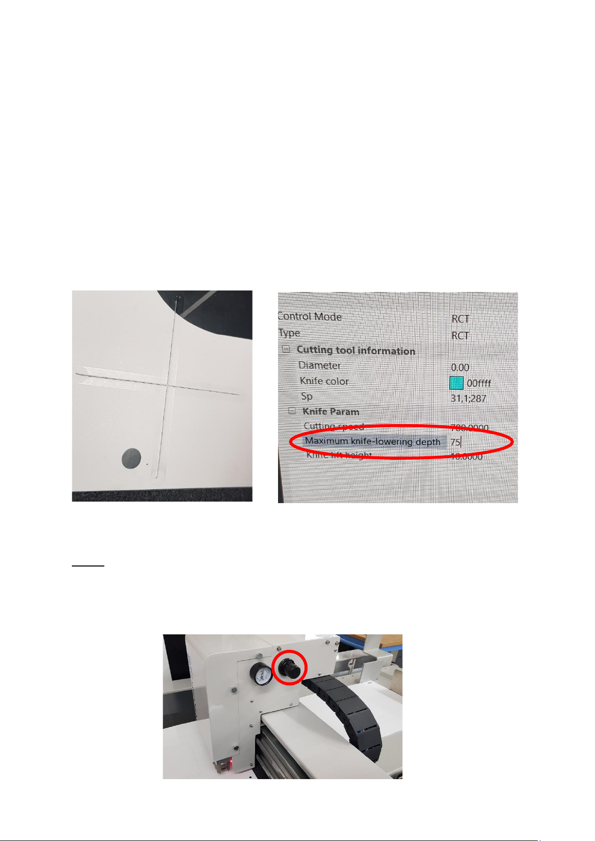
If you’re getting marking from the tool holder on the media [Figure 3.14] or the
tool is not making contact with the media, You will need to change the
pressure of the tool solenoid, Click on Cutting Tool Configuration, select the
number of the tool you are using [3 or 4], change the maximum knife lowering
depth.
Decreasing the number will apply less pressure.
PCTT:
There are two ways to adjust the amount of pressure on the crease wheel, the
first is to adjust the valve and allow more or less air pressure [Figure 3.16].
Anticlockwise will reduce the amount of air pressure.
Figure 3.14
Figure 3.15
Figure 3.16

10
The second way to adjust the crease pressure is a mechanical setting. Remove
the head cover as shown in figure 3.17 by loosening the 3 silver knurled knobs
on either side of the head.
Once removed, you will require a 22mm and 17mm spanner [these have been
provided with the machine]. Place the 22mm spanner on the Crease solenoid
[figure 3.18] and the 17mm spanner on the locking nut [figure 3.19].
Once the locking nut is loose, turn the solenoid shaft anticlockwise to lower
the crease wheel or clockwise to higher. When you are at your desired height
tighten the locking nut and return the head cover.
Figure 3.17
Figure 3.18
Figure 3.19

11
4. Software layout & Editing files
Software layout:
Switch Button –to switch between CCD window and Debug view [Figure 4.1]
CCD Window is used to select the mode you require and mainly for Camera
operation [Roll CCD and Board CCD]. See figure 4.2.
Debug View is used for manual controls, choosing the tools to use, test depth
[t-depth] and blade depth. See figure 4.3
Figure 4.1
Figure 4.2
Manual button for Vacuum
Figure 4.3
Lowers the suction cups for
the alignment of media
Manual feed button
Test Cut

12
At the bottom of the screen is the Output window [Figure 4.4], this gives the
information of any errors, if the machine is in run/pause mode and or if the
emergency stop buttons are pressed.
The Historic tasks button on the top left of the screen [Figure 4.5], saves
previous cut files that have been used. When restoring a file, right click the file
and press restore. Please note these files cannot be edited and can only be
used in Direct cut mode.
Figure 4.4
Figure 4.5

13
Editing:
Click the edit button in the top middle of the screen [Figure4.6].
Advanced button: Top left of the window [Figure 4.7], in this section we have
tick boxes for various requirements, for example click the directional line
showing and it will place an arrow on the artwork showing the direction of cut.
Another example, Coordinate point showing when selected will show each
node/point on the artwork.
Start window: Using the mouse you can zoom in and out of the artwork to
check if lines are joined, to move the artwork up/down/left/right.
Move view [Figure 4.8]: Once selected you can move the artwork with the
mouse.
Integrated pick up: Once selected you can delete, move and add extra
nodes/points [Right click on any part of the artwork]. To move a selection of
lines, press and hold the left mouse button and highlight the area you require.
Figure 4.6
Figure 4.7
Figure 4.8

14
Rotate button [Figure 4.9]: When selected, highlight the artwork/lines you
wish to rotate and right click on the mouse [Figure 4.10].
To the right of the screen we have the Property window, from here we can
change the tool, stepping [half cutting or step cutting] and dash/perforated
lines. Please note the artwork you are changing must be highlighted.
Highlight the line you want to change and use the drop down menu next to:
•Changing the tool used - Knife [Figure 4.11].
•Change a solid line to a Dash/Perforated line –Cutting Line [Figure 4.12].
Figure 4.9
Figure 4.10
Figure 4.11
Figure 4.12

15
•Stepping [Figure 4.13 on next page]:
oMaterial -Material thickness.
oCutting - Cutting depth, i.e. half cut for a 10mm board would be
set at 5mm or through cut would be set at 10mm.
oStep Value –the depth you want to cut each cycle, i.e. for a 10mm
board and you select 2.5 as a step value it will cut 4 times.
Figure 4.13

16
5.Importing files
Before importing a file please ensure you are in the correct mode, i.e. Board
CCD, Roll CCD or Direct Cut these are explained on the next page.
Click Import file and select the artwork required [Figure 5.1].
Once selected you will need to choose which tools are needed for which cut
lines [Figure 5.2]. Select the drop down for each colour and select the tool
needed [Figure 5.3].
when finished click ok.
Figure 5.1
Figure 5.2
Figure 5.3

17
6.Software Modes
•Board CCD –Printed material with registration marks
•Roll CCD –Printed rolls of material with registration marks
•Direct Cut –Material without registration marks.
Board CCD: Switch the Window to CCD Window and select Board CDD from the
drop down mode. Select how many sheets you require cutting and press apply
[Figure 6.1].
Switch the window into Debug view and press feed [Figure 6.2]
Import the artwork for cutting.
Ensure the artwork is matches the direction on the screen [Figure 6.2] .Rotate
the artwork if needed [Figure 6.3].
Select Mode
How much material
needs cutting
Apply
Start
Figure 6.1
This is the front of the
feeder closest to the belt
and is the direction it feeds.
Figure 6.2

18
Figure 6.4
Using the arrow keys on the keyboard move the camera over the first
registration mark numbered 1 on the screen, see Figure 3.9 bottom left corner.
Once in position, press the switch button and press start in the CCD window.
Roll CCD: Select Roll CDD from the drop down mode in CCD Window [Figure
6.4], Select how many you’ve printed that require cutting [times], enter the
page length [printed area of cut file] and input the gap [printed distance
between the registration marks, minimum is 40mm. see Figure 6.5] and click
apply.
Figure 6.3
Figure 6.5

19
Thread the printed media onto the belt under the idle bar, ensure the media is
straight to the edge of the belt and turn on the Vacuum [Vac1].
Import the cut file required, ensure the artwork matches the direction on the
screen.
Using the arrow keys on the keyboard move the camera over the first
registration mark numbered 1 on the screen.
Once in position, press start in the CCD window.
Direct Cut: Select Direct Cut from the drop down mode in CCD Window and
switch the window.
Load the media into the feeder, press the red button to raise the feed table
and press feed in the Debug View [if using heavy large material manually place
onto the belt].
Import the cut file required, ensure the artwork matches the direction on the
screen. If the artwork doesn’t match and you cant turn the media around on
the belt you will need to go into Edit and rotate the cut file.
Using the arrow keys on the keyboard move the laser to just inside corner of
the media as shown in figure 6.6.
In Debug window click on temporary origin [Figure 6.7], a window will open
asking ‘Whether to set origin’, click yes.
Figure 6.6
Figure 6.7
Table of contents
Other Vivid Cutter manuals