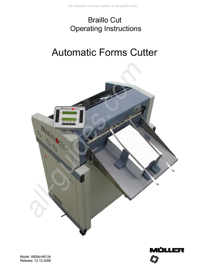
Muller 6609d Operating instructions

Service Instructions
AutomaticFormsCutter
Modell 6609d-6612d
Stand:31.05.2006

Mod. 6609-12d: Automatic FormsCutter31.05.2006
2
Contents
Toollist................................................................................3
EG-Konformitätserklärung..................................................................4
Subassemblies..........................................................................5
1.Adjusting tractor shaft.................................................................6
2.Removing the sprocket beltsofthe tractors.................................................6
3.Tightening the sprocket belts............................................................7
4.Removing the plate cover on the tractor...................................................7
5.Adjusting the magnetic hall-sensor on the plexiglass cover.....................................7
6.Adjusting the pneumatic spring on the plexiglass cover........................................7
7.Adjusting the paper guide (on the pneumatic spring)..........................................8
8.Adjusting the fibre-optic sensor for determining paper end......................................8
9.Removing the tractor shaft..............................................................8
10.Removing scannerson the tractor and cross cutter...........................................9
11.Cleaning, installing and adjusting scannerson the tractor shaft.................................10
12.Cleaning, installing and adjusting scannerson the cross cutter.................................10
13.Removing the cross cutter.............................................................11
14.Removing and adjusting the cross cutter blade.............................................12
15.Adjusting spring pressure ofthe lower blade on the cross cutter.................................13
16.Removing the blade bar...............................................................13
17.Removing and adjusting the blade guide bar...............................................14
18.checking and adjusting the angle ofthe cross cutter.........................................14
19.Removing the driving gear on the cross cutter..............................................15
20.Removing the deflector cylinder and ejector cylinders........................................15
21.Removing the ejector and deflector......................................................15
22.Removing the bladesofthe edge cutters..................................................16
23.Removing the terminalboard and replacing the eprom.......................................17
24.Replacing the fuse..................................................................17
25.Changing the mainsvoltage...........................................................17
26.Main PC-Board connections............................................................18
27.Removing the main board ............................................................18
Main PC-Board installation................................................................19
Listing ofall Automatic FormsCutter PCB, being produced since 1988...............................20
Measurement-Points-PC-Board..........................................................21/22
OMR.................................................................................23

Mod. 6609-12d: Automatic FormsCutter31.05.2006
3
Tool list
A toolcase isavailable which containsall the toolslisted below:
Part no.Decription SizeNo. each
10580Cable tie 3
10893*Pin (for installing the pulley ofthe cross cutter)1
10897Feeler gauge61
10899*Open-ended spanner121
10961*Toolfor adjusting tractor shaft2
11077*Tachometer generator, complete1
11096*Holder complete for measuring unit1
11099*Measuring device for dialindicator 1
11101*Adjusting toolfor mounting cross cutter2
11102*Dialindicator 5/401
11103Plastic hammer221
11104Open-end ring wrench 101
11105Socket spanner101
11106Hexagon screwdriver with T-handle51
11107Open-end wrench5,51
11110Screwdriver for Philipsscrews21
11111Screwdriver for Philipsscrews11
11112*Plastic oiler11
11113Externalsnap ring pliersA01
11114Screwdriver3,5 x901
11115Screwdriver5,5 x2501
11116Open-end wrench71
11117Hexagon offset screwdriver31
11119*Magnet1
11121*High-speed grease1
11122*Triboelectric grease1
11123*Thermaltransfer compound1
11124Cable tie20
11158Toolcase1
11167*Adjusting toolfor potentiometer 1
12678Hexagon offset screwdriver51
13119Hexagon ball-head screwdriver31
13572*Lever (to change knives)1
14130Bit handle equipped with2
14131Bit (head 4 mm) for hexagon socket 21
14132Bit (head 4 mm) for hexagon socket 1,51
15336*Lever (to remove hexagon shaft) 1
15368Hexagon offset screwdriver2,51
15369Bit (head 4 mm) for hexagon socket 2,51
15667*Extension cord (for cross cutter motor) 2
15729*Holder complete for measuring unit1
15731*Measuring device for dialindicator 1
17597Brush2
17688*Extension cord (for cross cutter motor) 40 cm1
18182Open-ended ring spanner71
18853Hexagon screwdriver with T-handle41
19574Hexagon offset screwdriver81
21317Hexagon socket key with long handle1
23872Bit handle equipped with1/4"2
24939Bit (head 1/4" mm) for hexagon socket 2,51
24940Bit (head 1/4" mm) for hexagon socket 3,01
29890Hexagon offset screwdriver1,51
29891Hexagon offset screwdriver21
29892Hexagon offset screwdriver41
35211 Bit (head 1/4") for TorxTX10 1
35212 Bit (head 4mm) for TorxTX10 1
35286 TorxOffset Screwdriver TX10 1
29894Order-no. for hexagon screwdriver set complete consisting ofno.:1
11117, 12678, 14130 (2x), 14131, 14132, 23872 (2x), 24939, 24940,
29890, 29891, 29892
13570Order-no. for toolcase complete1
* Müller special tool
Release: 31.05.2006

Mod. 6609-12d: Automatic FormsCutter31.05.2006
4

Mod. 6609-12d: Automatic FormsCutter31.05.2006
5
Subassemblies
Housing and cover sheets
Frame
Driving shafts
Frame - motorsand fan
Safety cover
Cross cutter - blade bar
Cross cutter - ejector
Cross cutter - drive
Tractor unit
Tractor right and left
Edge cutter unit
Edge cutter right and left
Terminal
Power switch unit
Electronic and optoelectronic systems

Mod. 6609-12d: Automatic FormsCutter31.05.2006
6
Caution: When performing servicing work on the cutter, alwaysmake sure it
isdisconnected fromthe mainspower supply.
1. Adjustingtractorshaft
The tractor shaft isdivided in the middle.
Usethe twoadjusting tools(toolno. 10961) to rotate the
tractor shaft and adjust the angle ofthe cross cutter.
2. Removingthe sprocket belts of the tractors
Remove the tractor shaft asdescribed in 9.
Removelower paper guide .Press the plate inthe
direction ofthe arrowand removethe tie-bar and tractor.
Unscrewand take off the cover plate .
Removethe sprocket belt. When re-installing the sprocket
belts,make sure that the gear teethofthe left and right
tractorsareinthe sameposition with regard to the hexagon
socket ofthe toothed gear.
Thisiseasier, ifyou firstposition thesprocket belton the
toothed gear .

Mod. 6609-12d: Automatic FormsCutter31.05.2006
7
3.Tighteningthe sprocket belts
Tightening the sprocket beltsisdone by pushing the rear cap
bolt. To do so, firsttake off the cover plate and unscrewthe
plate .
Do not overtighten the sprocket belts(test by hand to make sure
they move easily).
4. Removingthe plate coveronthe tractor
Unscrewthe plate .Removeboth pinswith apermanent
magnet (toolno. 11119, ). Whenremoving the pinswith the
magnet, alsopress downon the plate cover to compensate for
spring resistance. Otherwise the pinswill not come out.
5.Adjustingthemagnetic hall-sensoron the
plexiglass cover
To adjustthe magneticsensor, turn the screwon theleftside
wall.The automaticcutter shouldcometoastop when the
plexiglass cover islifted approx. 20 mm.
6.Adjustingthepneumatic springonthe
plexiglass cover
To adjust the pneumatic spring , push the connecting piece
in a verticaldirection. To do so, first remove the screw .
Mounting position of the pneumatic spring:
The thinpiston shouldpoint towardsthe handleofthe plexiglass
cover.
Normal position
Pushthe connecting piece up asfar asitgoesand fasten it
with the screw .
After adjusting the spring, make sure that the cover staysopen
and closed.

Mod. 6609-12d: Automatic FormsCutter31.05.2006
8
7.Adjustingthepaperguide(onthepneumatic
spring)
When the plexiglass cover isclosed, the paper guide should
be about 1to 1.5 mm fromthe center bearing block. Removethe
screw to move the device for holding down paper onto the
gascylinder .Be verycarefulwhen making thisadjustment
since this directlyaffects the correct positioning ofthe paper on
the edge ofthe cross cutter.
Be sure not to accidentallycover the fibre-opticsensor for
determining paper end with the device for holding downpaper.
Otherwise, the automaticcutter will continue to run once the end
ofthe paper hasbeen reachedand run inreversewhen the
machine isstarted.
8. Adjustingthefibre-opticsensorfor
determiningpaperend
Removethe tie-bar and tractor according to the instructionsin2.
Unscrewthe tie-bar holder . Remove the screwon the side
and vertically movethe sensor head .The sensor head should
have a clearance of0.3 mm.
9.Removingthe tractorshaft
Take out the flat belt. Insert the lever tool-nr. 15336 inthe belt
pulley .Liftthe lockingpin and, at the sametime, pull out the
tractor shaft in an axialdirection.
When reinstalling the tractor shaft, make sure that the locking pin
"clicks" into place in the shaft.

Mod. 6609-12d: Automatic FormsCutter31.05.2006
9
10.Removing scannersonthetractorandcross
cutter
Toremovethe scanner on the cross cutter, firsttake out the
entire cross cutter (see 13).
The fibre-opticheadson the shaftsofthe tractor and cross cutter
are screwed into a holder.
Caution: Do notunscrewthe scanning headsfromthis
holder and do not removethe screws .
Otherwise, you may ruinthe positioning ofthe
scannerswhichwaspreciselyset at the factory.
Ifthishappens,you
will have to order a entire newscanner with
the correct factory set-up.
Remove the screws on the mainboard and pull itforward about
5cm. Disconnect both plugson the LED block .Usethe lever
(toolno. 15336 - )to disconnect the fibreplug - do not
disconnect it by pulling on the cable .
Releasethe spring at pos. .Open the setting collar and
remove the scanner.
Scannerscan onlybe exchanged asentire units(see listof
exchangeable parts).
See 11. for instructions on howto install and adjustthe scanner.

Mod. 6609-12d: Automatic FormsCutter31.05.2006
10
11.Cleaning,installingandadjusting scanners
onthe tractorshaft
Removethe tractor shaftasdescribed in9. Clean the encoder
disc and scanner head with asoftlint-free cloth. Do not use
any cleansing agents.
Important: Do not use compressed air. Thiswould
distribute the paper dustthroughout the entire
machine and wouldparticularlydamage the
opticalscanning systemsand ball bearings.
Reassemle using the following sequence:
1. Mount the tractor shaft and encoder disc (see 9.)
2. Mount and adjust the scanner.
Insert the compression spring and scanner on the pin.Insert the
feeler gauge (0.3 mm)between thesetting collar and the
scanner. Whilethe feeler gauge isinplace, pushthe setting
collar towardsthe encoder discuntil the scanner isflush
against the encoder disc.
Tighten the setting collar and pull out the feeler gauge. Attach the
spring .
The twoscrews are protected frombeing removed with loctite
and shouldnot beunscrewed. Ifthishappens,you will haveto
order a entirelynewscanner with the correct factory positioning.
Usethe sameprocedure for adjustingthe scanner on the cross
cutter.
Adjusting the phase angle:
Use the grub screw to adjustthe phaseangle. See Operating
Instructionsfor information on settings.
12.Cleaning,installingandadjustingscannerson
the cross cutter
Removethe entire cross cutter asdescribed in13. Removethe
driving gear as described in19. and clean the scanner according
to the directionsprovided in 11. Usethe extension cord (toolno.
15667) to attach both motorsto the bushingsofthe cross cutter.
Carefullymovethe lower blade bar awayfromthe block .
Fromthe side, insert the cableclamp(toolno. 10580 - )
between the screw and lower blade bar. When making
adjustments,the cabletieprevents the blade frombeing
damaged while the machine isrunning without paper.
See 11. for instructionson how to adjustthe scanner on the cross
cutter.

Mod. 6609-12d: Automatic FormsCutter31.05.2006
11
13.Removingthe cross cutter
The cross cutter canbe removed as asingleunitfor servicing or
replacing.
To do so, removethe drivebeltandairtube.Liftup the bars.
Disconnect both motorsof the cross cutter. Open the plexiglass
cover. Removescrews , , , .You can pushthe entire cross
cutter towardsthe back on the twopins .The stopperswill catch
the cutter and prevent it frombeing pushed too far.
To completely remove the cross cutter, firstdisconnect the fibre
plugs1 and 2 and unscrewthe two stoppers .
To reassemblethe cross cutter, usethe samestepsinthe reverse
order (do not forget to insert the disc springs- ).

Mod. 6609-12d: Automatic FormsCutter31.05.2006
12
14.Removingandadjustingthecross
cutterblade
Remove the drive beltsand air tube. Liftup the barsand
open the snap locks.Tiltdownthe entire ejector unit.
Movethe upper blade to itsmaximumposition by hand.
Reduce spring pressure ofthelower blade. Turn both
screws clockwiseas far asthey will go, removescrews
and carefully take the blade out ofthe machine.
CAUTION Danger of injury!
The cutter guides havebeen treated with asmall
amount ofhigh-speed grease(toolno. 11121). Re-grease
ifnecessary.
Install the newblade. Fasten the screws . Do not forget
to insert the discsprings and the plates .Shut the
ejector unit. Insert the feeler gauge (toolno. 10897 -
0.1 mm)fromabovebetween the fixing block and side
guide. Fasten the screws with ahexagon ball-head
screwdriver. Tiltdownthe ejector unitand re-tighten the
screws.The cutter shouldreston bothheels(leftand right,
) ofthe holder .
Loosen and removethe lower blade by turning the
screws with the hexagon ball-head screwdriver (toolno.
13119). When replacing the blade, make sure thatthe
blade iseven with the blade bars(leftand right). The
blade should not stick out on either side.
Adjusting:
Check the angleofthe cross cutter (see 18.). Usethe fine
thread screw to adjustthe initialcutting point ofthe
upper blade inrelation to the lower blade. Both blades
should meet about 10-15 mm after initialpenetration (i.e.
beginto cut). Adjustspring pressure ofthe cross cutter as
described in 15.
Important information for installing new blades:
When using anewblade (i.e. with cutterswhich havenever been used), firstcarefullylower the upper blade by
hand. While lowering the blade, reduce spring pressure ofthe lower blade by pressing against it with your thumb.
The blades shouldnot contact each other at full spring pressure for the firstfewmanualcutting cycles.This would
damage the bladesright fromthe start. To prevent this,carry out afew cutting strokesbyhand, graduallyreducing
the pressure placed on the blade by your thumb. After afewmanualcuts,the bladeswill no longer be indanger of
being damaged.
Specialexchange pricesare available for blades(see list ofexchange parts).

Mod. 6609-12d: Automatic FormsCutter31.05.2006
13
15.Adjustingspringpressureofthelowerblade
onthe cross cutter
Tiltdownthe ejector unit(see 14).Turn the screws , to adjust
spring pressure ofthe lower blade .This pressure mustbe set
correctlyto ensure top cutting performance. Under difficult
cutting conditions,increasethe pressure ofthisspring. However,
pleasekeep inmind, higher spring pressure increaseswear on
bothblades.Both screws can onlybe turned to acertainpoint in
both directions.When using double cuts, ifthe second cut does
not go all the way through, slightlyincreasespring pressure.
However, ingeneraltry to keep spring pressure aslowas
possible (at the normalsetting).
Normal setting:
Turn both screws clockwise asfar asthey will go. Rotate screw
four full turns; turn screw five full turns.
16.Removingthe blade bar
Tiltdownthe ejector unit(see 14).Reduce spring pressure. Turn
both screws clockwiseasfar asthey will go. Removethe block
.Unscrewthe plate .Removethe screws and bolts .
Take out the blade bar .
CAUTION Danger of injury!
Mountthe lower blade on the newblade bar (see 14).Do not
forget to install the springs and plates .Check the angle of
the cutter (see 18).
Adjustthe initialcutting point asdescribed in14. and spring
pressure ofthe lower blade asdescribed in 15.

Mod. 6609-12d: Automatic FormsCutter31.05.2006
14
17.Removingandadjustingthe blade
guide bar
Blade guide bars can onlybe exchanged as entire units(see list
ofexchange parts). The guides are removed and replaced at the
factory. Tilt down the ejector unit (see 14). Removethe screws
.Replace the blade guide bar .Mount the bushings , and
tighten the screws (do not forget to insert the discsprings ).
Insert the cableclamp(toolno. 10580,)between the screwand
lower blade bar (see 12).
To adjustthe bladeguide bar, loosen the eccentriccam on
both sides.Turn the pulley byhand .At the sametime, turn the
eccentriccamwith ahexagonalscrewdriver (size 2) inthe
direction ofthe arrow.Keep turning until the pulley offers
resistance. Slightlyloosen the eccentriccamand secure it. Make
sure the pulley iseasy to turn.
Check the angle ofthe cutter asdescribed in18. and the initial
cutting point asdescribed in 14.
18.Checkingandadjustingtheangle ofthecross
cutter
Removethe ejector cylinder (see 20). Attach the holder with
the dialindicator andmeasuring device .Slowlylower the
upper blade by hand, keeping an eye on the hand ofthe dial
indicator.Keep lowering the blade until the indicator shows a
totalchange of0.5 to 0.6 mm.This is the originalfactory setting
which shouldbe used when installing resharpened bladesor new
blade bars.
Usethe following procedure to make adjustments ifthe angleis
too small:removecaps .Turn the screws afewtimesto
loosen them. With the screw ,slightlypushthe blade bar in
the direction ofthe arrowand lock withthe nut .Tighten the
screws . Check the angle with the dialindicator.

Mod. 6609-12d: Automatic FormsCutter31.05.2006
15
19.Removingthedrivinggearonthecrosscutter
Completelyremovethe cross cutter (see 13). Tiltdownthe
ejector unit. Removethe Seeger circlipring. To removethe belt
pulley ofthe cross cutter, removethe three screws which can
be accessed through the holeinthe beltpulleyitself.Carefully
pull on both endsofthe connecting rod. Shouldyou have
difficultiesremoving the beltpulley, pleaseonlyuseasmall
screwdriver to help lift it out. Do not use any other tools.
Clean the encoder discand scanning heads(see 12), if
necessary.
Usethe pin(toolno. 10893) to alignthe beltpulley and screw
holes.It may alsohelpto gentlytap on the endsofthe
connecting rod.
Caution: Be sure the shaft isperfectlyaligned
with the driving pin ofthe driving pulley,
otherwiseyou wil not be ableto pushinthe belt
pulley.
Ifnecessary, turn the shaft to align them.
20.Removingthedeflectorcylinderandejector
cylinders
Tiltdownthe ejector unit. Press the deflector cylinder to the
right and take itout ofitsconicalmount. The pinofthe right-hand
conicalmount hasbeen treated with aspecialgrease(toolno.
11122) to prevent triboelectriccorrosion (applygrease, if
necessary). Remove the ejector cylinder.
21.Removingthe ejectoranddeflector
Removethe grub screws .Press the shafts to the leftor
right until the ejector and/or the deflector can be removed.
Ejectorsand deflectorscan be exchanged ascomplete units.
Specialexchange pricesare available(seelistofexchange
parts).

Mod. 6609-12d: Automatic FormsCutter31.05.2006
16
22.Removingthe blades of the edge cutters
Removethe driveshaft as described in9. Unscrewthe paper
guide .Loosen the screws by turning them1-2 rotations and
removethe housingplates .Take off the washer .Completely
removethe edge cutterfrom the block .Press the plate in
the direction ofthe arrowandremovethe tie-bar and edge cutter
unit.
Aspecialholder (toolno. 13572) isavailabletohelpwhen
changing blades.Thistoolpreventsthe bladeholder from
twistingwhen the screws are removed. Position the holder,
remove the screws and replace the blade .
Specialexchange pricesare availablefor blades(see listof
exchange parts).
CAUTION Danger of injury!
When replacing blades,alsoinspect the flexible blade holder
to make sure itisnot worn out and moveseasilyon the shaft
(applytriboelectricgreaseno. 11122 to prevent triboelectric
corrosion).
Reassemblethe systemusing the samestepsinthe reverse
order.
Do not forget to insert the following parts:
Pos. :washer
Pos. :spring
Pos. :spring
Pos.:felt
Usethe screwtoadjustthe distance between the deflector
cylindersand the paper. However, itisonlynecessary to make
thisadjustment when, for example, replacing the deflector.

Mod. 6609-12d: Automatic FormsCutter31.05.2006
17
23.Removingtheterminal boardandreplacing
the eprom
Undo the four screws on the bottomofthe terminal.Pushthe
terminalforward to remove it. Disconnect the plug.
Terminalscan onlybe exchanged asentire units(see listof
exchange parts).
Removethe EPROM fromthe socket using atool.Insertthe
newEPROM. Be sure to put itinthe right way with the notch
on the correct side (check IC pins).
24.Replacingthe fuse
Take off the screwcap .Change the fuse. Onlyusethe
sametype offusethat wasoriginallyinstalled (Wickmann
Co. DIN 41662).
IMPORTANT:5 A at 220-240 V (No. 15741)
10 A at 110-120 V (No. 10653)
25. Changingthe mains voltage
Remove the plexiglass cover.
Additionalstepsfor Model6612 only: Disconnect the heat
sensor, loosen the knurled screwsand removethe air
duct.
Connect the appropriate cablesfor the mainsvoltage
being used.
Caution:When changing the mainsvoltage, be sure to
also use an appropriate fuse.

Mod. 6609-12d: Automatic FormsCutter31.05.2006
18
26. MainPC-Board connections
27. Removingthe mainboard
Liftthe plexiglass cover. Disconnect all plugs.
Removethe eight knurled screws.Pull the
board 5cmforward. Usethe lever (toolno.
15336 - )to disconnect the fibre-opticplugs-
do not disconnect itby pulling on thecable .
Remove the board.
Boardsand EPROMS can onlybe exchanged
asentire units(see list ofexchange parts).
Caution: To prevent dustfromentering into the
fibre-opticbloc,clean the machine before
beginning the procedure for removing the
main board.
Before reconnecting the fibre plugs,clean the
lightoutput opening with alint-free cloth. Do not
forget to replace the ID chip on the new
board.
Caution: Beforestarting the AutomaticForms
Cutter, run service routine 10 (for
more information see Operating
Instructions).

Mod. 6609-12d: Automatic FormsCutter31.05.2006
19

Mod. 6609-12d: Automatic FormsCutter31.05.2006
20
MainPC-Boardinstallation
Please note the followingpositions, before settingthe PCB`s towork!
a)Connectall fibre opticplugs.(Take care beforehand, that plugsand connector sockets are
perfectly clean!)
b)Fix all thumbscrews on the PCB tight (due to ground contacts).
c)Insert the ID-chip on the the newPCB (take it fromthe exchanged board!).
d)Both encoding disksinside the cutter- and tractor pulley mustbe clean and without
scratches.
e)Connect all plugsto the according socketson the PCB, DC-motorsare allwaysplugged
into the nearest socket.
f)Check and adjust0,3mm distance between optichead and enconding disk (cutter and
tractor).
Start service-routine 10:
(holddownF1-F4 -then switch on cutter -pushthe INFO-button once after the message
"OK"- then releaseF1-F4.WithpushingfirstINFO and then PROG, you are inSERVICE-
SELECT).
With service routine 10 allelectricalvaluesare nowadjusted fullyautomatic(which has
been done up to nowwith potentiometers).
Thisprocedure hasto be done onceafter power on (after exchanging anewprinted circuit
board).
During continuousrun all thesevaluesare under microprocessor controland will be
adjusted all the time automatically.
Both for the PCB and the Epromsthere are labels.The Epromshaveto fitonto the according
board. Therefore the Eprom-labelsshow, on which PCB'sthe Promcan be used.
The labelsfor PCB'scontain the following data:
Order-nr. for PCB (incl. Eproms)
15940 19/93 Week / Year ofdelivery
use for 6609/10 use for following models
The labelsfor Epromscontain the following data:
Order-nr. ofEprom
H 15941 16/93Week / Year oflast modification
use for PCB 15760use for following PCB's
Other manuals for 6609d
1
This manual suits for next models
1
Table of contents
Other Muller Cutter manuals