Multi Channel Systems MEA2100-Mini-System User manual

MEA2100-Mini-System
Manual

Imprint
Information in this document is subject to change without notice. No part of this document may be
reproduced or transmitted without the express written permission of Multi Channel Systems MCS
GmbH. While every precaution has been taken in the preparation of this document, the publisher
and the author assume no responsibility for errors or omissions, or for damages resulting from the
use of information contained in this document or from the use of programs and source code that
may accompany it.
In no event shall the publisher and the author be liable for any loss of profit or any other commercial
damage caused or alleged to have been caused directly or indirectly by this document.
© 2018 Multi Channel Systems MCS GmbH. All rights reserved.
Printed: 18.12.2018
Multi Channel Systems MCS GmbH
Aspenhaustraße 21
72770 Reutlingen
Germany
Phone +49-71 21-909 25-0
Fax +49-71 21-909 25-11
sales@multichannelsystems.com
www.multichannelsystems.com
Microsoft and Windows are registered trademarks of Microsoft Corporation. Products that are
referred to in this document may be either trademarks and/or registered trademarks of their
respective holders and should be noted as such. The publisher and the author make no claim
to these trademarks.

3
Table of Content
Welcome to the MEA2100-Mini-System .................................................................... 5
Before You Start........................................................................................................... 6
Important Safety Advice .............................................................................................. 6
Guarantee and Liability................................................................................................ 7
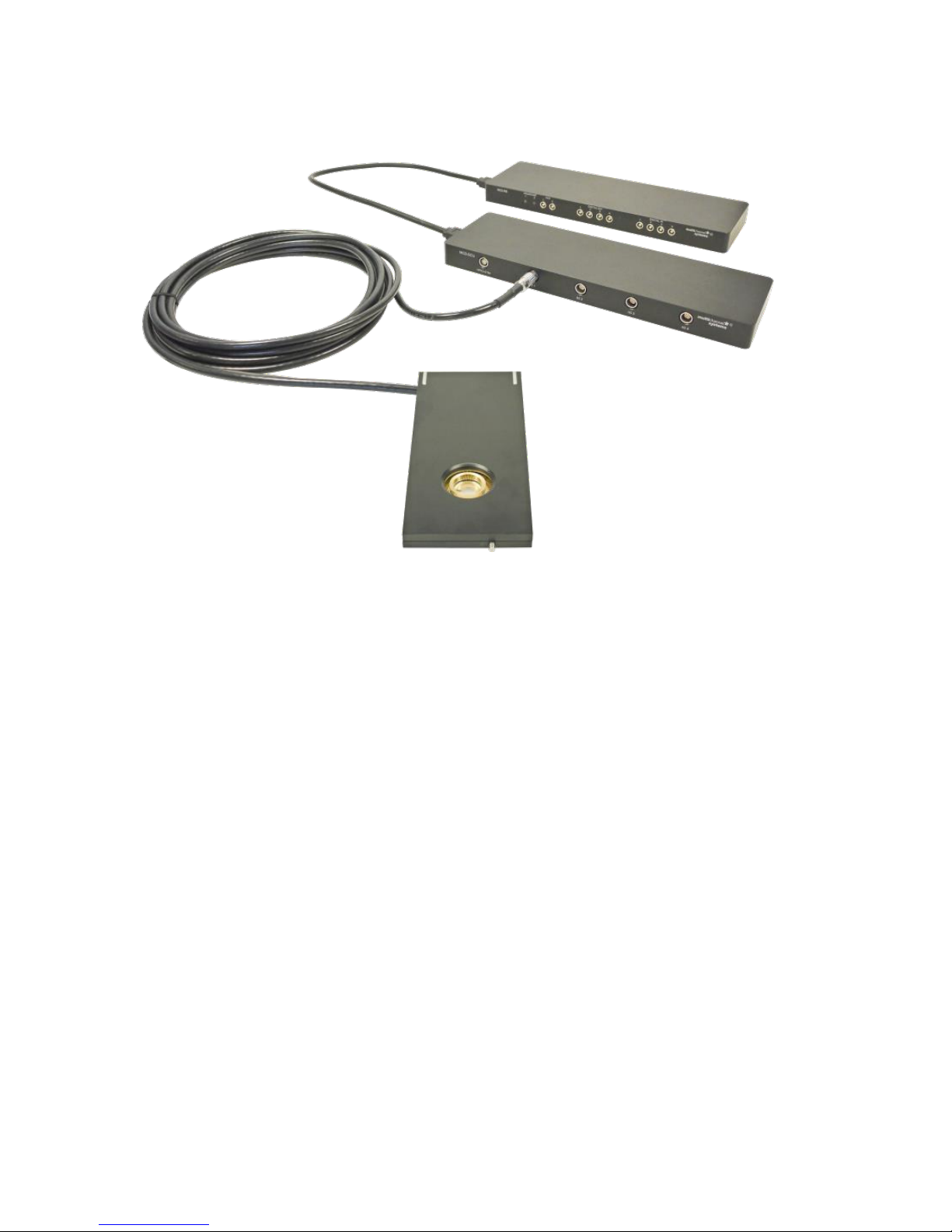
Hardware Components ............................................................................................... 8
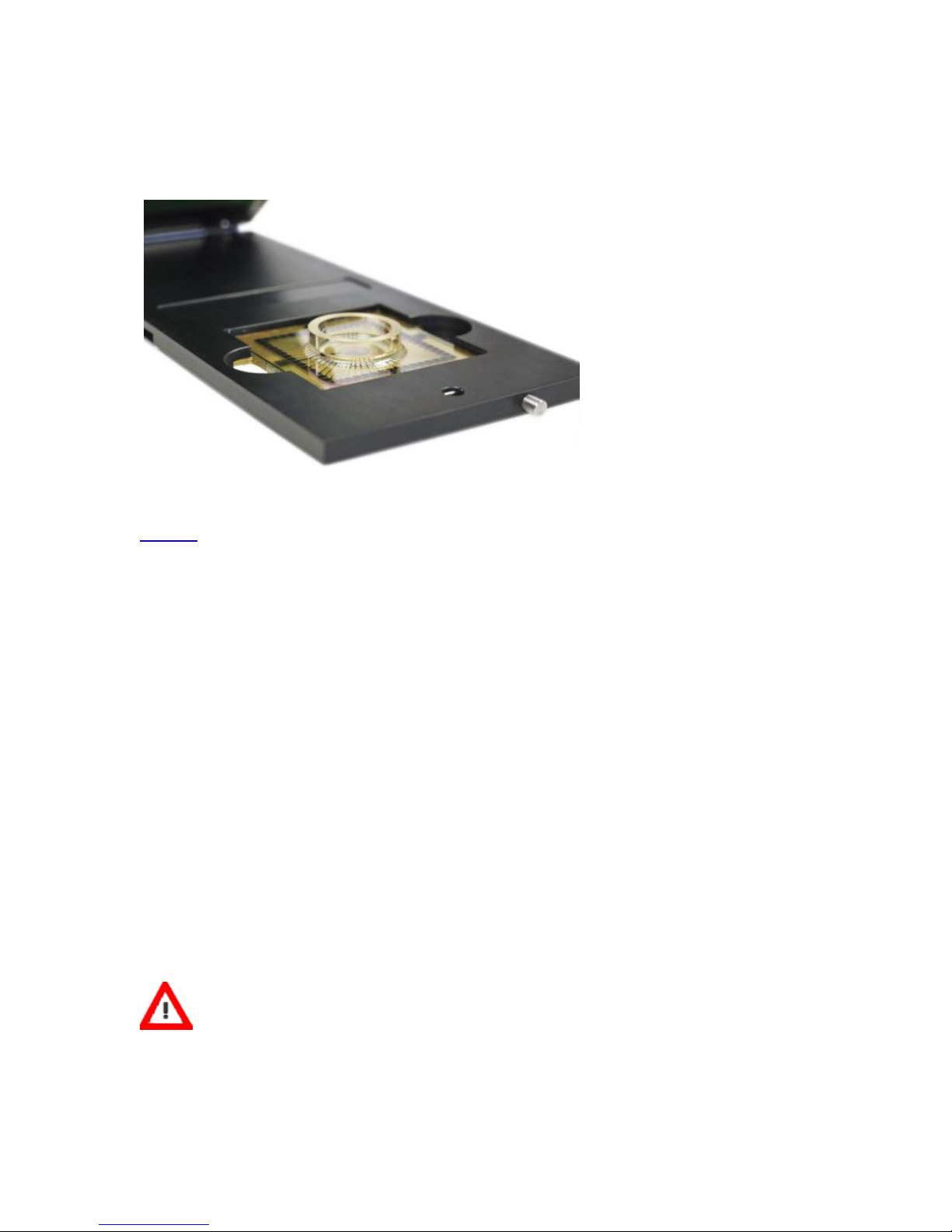
Headstage MEA2100-Mini .......................................................................................... 8
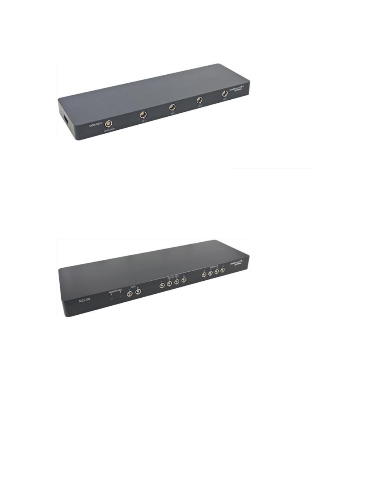
Signal Collector Unit MCS-SCU ................................................................................... 9
Interface Board MCS-IFB 3.0 Multiboot ....................................................................... 9
Front Panel ............................................................................................................ 10
Rear Panel.............................................................................................................. 10
Side Panel.............................................................................................................. 12
Software Multi Channel Suite................................................................................... 13
Software Installation.................................................................................................. 13
Multi Channel Experimenter ...................................................................................... 14
System Setup.............................................................................................................. 16
Connecting the Hardware Components .................................................................... 16
Setting up the MEA ............................................................................................... 17
First Functional Tests.................................................................................................. 17
MCS Filter Configuration........................................................................................... 20
Service and Maintenance .......................................................................................... 22
About Troubleshooting ............................................................................................. 23
No Computer Connection / No Recording Possible .................................................... 23
Triggering / Digital Input does not Work.................................................................... 24
Noise on Single Electrodes......................................................................................... 24
MEA is defective........................................................................................................ 25
Overall Noise / Unsteady Baseline .............................................................................. 25
Missing Spikes or Strange Signal Behavior ................................................................. 26
Technical Support....................................................................................................... 26

4
Appendix…………………………………………………………………………………….26
Technical Specifications ............................................................................................. 27
Pin Layout ................................................................................................................... 31
MCS-IFB 3.0 Multiboot Interface Board ..................................................................... 31
MEA2100-Mini Interface Board: Digital IN / OUT Connector .................................. 31
MCS-IFB 3.0 Multiboot Interface Board: 10-Pin Connector for Analog IN............... 32
ME2100 Interface Board: 20-Pin Connector (JTAG) for Digital Signal Processor...... 33
Contact Information .................................................................................................. 34

5
Welcome to the MEA2100-Mini-System
The MEA2100-Mini-System is a miniaturized in vitro recording system. The state of the art power
saving electronics allow to benefit from almost all advantages of the MEA2100 platform and still
be able to operate the system continuously in the incubator. Headstages have 60 recording channels
and two integrated stimulators each. Amplifier, stimulators, and A/D converters are all directly on the
headstage, which allows low-noise, high quality data acquisition.
The system consists of a signal collector unit (MCS-SCU) for up to four headstages. The MCS-CSU
also contains a connector for up to four outputs for optical LED stimulation. The signal collector is
connected via an eSATA cable to the interface board (MCS-IFB). It is possible to connect up to two
signal collector units to one MCS-IFB 3.0 Multiboot interface board, so a MEA2100-Mini-2-System
with two MCS-CSUs can operate up to eight headstages simultaneously.
Data is recorded, analyzed, graphed, and reviewed with the powerful and easy-to-use Multi Channel
Suite program from Multi Channel Systems MCS GmbH. The control functions of the internal
stimulator are also integrated into the software. The data format can be converted in other standard
formats with integrated software tools.
The modular nature of the system allows easy upscaling.

6
Before You Start
Important Safety Advice
Warning: Make sure to read the following advice prior to installation or use of the device
and the software. If you do not fulfill all requirements stated below, this may lead to
malfunctions or breakage of connected hardware, or even fatal injuries.
Warning: Always obey the rules of local regulations and laws. Only qualified personnel
should be allowed to perform laboratory work. Work according to good laboratory
practice to obtain best results and to minimize risks.
The product has been built to the state of the art and in accordance with recognized safety
engineering rules. The device may only
be used for its intended purpose;
be used when in a perfect condition.
Improper use could lead to serious, even fatal injuries to the user or third parties
and damage to the device itself or other material damage.
Warning: The device and the software are not intended for medical uses and must
not be used on humans.
Malfunctions which could impair safety should be rectified immediately.
High Voltage
Electrical cords must be properly laid and installed. The length and quality of the cords must
be in accordance with local provisions.
Only qualified technicians may work on the electrical system. It is essential that the accident
prevention regulations and those of the employers' liability associations are observed.
Each time before starting up, make sure that the power supply agrees with the specifications
of the product.
Check the power cord for damage each time the site is changed. Damaged power cords
should be replaced immediately and may never be reused.
Check the leads for damage. Damaged leads should be replaced immediately and may
never be reused.
Do not try to insert anything sharp or metallic into the vents or the case.
Liquids may cause short circuits or other damage. Always keep the device and the power
cords dry. Do not handle it with wet hands.
Requirements for the Installation
Make sure that the device is not exposed to direct sunlight. Do not place anything on top of the
device, and do not place it on top of another heat producing device, so that the air can circulate
freely.

7
Guarantee and Liability
The General conditions of sale and delivery of Multi Channel Systems MCS GmbH always apply.
The operator will receive these no later than on conclusion of the contract.
Multi Channel Systems MCS GmbH makes no guarantee as to the accuracy of any and all tests and
data generated by the use of the device or the software. It is up to the user to use good laboratory
practice to establish the validity of his / her findings.
Guarantee and liability claims in the event of injury or material damage are excluded when they are
the result of one of the following.
Improper use of the device.
Improper installation, commissioning, operation or maintenance of the device.
Operating the device when the safety and protective devices are defective and / or inoperable.
Non-observance of the instructions in the manual with regard to transport, storage,
installation, commissioning, operation or maintenance of the device.
Unauthorized structural alterations to the device.
Unauthorized modifications to the system settings.
Inadequate monitoring of device components subject to wear.
Improperly executed and unauthorized repairs.
Unauthorized opening of the device or its components.
Catastrophic events due to the effect of foreign bodies or acts of God.

8
Hardware Components
Headstage MEA2100-Mini
The first element of the MEA2100-Mini-System is the headstage with small footprint and operable
in a humid incubator. The MEA2100-Mini headstage is available with 60 channels and can be
ordered with a cable length of 5 m.
The data acquisition integrated in the headstage supports 60 electrode channels. Sampling rate,
signal range and bandwidth are adjusted via software control and are suitable for a broad range
of applications, from single unit spike recordings to field potentials from whole heart preparations.
Amplifier, stimulators and A/D converters are all directly on the headstage, which allows low-noise,
high-quality data acquisition. Two stimulus generator units are also integrated in each headstage,
which are able to independently deliver monophasic or biphasic rectangular pulses, ramps, sine
waves or random waveforms as single pulses or pulse trains. You can choose between current and
voltage driven stimulation and you can select each electrode for stimulation within the software.
An integrated blanking circuit (BC) disconnects the electrodes from the amplifiers during the
stimulation and reduces stimulus artifacts.
The cable of the MEA2100-Mini headstage connects to the signal collector unit MCS-SCU,
please read next chapter "Signal Collector Unit MCS-SCU".
Up to four MEA2100-Mini headstages can be operated with one MCS-SCU and up to two signal
collector units can be connected to one interface board MCS-IFB 3.0 Multiboot. Hence, in total
a system can record from up to 480 electrodes (8 individual 60-channel headstages). Electrode
raw data acquired from the probe is amplified and digitized by the analog / digital converter that
is integrated in the headstage at sampling rates of up to 50 kHz per channel. Data is transferred
via signal collector unit to the interface board with an eSATAp cable.
Warning: It is recommended to switch off the MEA2100-Mini-System on the interface
board whenever connecting or disconnecting headstages.

9
Signal Collector Unit MCS-SCU
The second element of the MEA2100-Mini-System is the signal collector unit MCS-SCU for up to
four headstages. The MCS-SCU also contains a connector to control up to four independent optical
stimulation devices. The control functions are integrated into the Multi Channel Experimenter
software. The 68-pin analog out (AO) connector on the rear panel of the MCS-SCU can be used
for a connection to third party devices via a 68-pin MCS high grade cable.
The signal collector unit and the interface board are connected with an eSATAp cable. Up to two
MCS-SCUs can be connected to one MCS-IFB 3.0 Multiboot.
Interface Board MCS-IFB 3.0 Multiboot
The interface board, the third element of the MEA2100-Mini-System, collects the data from one
or two attached MCS-SCUs and transfers them to the computer via USB 3.0.
Each MCS-IFB 3.0 Multiboot can load up to three different sets of firmware. With the appropriate
firmware, the same interface board can operate MEA2100 (-Mini), CMOS or Multiwell headstages
as well as ME2100-SCUs or W2100 receivers. Upgrades of an existing system with a different type
of headstage are available on request.
The Digital IN / OUT connector (68-pin MCS standard connector) for 16 digital in- and output bits
guarantees the communication with other devices. You can use the digital TTL inputs, for example,
for synchronizing the recording in MEA2100-Mini-System with other systems. The digital TTL outputs
can be used for triggering other devices, for example, an imaging setup.
Connect an audio system to the Audio Out (3.5 mm phone jack) to make electrical activity audible.
This audio output is in real-time. Headphones or a speaker can be directly plugged into the Audio
Out. Two channels at a time can be converted into sound.

10
Front Panel
From left to the right:
Two Status LEDs
The status LEDs indicate the link status of MCS-SCU 1 and / or MCS-SCU 2. They light up when
one or both signal collector units are connected to the MCS-IFB 3.0 Multiboot interface board via
eSATAp cable.
Auxiliary Channels
Two reserved auxiliary channels are available for future use. They have no function at the moment.
Digital IN / OUT
A Digital IN / OUT for 16 digital in- and output bits is available (68-pin MCS standard connector)
on the rear panel of the interface board. On the front panel four Digital IN and four Digital OUT
bits are also accessible via Lemo connector (DIG IN bit 0 to bit 3 and DIG OUT bit 0 to bit 3).
The Digital OUT delivers TTL pulses with 3.3 V. If access to more bits of the DIG IN / OUT channel
is required, it is necessary to connect a Digital IN / OUT extension Di/o board with a 68-pin standard
cable. This Di/o board is available as an optional accessory.
Power LED
The power LED near to the MCS logo on the front panel of the interface board should light up
when the MEA2100-Mini-System is "ON" and the device is connected to the power line. If not,
please check the power source and cabling.
Rear Panel
From left to right:
Toggle Switch On / Off
Toggle switch for turning the device on and off. The MEA2100-Mini-System is switched to status
"ON" when the toggle switch is switched to the left. The device is switched "OFF" when the toggle
switch is switched to the right. If the MEA2100-Mini-System is "ON", and the device is connected
to the power line, the Power LED on the front panel of the interface board should light up. If not,
please check the power source and cabling.

11
Power IN
Connect the power supply unit here. This power supply powers both, the headstage and
the interface board of the MEA2100-Mini-System. The device needs 12 V and 2.5 A / 30 W.
Ground
If an additional ground connection is needed, you can connect this plug with an external ground
using a standard common jack (4 mm).
Digital IN / OUT
A Digital IN / OUT for 16 digital in- and output bits is available via 68-pin MCS standard connector.
Please read chapter "MEA2100-Mini Interface Board: Digital IN / OUT Connector" on page 31 in
the Appendix for more information about the pin layout of the connector. The Digital IN / OUT
connection accepts or generates standard TTL signals. The Digital OUT delivers TTL pulses with 3.3 V.
TTL stands for Transistor-Transistor Logic. A TTL pulse is defined as a digital signal for communication
between two devices. A voltage between 0 V and 0.8 V is considered as a logical state of 0 (LOW),
and a voltage between 2 V and 5 V means 1 (HIGH).
The Digital OUT allows generating a digital signal with up to 16 bits and read it out, for example,
by using a Digital IN / OUT extension Di/o board. You can utilize this digital signal to control and
synchronize other devices with the MEA2100-Mini-System.
Bit 0 to 3 of the Digital OUT are separated and available as Lemo connector DIG OUT 0 to 3 on the
front panel of the interface board. So the DI/O extension is only necessary if more than four trigger
inputs or outputs are needed.
The Digital IN can be used to record additional information from external devices as a 16 bit encoded
number. The Digital IN is most often used to trigger recordings with a TTL signal. The 16 bit digital
input channels is a stream of 16 bit values. The state of each bit (0 to 15) can be controlled
separately. Standard TTL signals are accepted as input signals on the digital inputs.
Warning: A voltage that is higher than +5 Volts or lower than 0 Volts, that is, a negative
voltage, applied to the digital input would destroy the electronics. Make sure that you apply
only TTL pulses (0 to 5 V) to the digital inputs.
Analog Channels
Up to eight Analog IN channels are available via 10-pin connector. Please read chapter "MCS-IFB 3.0
Multiboot Interface Board: 10-Pin Connector for Analog IN" on page 32 in the Appendix for more
information about the pin layout.
The additional analog inputs are intended for recording additional information from external devices,
for example, for recording patch clamp in parallel to the MEA recording. Two of these channels
(No 1 and 2) are available via Lemo connectors on the rear panel of the interface board. You could
also use the analog inputs for triggering, but please note that the digital inputs DIG IN 0 to 3 are
intended for accepting TTL pulses. Signals on the analog channels are digitized and amplified with
a gain factor of 2.

12
Analog Channels 1 and 2
Two of the analog channels described above (analog channel 1 and 2) are directly accessible
via two Lemo connectors.
JTAG Connector
The JTAG connector has access to the digital signal processor DSP, but the DSP is not yet in use
in MEA2100-Mini-Systems.
USB 3.0 Connectors A and B
Both USB 3.0 connectors are used to transfer the amplified and digitized data from all data channels
and the additional digital and analog channels to any connected data acquisition computer via
USB 3.0 super speed (type A - micro B) cable. Connector A corresponds to eSATA input 1 on the
side panel, and connector B to the eSATA input 2. If both eSATA inputs are used, also both USB
connections must be used. Both USB cables must be connected to different USB 3.0 ports of the
computer, do not use an USB hub! Only use high grade USB 3.0 cables, as provided with the system.
Audio OUT
To the Audio Out (3.5 mm phone jack) you can connect an audio system to make one or two of the
electrode channels audible. This audio output is real-time. Headphones or speakers can be connected
directly to the AUDIO OUT. Select the audible channels via software. Only two channels at a time can
be converted into sound (Stereo).
Side Panel
On the side panel, there are two eSATA sockets for connecting one or two signal collector units
MCS-SCU to the interface board MCS-IFB 3.0 Multiboot. When using only one MCS-CSU, please
connect it to eSATA socket No 1 and use the USB A on the rear panel of the interface board for
the connection to the computer. Two MCS-CSUs with two USB 3.0 connections must be connected
to different USB 3.0 ports of the computer, do not use an USB hub! Only use high grade USB 3.0
cables, as provided with the system.

13
Software Multi Channel Suite
The Multi Channel Suite software, which is needed to operate the MEA2100-Mini-System,
is provided on a CD with the system. However, the latest version is always available for free
download from the MCS web site. Please check for updates on a regular basis to get all
the latest features and bugfixes. The Multi Channel Suite consists of three individual programs:
1. The Multi Channel Experimenter is the online data acquisition software.
2. The Multi Channel Analyzer is for offline analysis of data generated with
the Multi Channel Experimenter.
3. The Multi Channel DataManager allows to export Multi Channel Experimenter
data to 3rd party file formats.
Software Installation
For installation, download the respective *.exe files and follow the instructions on the screen.
System Requirements
For the Multi Channel Suite software, Microsoft Windows ® 10 or 8.1 operating systems are
required. English and German versions supported. Other language versions may lead to software
errors.
A computer with low performance may lead to performance limits more often; therefore, MCS
recommends an up-to-date computer optionally with a separate hard disk.
Please note that there are sometimes hardware incompatibilities of the MEA2100-Mini-System and
computer components; or that an inappropriate computer power supply may lead to artifact signals.
Please contact your local retailer for more information on recommended computer hardware.
Important: You need to have installed the latest MEA2100-Mini-System driver to operate the
MEA2100-Mini-System, which is automatically installed with the data acquisition software.
The installation may be invalid if the MEA2100-Mini-System does not respond. Please contact
Multi Channel Systems or your local retailer in this case.

14
Recommended BIOS Settings
The following automatic services of the Windows operating system interfere with the data storage
on the hard disk and can lead to severe performance limits in the data acquisition software. These
routines were designed for use on office computers, but are not very useful for a data acquisition
computer.
•Turn off Screen Saver.
•Turn off manual management of automatic Windows Update.
•Power Options: Power scheme: High performance. Never turn on system standby. It is also
not recommended to run any applications in the background when using the data acquisition
software.
•Be careful when using a Virus Scanner.
These programs are known to disturb the software and even data loss may occur. When using a
MEA2100-Mini-System, it is recommended to connect a high performance computer with a separate
hard disk for program files and data storage. The provided possibility to use up to 480 channels with
up to 50 kHz needs high memory capacity, therefore a SSD hard drive is recommended. Please
remove data and defragment the hard disk regularly to ensure optimal performance.
Multi Channel Experimenter
Open the Multi Channel Experimenter software. The Multi Channel Experimenter is the online data
acquisition software of the Multi Channel Suite package. Please read also the Multi Channel
Experimenter manual.
The software supports the MEA2100-Mini-System in all available headstage variations. One MCS-
SCU (Signal Collector Unit) with all attached headstages is always operated independently by one
instance of the software. The icon indicates which MCS-SCU it represents. 1 and 2 indicate the signal
collector unit connected to port 1 or 2 of the interface board. Once the MEA2100-Mini-System is
added to the instrument configuration, the MEA2100-Mini stimulator and the MCS-SCU stimulator
will also become available as instruments.
The MEA2100-Mini-System has three output ports: Electrode Raw Data (blue), Analog Data (green)
and Digital Data (red). MEA2100-Mini data sources have no input ports. The MEA2100-Mini-System
can be connected directly with any number of other instruments with blue or red input ports. The
green port can only be connected to the Recorder at the moment. There are no export options.

15
Drag the MEA2100-Mini data source icon into the main window and double click it to open the
control window.
The MEA2100-Mini data source control window shows all available data channels for all connected
headstages, and optionally also the additional analog input channels from the interface board.
One headstage is visible at a time. All headstages are shown with their serial number. Click on the
headstage to see the respective data. This has no influence on recording, all active channels from
all active headstages will be recorded, independently from the display.
The MEA layout, the settings for the MEA2100-Mini stimulator and other instruments connected to
the data source depend on the currently selected headstage. All settings apply only to the selected
headstage, which makes individual changes per headstage possible, and allows the independent
control of the stimulators in each headstage. For example, a filter connected to the MEA2100-Mini
data source can have different filter settings for each headstage. To adjust them, select the
respective headstage and the individual settings will be shown in the filter tool. The same applies
to the MEA2100-Mini stimulator. The stimulation paradigm can be different for each headstage,
changes only apply to the stimulator of the currently selected headstage.
Start the Test
Insert the provided Test Model Probe and click the Start DAQ button in the main menu.
The control window shows the raw data for all channels of the currently selected data source.
Click on any channel to see it magnified in the zoom display below. You should see a noise level
of approximately 20 µV peak to peak on all channels. In case of 50 Hz noise, shield the Test Model
Probe with a piece of aluminum foil connected to the ground connector on the interface board.
Repeat the procedure with all attached headstages.

16
System Setup
Connecting the Hardware Components
The setup of the MEA2100-Mini-System is very simple. Familiarize yourself with the components
as described in the chapters above, then go through the step-by-step setup instruction below.
Provide a power supply in the immediate vicinity of the installation site.
Place all devices on a stable and dry surface, where the air can circulate freely and the devices
are not exposed to direct sunlight.
Set up the computer with installed data acquisition program.
Install the software from the installation volume if it is not already installed. The MEA2100-
Mini-System is a plug and play device. The driver is automatically installed together with the
data acquisition program.
Connect the headstage/s via the provided cable/s to the signal collector unit MCS-SCU.
Do not mistake the headstage inputs (HS1 to HS4) with the Opto Stim input.
If the headstages are operated in the incubator, route the cables through the access port
available in the back of most incubators. Do not route the cables through the rubber seal
of the front door. The SCU und the IFB must remain outside the incubator.
Connect the signal collector unit MCS-SCU via the eSATAp cable to the interface board.
Connect one or both USB 3.0 micro ports of the interface board to a free USB 3.0 port of the
data proceeding acquisition computer. Connector A corresponds to eSATA input 1 on the
side panel, and connector B to the eSATA input 2. If both eSATA inputs are used, also both
USB connections must be used. Do not use an USB hub and also avoid USB ports on the front
panel of the computer, as they are often connected to the mainboard via an internal hub.
Connect the interface board via the power supply unit to a power outlet of the same electrical
system (connected to the same ground / earth wire) as all other components of the setup, for
example, the computer or shielding.
If necessary, connect the system to an external ground.

17
Turn the toggle switch at the rear panel of the interface board on.
Check the power LED. It should light up as soon as the power line is connected,
and the toggle switch is switched on. If not, check the power source and cabling.
Warning: It is recommended to switch off the MEA2100-Mini-System on the interface board
whenever connecting or disconnecting headstages.
Setting up the MEA
Open the lid of the headstage. Place the MEA chip inside the MEA2100-Mini headstage. The MEA
is not rotationally symmetrical, so take care for the orientation of the MEA. Please read the respective
datasheet for the MEA layout and orientation.
Important: MEAs are not symmetrical! That is, why the writing (for example NMI, LEITER, MEA type)
on the MEA chip should be on the right side viewed from the front, when the headstage is open.
MEAs with one big internal reference electrode should be placed with reference electrode to the left
side in the headstage. Otherwise, the MEA layout will not match with the pin layout of the channel
map in the data acquisition software.
Warning: Spilled liquid can damage or even completely destroy the electronics of the
MEA2100-Mini headstage. Please be careful when setting up your perfusion system and
when starting the perfusion. Take care that the flow rates of the inlet and outlet flow
match so that flooding of the amplifier is efficiently prevented.

18
First Functional Tests
Each MEA2100-Mini-System has been thoroughly tested at the factory site before delivery. However,
you may want to perform some tests yourself before you begin your experiment to exclude any
damage that might have occurred during transportation. Multi Channel Systems recommends
running these tests after the setup of your system before actually starting experiments on animals.
The detailed function of the software package Multi Channel Suite, Multi Channel Experimenter,
Multi Channel Analyzer, and Multi Channel DataManager is described in the respective manuals.
The manuals are available on the MCS web site or directly from a link, provided in the option
“Help” of the “Settings” section of each software. Please see the screenshot below.
Please read also chapter "Software" on page 13 in this manual.
Test Model Probe
Please use the provided test model probe to test the functionality of the MEA2100-Mini-System.
Connect the test model probe "Test-60MEA" to each headstage. The test model probe simulates
a MEA with a resistor of 220 kand a 1 nF capacitor between ground and electrode for each of
the 60 electrodes. It can be used for testing the noise level of the electrodes of the MEA2100-Mini-
System.
For the intention to check the noise level of the MEA2100-Mini-System without external signals,
please connect “Signal Source” and “Signal Ground” sockets for a short circuit. The second ground
pin must be connected to the headstages ground. For ground connection and for short circuit please
use the provided cable CB-GND. Please read also the datasheet "Test-60MEA".

19
Signal Generator 60MEA2100-SG
A MEA Signal Generator is a convenient tool adapted for MEA2100-Mini-Systems. Use the
60MEA2100-SG instead of setting up an experiment with biological sample for training, controlling,
and troubleshooting purposes. This reduces the number of animal experiments and saves laboratory
equipment. Please read also the "Signal Generator" manual and datasheet "60MEA2100-SG".
Temperature Controller TC01 or TC02
The MEA2100-Mini-System features a heating element with a PT100 temperature sensor. If you
connect a temperature controller TC02 for example, to the heating element via D-Sub 9 connector,
the heating element guarantees constant temperature conditions for the biological sample, placed
on the MEA. Please read the manual Temperature Controller TC01/02.
Perfusion Cannula PH01
When using a perfusion system, the perfusion cannula PH01 with heating element and sensor can be
connected to a temperature controller TC02. The perfusion cannula for controlled fluid temperature
is very useful for general perfusion purposes, whenever the fluid stream needs to be temperature
controlled. Magnetic holders for the PH01 and a suction cannula are available as optional accessory.
A steel plate fitting the headstage of the MEA2100-Mini for the magnetic holders is included in the
scope of delivery. Please read the manual PH01.

20
MCS Filter Configuration
The MCS Filter Configuration software is an add on program for changing the hardware filter
settings by the software. No firmware update is necessary. You can operate the MCS Filter
Config software with MEA2100-Systems, MEA2100-Mini-Systems and ME2100-Systems.
Please install the MCS Filter Configuration software by clicking the “McsFilterConfig.exe” file.
Follow the installation guide as usual.
Main window of the MCS Filter Configuration program, Version 1.1.0
The MCS Filter Configuration program for changing the hardware filter setting of the ME2100-
or MEA2100(-Mini)-System is self-explanatory via tool tips. It is possible to control each headstage
connected separately.
Define the “MEA Devices” from the drop-down box if more than one headstages or headstages with
two MEA slots are available. Press "Refresh" button to update the settings. The actual settings for
“High and Low Pass Filter” for the selected headstage are displayed. If the actual settings are not on
the drop-down list, “Custom” will be displayed.
Select the order of the filter from the first drop-down box. The message “The filter order determines
the steepness of the filter” is shown. The higher the order, the steeper the cut off.
Table of contents
Other Multi Channel Systems Recording Equipment manuals