N219
CONTENTS
1 INSTALLATION PRECAUTIONS............2
1-1 BEFORE INSTALLATION................2
1-2 PARTS IDENTIFICATION................3
1-3 KNOCKOUTS..................................3
2 DETECTION AREA.................................4
2-1 OUTLINE OF DETECTION AREA...4
2-2 HOW TO REDUCE THE LONG
RANGE DETECTION AREA............6
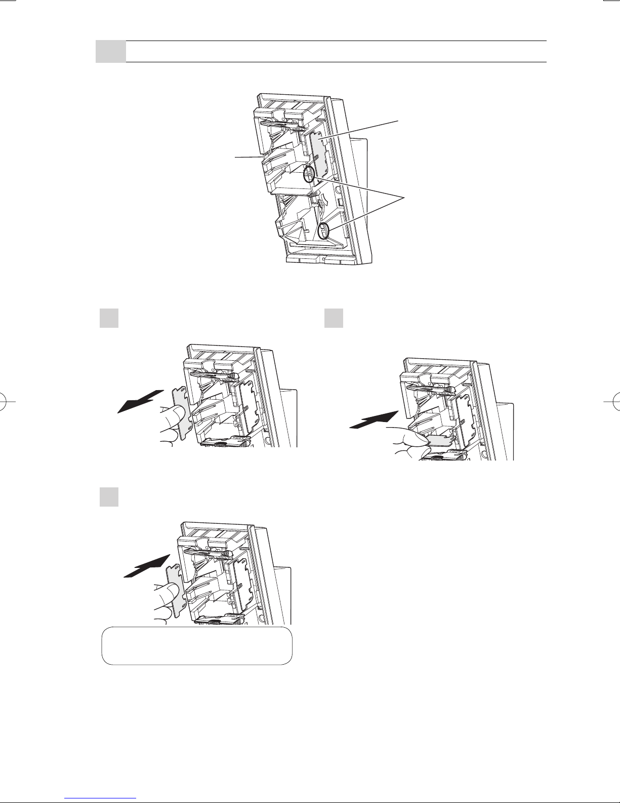
2-3 HOW TO DEACTIVATE THE SHORT
RANGE DETECTION AREA............8
3 PREPARATIONS ..................................10
3-1 TRANSMITTER PREPARATION...10
3-2 BATTERY PREPARATION ............ 11
4 INSTALLATION (BATTERY AND
TRANSMITTER)...................................12
4-1 INSTALLING THE BATTERY.........12
4-2 INSTALLING THE TRANSMITTER
AND BATTERY BOX .....................15
5 INSTALLATION (BRACKET AND
MAIN UNIT) ..........................................16
5-1 INSTALLING WITH BRACKET......16
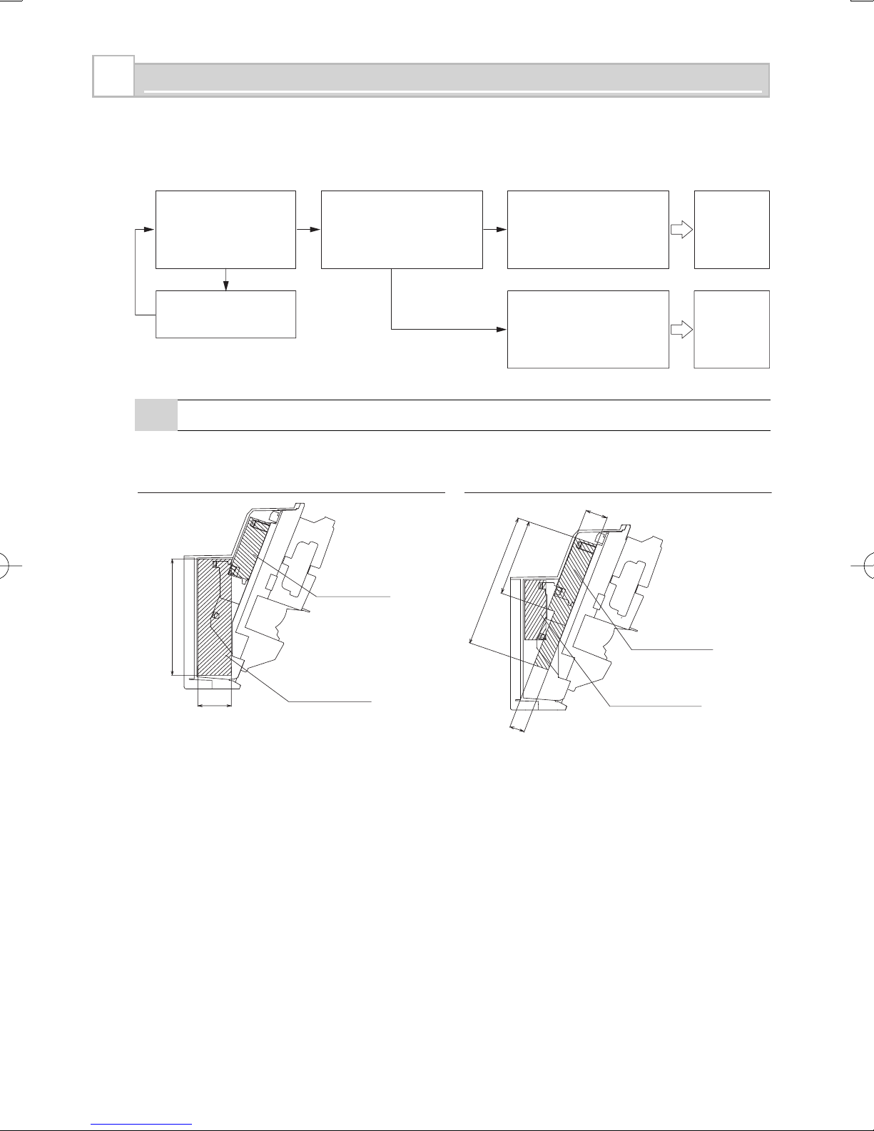
5-2 ADJUSTING THE VERTICAL
ANGLE...........................................18
5-3 INSTALLING WITHOUT
BRACKET......................................18
5-4 WIRING .........................................19
5-5 WALL TAMPER (OPTION) ............20
6 WALK TEST..........................................22
7 SETTING ..............................................22
8 LED INDICATION .................................26
9 SPECIFICATIONS ................................27
9-1 SPECIFICATIONS .........................27
9-2 DIMENSIONS................................28
HX-80NRAM Battery operated with 2 PIRs and
anti-masking
Battery operated
Battery saving logic
Compatible with most wireless transmitter
Long distance detection area (24.0 m)
Flexible detection area setting with plates and flaps
Unique pyro element
Intelligent AND logic
Dual signal processing logic
Vegetation sway analysis logic
Digital anti-masking
•
•
•
•
•
•
•
•
•
•
NO.59-1620-0
INSTALLATION INSTRUCTIONS
High Mount
Outdoor Detector
HX-80NRAM
High Mount
Outdoor Detector
HX-80NRAM
- 1 -
HX-80NRAMEN.indd1HX-80NRAMEN.indd1 2010/08/209:18:412010/08/209:18:41