MultiChannel MPA32I User manual

32-Channel Miniature Preamplifier
Manual

Information in this document is subject to change without notice.
No part of this document may be reproduced or transmitted without the express written
permission of Multi Channel Systems MCS GmbH.
While every precaution has been taken in the preparation of this document, the publisher
and the author assume no responsibility for errors or omissions, or for damages resulting
from the use of information contained in this document or from the use of programs and
source code that may accompany it. In no event shall the publisher and the author be liable
for any loss of profit or any other commercial damage caused or alleged to have been caused
directly or indirectly by this document.
© 2018 Multi Channel Systems MCS GmbH. All rights reserved.
Printed: 16. 04. 2018
Multi Channel Systems
MCS GmbH
Aspenhaustraße 21
72770 Reutlingen
Germany
Phone +49-71 21-909 25 -0
Fax +49-71 21-909 25 -11
sales@multichannelsystems.com
www.multichannelsystems.com
Microsoft and Windows are registered trademarks of Microsoft Corporation. Products that
are referred to in this document may be either trademarks and/or registered trademarks
of their respective holders and should be noted as such. The publisher and the author
make no claim to these trademark.

Table of Contents
Table of Contents 1
1Important Information and Instruction 1
1.1 Operator's Obligations 1
1.2 Guarantee and Liability 1
1.3 Important Safety Advice 2
2Welcome to the MPA32I 3
3Setting Up and Connecting the MPA 4
3.1 General Setup Recommendations 4
3.2 Testing the Noise Level of the Setup 5
4Setting up MC_Rack 6
5Connecting FlexMEAs 8
5.1 EcoFlexMEAs 10
5.1.1 Connecting 32-Channel NeuroNexus Probes 11
5.1.2 Adapter-NN-32 Pin Layout 12
5.2 Connecting 54-Channel NeuroNexus Probes 13
6Service and Maintenance 15
7Pin Layout 16
7.1 Power Supply 16
7.2 Test Model Probe 17
8Contact Information 18
9Technical Specifications MPA32I 19

Important Information and Instruction
1
1Important Information and Instruction
1.1 Operator's Obligations
The operator is obliged to allow only persons to work on the device, who
are familiar with the safety at work and accident prevention regulations and have been instructed
how to use the device;
are professionally qualified or have specialist knowledge and training and have received
instruction in the use of the device;
have read and understood the chapter on safety and the warning instructions in this manual
and confirmed this with their signature.
It must be monitored at regular intervals that the operating personnel are working safely.
Personnel still undergoing training may only work on the device under the supervision of
an experienced person.
1.2 Guarantee and Liability
The General conditions of sale and delivery of Multi Channel Systems MCS GmbH always apply.
The operator will receive these no later than on conclusion of the contract.
Multi Channel Systems MCS GmbH makes no Guarantee as to the accuracy of any and all tests
and data generated by the use of the device or the software. It is up to the user to use good
laboratory practice to establish the validity of his findings.
Guarantee and liability claims in the event of injury or material damage are excluded when they
are the result of one of the following.
Improper use of the device.
Improper installation, commissioning, operation or maintenance of the device.
Operating the device when the safety and protective devices are defective and/or inoperable.
Non-observance of the instructions in the manual with regard to transport, storage, installation,
commissioning, operation or maintenance of the device.
Unauthorized structural alterations to the device.
Unauthorized modifications to the system settings.
Inadequate monitoring of device components subject to wear.
Improperly executed and unauthorized repairs.
Unauthorized opening of the device or its components.
Catastrophic events due to the effect of foreign bodies or acts of God.

Important Information and Instruction
2
1.3 Important Safety Advice
Warning: Make sure to read the following advices prior to install or to use the device and the
software. If you do not fulfill all requirements stated below, this may lead to malfunctions or
breakage of connected hardware, or even fatal injuries.
Warning: Obey always the rules of local regulations and laws. Only qualified personnel should be
allowed to perform laboratory work. Work according to good laboratory practice to obtain best
results and to minimize risks.
The product has been built to the state of the art and in accordance with recognized safety
engineering rules. The device may only
be used for its intended purpose;
be used when in a perfect condition.
Improper use could lead to serious, even fatal injuries to the user or third parties and damage
to the device itself or other material damage.
Warning: The device and the software are not intended for medical uses and must not be used
on humans.
Malfunctions which could impair safety should be rectified immediately.
Any physical damage of the cable, such as a broken cable, causes a physical damage of the
miniature preamplifier that cannot be repaired.
Protect the device from heat. Do not autoclave!
You can clean the connectors with distilled water in an ultra sonic bath, but keep the cable away
from the fluid. Dry the device with compressed air.
Use and keep the device always in a dry environment. Do not expose it to fluids or vapor for
a longer period of time.

FlexMEAs
3
2Welcome to the MPA32I
The 32-Channel Miniature Preamplifier MPA32I is connected to the microelectrodes for providing
the initial tenfold amplification stage.
It has additional common ground and reference electrode inputs. The reference electrode
is ideally identical to the recording electrodes and placed into a comparable but inactive area or
tissue. Background or noise signals that are picked up by both the reference electrode and the
recording electrodes are removed.
The metal case provides electrical shielding. Electrode damage is prevented by the very
low bias current. The high input impedance ensures stable long-term recordings:
Ideally, the input impedance would be infinite. As low voltages are generally recorded, a high
current would flow if the input impedance were low. As a result, the amplifier would not be able
to deliver the current, and the voltage would break down. The miniature preamplifier has a high
input impedance to avoid this problem.
Adapters for all standard microelectrodes such as NeuroNexus probes (from
www.neuronexustech.com) for acute and chronic implantations ensure a close proximity to the
probe to minimize signal loss and cross talk. Adapters are not included in the standard scope of
delivery and have to be ordered separately. For custom adapters, please ask your local retailer or
contact Multi Channel Systems.

FlexMEAs
4
3Setting Up and Connecting the MPA
3.1 General Setup Recommendations
In the following, you find general recommendations for the installation.
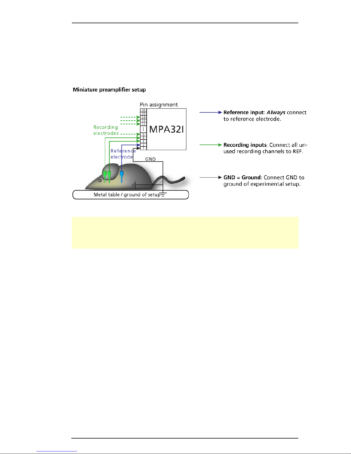
Important: It is important that the complete setup refers to a single common ground. The
reference input has always to be connected. It is recommended to use a reference electrode.
However, if you are not using a reference electrode, connect the reference input to ground
(GND). Otherwise, noise picked up by the reference input will be subtracted from the recording
signals. This will either lead to signal loss or to a very high noise level.
1. Ground the animal with a ground electrode of large surface area, for example, a liquid gel
adhesive electrode,that is connected to the ground of the setup, for example, a large metal
table or a Faraday cage, to avoid pickup of noise from the environment. The ground electrode
is best positioned in an electrically inactive region (not near muscle, nor heart), for example, at the
belly.
2. Connect the GND input or the metal case of the miniature preamplifier to the common
ground of the setup. (The GND input is internally connected to the metal case.)
3. Connect the reference electrode to the reference input of the miniature preamplifier.
Generally, a reference electrode is inserted into non-active tissue of the experimental model.
The reference electrode should be identical to the recording electrode so that both electrodes see
the same background noise. This is necessary because despite the grounding, the animal’s body
often has not exactly a potential of zero, due to the electrode impedance, for example. The
background noise is then subtracted from the recording signal, increasing the signal to noise ratio.
Please note that this may not work if the complete setup is not properly grounded.
4. (Optional) If two reference electrodes are used, connect the second electrode to the free
reference input. Otherwise, leave it free. It is generally not necessary to use a second reference
electrode. It can be used to enlarge the surface area of the reference, though.
5. Connect the recording electrodes to the recording channels of the miniature preamplifier.
You can either use single electrodes or multitrodes with the miniature preamplifier. MCS provides
adapters for standard probes.

FlexMEAs
5
6. Connect all unused recording channels to the GND input or to the reference electrode if the
reference and ground electrode of the amplifier are short circuited, to avoid noise pickup. As the
total amplifier gain generally lies in the range of 1000, even very small noise signals may generate
high noise signals.
7. If you are not using a Faraday cage, it might be necessary to shield the complete setup with
aluminum foil or similar to prevent electrical interference from the outside. Connect the aluminum
foil to the ground of the setup (for example, the metal table).
Troubleshooting: If you observe problems with noise, check that the ground of the setup
is connected to exactly the same ground as the data acquisition computer. For example,
connect the metal table to the ground / earth wire of a free power outlet (of the same electrical
system), as the computer is generally connected to ground/earth via the power plug, too.
Also, connect the data acquisition computer’s metal case with a thick ground wire
to the ground of the setup (for example, the metal table), preferably with a 4 mm plug.
3.2 Testing the Noise Level of the Setup
A terminal plug that connects all inputs to ground, and a test model probe that mimics
the electrode impedance are available for testing the noise level of the setup.
Note: Please note that the test model probe has to be ordered separately.
All instruments were thoroughly tested at the factory site before delivery. The suggested tests
are mainly intended for optimizing and troubleshooting your setup, to exclude any damage
that might have occurred during transportation, or to fulfill your own guidelines, for instance.
It will take only a few minutes time and can save time and trouble in the long run. Multi Channel
Systems recommends running these tests before you start your real experiments.
1. Connect the terminal plug to one miniature preamplifier and the test model probe to the other
as shown in the picture (do not mismatch the polarity). If you have only one MPA32I, you can
perform the two tests consecutively.
2. Connect the MPA32I with the test model probe to channels 1 to 32 of the signal collector.
3. Connect the MPA32I with terminal plug to channels 33 to 64 of the signal collector.
4. Make sure that all other connections are appropriate, and that your setup has an appropriate
grounding and shielding as recommended in the chapter “General Setup Recommendations”.

FlexMEAs
6
4Setting up MC_Rack
Please refer to the MC_Rack Manual for more information.
Start MC_Rack.
Open the file MPA32I_NoiseTest.rck on the installation volume (see folder Tutorial).This rack
contains the virtual MC_Card instrument as data acquisition device with a continuous raw data
display and an Analyzer to measure the peak-to-peak amplitude.
Click Start to start the recording.
—OR —Set up the rack on your own:
Click Data Source Setup on the Edit menu. Select a 1-dimensional layout. Select the number
of electrode channels (at least 32).
Add the data acquisition to your virtual rack.
In the tree view pane of the virtual rack, select the data acquisition, and click the Hardware
tab. Enter the total amplifier gain according to the specifications of the instruments. For example,
for a miniature preamplifier with a gain of 10 and a following filter amplifier with a gain of 100,
the total gain is 1000.
Select an input voltage range of –819.2 to +818,8 mV and a sampling rate of 10000 Hz.
On the Edit menu, click Add Data Display to add a raw data display to your virtual rack.
In the virtual rack tree view pane, select the Display 1 and click the Layout tabbed page.
Set up a channel map with channels 1 to 64.
Adjust the display ranges to 500 ms and +/–50 µV.
On the Edit menu, click Add Analyzer to add an Analyzer to the virtual rack. Select all or two
typical channels on the Channels tabbed page. Select the Peak-Peak Amplitude parameter on
the Analyzer tabbed page.
On the Edit menu, click Add Parameter Display to add a Parameter Display to the virtual rack.
In the virtual rack tree view, select the Display 2 and click the Layout tabbed page. Set up
a channel map with all channels that were assigned to the Analyzer.
Click the Ranges tabbed page and enter 0 to 10 s for the x- range and 0 to100 µV for the
y- range.

FlexMEAs
7
Typical Results
Typical results of this test are shown in the following screen shot. The filter amplifier used for this
test had a gain of 100 and a bandwidth of 0.5 to 5000 Hz (FA64I-100-0.5-5000). If you use a
filter amplifier with a narrower bandwidth, you can generally expect a slightly lower noise level.
Noise level test with #MPA8I and FA64I-100-0.5-5000 filter amplifier.
The noise level is 60 µV peak to peak with the provided test model probe (channels 1 –32)
and 20 µV peak to peak with grounded inputs (channels 33 –64). The top window shows
raw data; the bottom window shows the extracted peak-to-peak amplitudes of channels
1 and 33. (The miniature preamplifier was shielded by a metal case connected to the ground /
earth of the test lab.)

FlexMEAs
8
5Connecting FlexMEAs
FlexMEA36, plastic spacer and adapter (ADPT-FM-32) connected to a 32-channel miniature
amplifier MPA32I.
The side with no screws is considered the top side of the MPA32I. If the adapter is oriented
as shown in the figure, the FlexMEA36 is inserted with the contact pads facing downward.
For connecting the FlexMEA72 you need the adapter ADPT-FM-72. Please see the datasheet
FlexMEA72 in the Appendix.
Connecting the FlexMEA36
The FlexMEA adapter has a drawer for inserting the FlexMEA36. Open the slot of the white
drawer. Grip the sides of the white slot cover with your fingers and carefully pull open the slot
cover only a little bit (about 1 or 2 mm). Do not demount the cover as the plastic supports might
break easily.
Insert the FlexMEA36 into the slot of the drawer, with the contact pads upside down .Insert
the plastic spacer into the slot of the drawer.
Important: Please use a thin plastic spacer between the FlexMEA36 and the connector so that
the contact pads make a tight contact to the connector pins. Otherwise, the FlexMEA36 will
sit too loose and will have a bad contact resulting in a higher noise level. The spacer should be
placed on the opposite side of the contact pads of the FlexMEA36 in the drawer.
Carefully push back the slot cover of the white drawer until it locks.

FlexMEAs
9
FlexMEAs
FlexMEAs are made of flexible polyimide material (Polyimide 2611 foil), perfect for in vivo
and special in vitro applications. Only 12 µm "thick" and weighing less than 1 g,
the FlexMEA biosensor is very thin and lightweight.
FlexMEA36 has 32 titanium nitride (TiN) electrodes plus two
internal reference electrodes and two ground electrodes.
The flexible base is perforated for a better contact with the
surrounding tissue.
The electrodes have a diameter of about 30 µm with an
interelectrode distance of 300 µm.
Contact pads and conducting material is pure gold.
FlexMEA72 has 72 titanium nitride (TiN) electrodes plus
four internal reference electrodes and four ground
electrodes. The flexible base is perforated for a better
contact with the surrounding tissue.
The electrodes have a diameter of about 100 µm with
an interelectrode distance from 625 to 750 µm.
Contact pads and conducting material is pure gold.
Using FlexMEAs
FlexMEAs are usually connected to a headstage preamplifier that is connected to a filter amplifier
or programmable gain amplifier (see also the ME-System product line of Multi Channel Systems
MCS GmbH). FlexMEAs can be via adapter connected to a 32-channel miniature preamplifier
MPA32I from Multi Channel Systems for in vivo experiments. FlexMEAs are stable at a
temperature range from 10 °C to 40 °C.
Warning: Do not autoclave or sterilize FlexMEAs by heat. These MEA types are not heat stable
and will irreversibly damaged if the temperature is too high.
Do not use ultrasonic bath for cleaning!

FlexMEAs
10
5.1 EcoFlexMEAs
EcoFlexMEAs are made of flexible polyimide material (Kapton), perfect for in vivo and special in
vitro applications. Only 50 µm "thick" and weighing less than 10 g, the EcoFlexMEA biosensor
is thin and lightweight.
EcoFlexMEA36 has 32 gold electrodes plus two internal reference electrodes and two ground
electrodes. The flexible base is perforated for a better contact with the surrounding tissue. The
gold electrodes have a diameter of about 50 µm with an interelectrode distance of 300 µm and
an impedance of approximately 50 kOhm. Contact pads and conducting material is pure gold.
EcoFlexMEA24 has 24 gold electrodes plus two internal reference electrodes and two ground
electrodes. The flexible base is perforated for a better contact with the surrounding tissue. The
gold electrodes have a diameter of about 80 µm with an interelectrode distance of 300 µm and
an impedance of approximately 50 kOhm. Contact pads and conducting material is pure gold.
Using EcoFlexMEAs
EcoFlexMEAs are usually connected to a headstage preamplifier MPA31I that is connected to
a filter amplifier or programmable gain amplifier (see also the ME-System product line of Multi
Channel Systems MCS GmbH). EcoFlexMEAs can be directly connected to a 32-channel miniature
preamplifier from Multi Channel Systems for in vivo experiments. EcoFlexMEAs are stable at a
temperature range from 10 °C to 125 °C and can be autoclaved.

FlexMEAs
11
5.1.1 Connecting 32-Channel NeuroNexus Probes
Important: REF has to be connected for obtaining a proper signal.
Insert the pin array of the NeuroNexus probe into the black connector of the ADPT-NN-32.
Connect the MPA32I to the adapter outputs. Make sure that the orientation of the MPA32I
is correct (see illustration).

FlexMEAs
12
5.1.2 Adapter-NN-32 Pin Layout
The indicated numbers are the ME-System channel numbers that will show up in the data
acquisition program. GND is the ground, REF is the reference input of the miniature preamplifier
and “nc”means not connected.
Channel Assignment NeuroNexus Probe to MPA32I and Data Acquisition Program
The following list shows the assignment to the electrode numbers as given by NeuroNexus
Technologies
Pin Layout ADPT-NN-32
MPA32I Software ADPT-NN-32
Pin No Channel Electrode
1 GND
2 REF REF
3 CH 1 EL 17
4 CH 2 EL 21
5 CH 3 EL 18
6 CH 4 EL 23
7 CH 5 EL 19
8 CH 6 EL 25
9 CH 7 EL 20
10 CH 8 EL 27
11 CH 9 EL 29
12 CH 10 EL 31
13 CH 11 EL 32
14 CH 12 EL 30
15 CH 13 EL 28
16 CH 14 EL 26
17 CH 15 EL 24
18 CH 16 EL 22
19 CH 17 EL 1
20 CH 18 EL 3
21 CH 19 EL 2
22 CH 20 EL 5
23 CH 21 EL 4
24 CH 22 EL 7
25 CH 23 EL 6
26 CH 24 EL 9
27 CH 25 EL 8
28 CH 26 EL 13
29 CH 27 EL 11

FlexMEAs
13
30 CH 28 EL 14
31 CH 29 EL 10
32 CH 30 EL 15
33 CH 31 EL 12
34 CH 32 EL 16
35 REF
36 GND
5.2 Connecting 54-Channel NeuroNexus Probes
Important: REF has to be connected for obtaining a proper signal.
Connect the two MPA32I to the ADPT-NN-54 adapter outputs. Make sure that the orientation
of the amplifiers is correct (see illustration).

FlexMEAs
14
ADPT-NN-54 Pin Layout
Numbers in italics are the MPA32I pin numbers. The electrode numbers are aligned
to the input pins of the MPA32I.
The next figure shows the numbering of the polytrode electrodes.

Service and Maintenance
15
6Service and Maintenance
Cleaning the Connectors
Warning: It is recommended to avoid the use of cleaning solutions to avoid corrosion. If a wet
cleaning is required, use distilled water. Make sure that only the connectors touch the liquid;
do not submerge the miniature preamplifier or the cable. Otherwise, you can fatally damage
the electronics.
Clean the connectors with 70 % alcohol and cotton swabs from time to time.
If this does not provide satisfying results, insert only the connectors into a small beaker with
acetone or alcohol and treat them in an ultrasonic bath for 10 to 20 s. Air-dry the miniature
preamplifier for about 5 min before use.
You can also clean the connectors with distilled water in an ultra sonic bath. Dry the connectors
with compressed air immediately after sonication and let the amplifier air dry for at least 6 h
before use.
Sterilization
Warning: Do not autoclave or sterilize miniature preamplifiers by high heat (above 70 °C) or vapor.
The resin is not heat-stable and may deform under heat. Vapor can lead to a corrosion of the
electronics.
Miniature preamplifiers can be sterilized with standard methods that are not based on high heat
or vapor, for example, with 70 % ethanol, UV-light, or by thermal sterilization in an oven at
56 °C with an incubation time of 8 hours.

Pin Layout
16
7Pin Layout
7.1 Power Supply
Supply voltage is applied to the output connector pins 19 and 37. The voltage source should
supply a stable noise-free voltage. Do not exceed the maximum voltage.
Pin 19: –3 V to –8 V
Pin 37: +3 V to +8 V
Warning: Do not mismatch the polarity of the power supply. A false connection may damage
the unit.
Input Connector
This illustration shows the pin layout viewed from the front, with the case screws upside down.
The two reference inputs are used for connecting a reference electrode. Both inputs are equal,
so it does not matter which of the two inputs is used. If both are used, the mean of both
reference signals is used as reference.
Output Connector
The signal ground is connected to the ground of the amplifier. The signal ground is used as the
reference for the following filter amplifier.

Pin Layout
17
7.2 Test Model Probe
Test signal IN: You can use the jumper to connect the signal input pin (Signal IN) to ground
(standard situation for a noise level test), or you can connect a data source, for example, a sine
wave generator to the input (and the ground of the test signal to the signal ground input) to test
the signal distribution. The input signal is distributed across all recording channels.
REF I N: The standard situation in an experiment should be that the reference electrode has
properties identical or close to the recording electrodes. You can remove the jumper to connect
the reference output of the test model probe to the same resistors as the recording channels to
mimic the experimental situation, or you can use the jumper to connect the reference output to
ground.
DC
resistance
4.7 M
Dynamic
resistance
330 k
Capacitance
150 pF
Table of contents
Other MultiChannel Amplifier manuals
Popular Amplifier manuals by other brands

JL Audio
JL Audio MV600/6i Connection guide

TV One Multimedia Solutions
TV One Multimedia Solutions 1T-VGA-412 instruction manual

QUAD
QUAD Platinum Series owner's manual

Burson
Burson DIGNA Assembly manual

Extron electronics
Extron electronics XPA U 2004 FX Setup guide

Atoll Electronique
Atoll Electronique AV500 owner's manual