manuals.online logo
Brands
  1. Home
  2. •
  3. Brands
  4. •
  5. MultiDyne
  6. •
  7. Media Converter
  8. •
  9. MultiDyne HD-3000 Series User manual

MultiDyne HD-3000 Series User manual

REV C, Feb 24, 2015
INSTRUCTION MANUAL
HD3000 Gen2 Series
SERIAL DIGITAL VIDEO
FIBER OPTIC TRANSPORT and DISTRIBUTION
SYSTEM FOR HDTV and SDTV
191 FOREST AVENUE
LOCUST VALLEY, NY 11560-2132 USA
(800)-488-8378 / (516)-671-7278 FA (516)-671-3362
sales@multidyne.com
www.multidyne.com
REV C, Feb 24, 2015
MULTIDYNE, the Multidyne logo and HD3000-xxx are registered trademarks of MULTIDYNE
Electronics, Inc.
Copyright 2013 MULTIDYNE Electronics, Inc., Locust Valley, New York. Printed in the United
States of America. All Rights Reserved. Contents of this publication may not be reproduced
in any form without the written permission of MULTIDYNE Electronics, Inc.
This product was designed and manufactured in the
UNITED STATES of AMERICA
REV C, Feb 24, 2015
TABLE OF CONTENTS
INTRODUCTION ..................................................................................................................... 1
APPENDI A. BLOCK DIAGRAMS ......................................................................................... 4
APPENDI B. TECHNICAL SPECIFICATIONS ...................................................................... 6
Ins ruc ion Manual, HD3000 Series
1
REV C, Feb 24, 2015
INTRODUCTION
These 3G/HD/SDI/ASI -to- optical fiber converters facilitate the automatic conversion and
transport of SDI, HD-SDI, DVB/ASI and 3GBPS SDI signals over distances up to 10 km using
readily available fiber-optic cable. Consisting of 6 new modules, the new HD-3000-II family
provides customers with a choice of LC, ST, FC or SC connectors, depending on the
converter model selected. MultiDyne’s HD-3000-II converters are compliant with all SMPTE
specifications and are housed in a rugged enclosure that stands up to daily production, both
in the studio and in the field. The HD-3000-II line offers the flexibility to convert HDSDI
signals to optical fiber and output them as single or dual HDSDI feeds. Dual-channel models
allow the conversion of two channels, making them ideal for 3D, dual-link HDSDI, or two
completely independent HDSDI channels. SD, HD, and 3G signals can be intermixed in any
combination. Also, the HD-3000-II converters offer electrical isolation that eliminates ground
loop problems. They also include automatic cable EQ up to 120m for 3G and 350m for SD.
HD-3000-II Models include:
- HD-3000-2TX: Dual channel HDSDI to Fiber converter
- HD-3000-2RX: Dual channel Fiber to HDSDI converter
- HD-3000-1TX: Single channel HDSDI to Fiber converter with looping HDSDI output
- HD-3000-1RX: Single channel Fiber to HDSDI converter with dual HDSDI outputs
- HD-3000-TRX: HDSDI/Fiber transceiver
- HD-3000-DR: Single channel HDSDI optical in, Single channel HDSDI optical out with two
BNC HDSDI outputs, for drop and repeat application.
FEATURES and OPERATION
Please consult the appropriate section below and block diagram in Appendix A according to
what model(s) you have.
TRANSMITTER, HD3000-xTX
The transmitter models, designated by model numbers HD3000-1TX or HD3000-2TX
include 1 or 2 reclocked fiber OUT optical connectors, and 1 or 2 serial digital video IN 75
Ohm BNC connectors, depending on number of channels. Only digital carriers of 125 Mbps
and above should be applied to the BNC input(s). The -1TX also includes a 75 Ohm LOOP
OUT BNC loop-through connector. It is an active re-clocked version of the signal at the BNC
SDI input that can be used to feed other SDI gear or as a cable repeater. Due to lack of rear
panel space, the -2TX does not have any loop thru outputs.
Ins ruc ion Manual, HD3000 Series
2
REV C, Feb 24, 2015
The transmitter front panels include SD, HD and 3G Rate LEDs for 270, 1485, or 2970
MBPS, and a STATUS LED for Carrier Detect. The Rate LEDs indicate which of the 3
possible SMPTE rates the reclocker PLL has locked to. In the transmitters, the STATUS LED
glows green when a signal is present at the BNC input. It is red otherwise. Note that this LED
is not an indication of signal integrity. The -2TX front panel will have 2 identical groups of
Rate and STATUS LEDs, one for each channel.
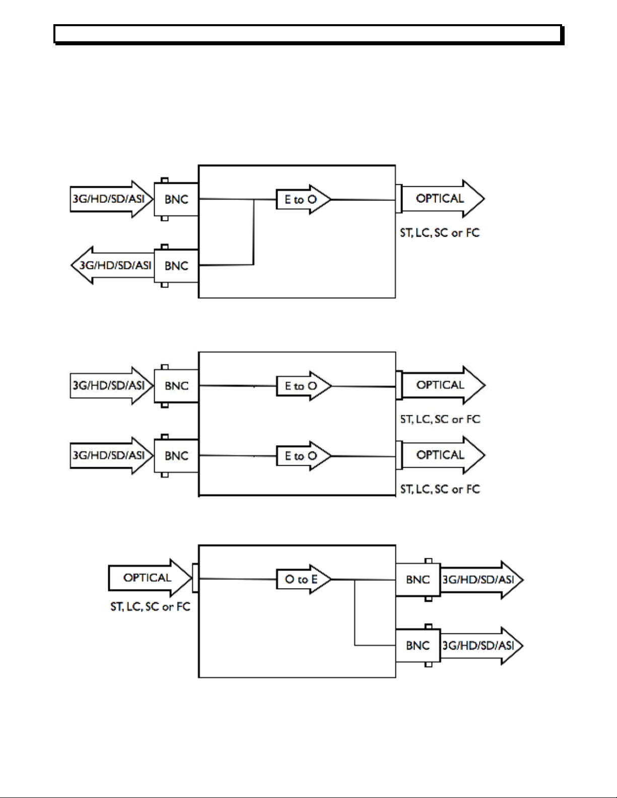
RECEIVER, HD3000-xRX
The receiver models, designated by model number HD3000-1RX or HD3000-2RX,
include 1 or 2 fiber IN optical connectors, depending on number of channels, and two
reclocked serial digital video OUT 75-Ohm BNC connectors. On the -1RX, the 2 BNC outputs
are a DA splitter, but on the -2RX, there is just a single BNC output for each channel due to
lack of rear panel space.
The receiver front panels include Rate LEDs with the same functionality as on the transmitter,
and a STATUS LED for optical signal level. In the receivers, the STATUS LED glows green if
the optical input signal is above 18dbm, yellow if between 15 and 18dbm, and red if below
15dbm. Note that this LED is not an indicator of signal integrity. The -2RX front panel will
have 2 groups of Rate and STATUS LEDs, one for each channel.
TRANSCEIVER, HD3000-TRX
The transceiver model, designated by model number HD3000-TRX, is essentially a -1TX and
a -1RX in the same enclosure, but without loopthru or DA connectors. It includes 1 fiber IN
and 1 reclocked fiber OUT optical connector, one reclocked serial digital video OUT 75-Ohm
BNC connector and one serial digital video IN 75 Ohm BNC connector. As on the transmitter,
only signals above 125 MBPS should be applied to the BNC input.
The -TRX front panel includes 2 groups of Rate and STATUS LEDs, one for the transmit
section and one for the receive section. Each includes Rate LEDs with the same functionality
as on the other models. The receive section has an Optical Signal Strength STATUS LED,
and the transmit section has a Carrier Detect STATUS LED, each with the same functionality
as described for the other models.
DROP AND REPEAT, HD3000-DR
The repeater model, designated by model number HD3000-DR, is essentially a -1RX with an
additional reclocked, regenerated optical loop thru output for repeating the optical signal
onward to other devices. It includes1 fiber IN and 1 fiber OUT optical connectors, and two re-
clocked serial digital video OUT 75-Ohm BNC connectors. As on the -1RX, the 2 BNC
outputs are a DA splitter.
The front panel of the –DR is functionally identical to that of the -1RX.
None of the models have a power LED because the STATUS LED(s) will be lit whenever
power is applied.
Ins ruc ion Manual, HD3000 Series
3
REV C, Feb 24, 2015
POWER REQUIREMENTS
The HD3000 Series operates from 115 or 230 VAC with a wall-mount power supply or 9 to 24
VDC @ >= 1A using a coaxial type connector (sleeve ground) on the rear panel labeled
POWER 9~24VDC. If desired, the units could be powered from a 12V battery.
INSTALLATION
The installation and start up of the HD3000 Series do not have special requirements. No
special sequence must be followed to connect and start up the units. RG59 or other 75 Ohm
Coax cable must be used for the BNC inputs and outputs and single mode fiber with the
selected proper connectors must be used for the fiber link. Optionally, multimode fiber can be
used with a shift patch on the transmitter, or if the units are ordered with MM optics, though
significantly reduced range performance is expected for this scenario. The HD3000 Series
come standard as stand-alone units. An optional rack-mounting kit is available to mount up to
6 units in a 1 Rack-unit or 1 ¾” by 19” rack space. The part number is –RM6.
SETTINGS FOR NON-SDI SIGNALS
The HD3000 series comes configured to satisfy the needs of most users.
This includes automatic reclocking and auto mute for SMPTE 3G, HD and SD signals and
support for DVB/ASI.
The factory setting is to auto mute the link when there is not a valid SMPTE signal present,
and to attempt to reclock any signals that are close to the standard SMPTE rates of 270,
1485 or 2970 MBPS. However, it is possible to pass other non SMPTE rates and digital
signals by setting dip switches located inside the units to the non-default values.
These settings are controlled by SW1. The settings are as follows:
In the -1TX, use settings for Ch 1. The Ch 2 settings are ignored. In the -1RX or -DR, use
settings for Ch 2. The Ch 1 settings are ignored. In the -TRX, Ch 1 refers to the T section
and Ch 2 to the R section. To access the switches, remove the 2 screws on the rear panel.
Slide the pcb out.
MAINTENANCE
There are no user serviceable parts or internal adjustments other than the switch
selections described above. As always, it is recommended that all optical fiber
connections be checked periodically for cleanliness and integrity. For repair and service,
please call the factory.
Sw 1
Func ion
Se ing (Defaul values in
Bold
)
1 Reclock Ch 1
O
ff
=
reclock
On = bypass
2 Reclock Ch 2
O
ff
=
reclock
On = bypass
3 Automute Ch 1
Off = never mu e
On = automute
4 Automute Ch 2
Off = never
mu e
On = automute
Ins ruc ion Manual, HD3000 Series
4
REV C, Feb 24, 2015
APPENDIX A. Block Diagrams
-1TX
-2TX
-1RX
Ins ruc ion Manual, HD3000 Series
5
REV C, Feb 24, 2015
-2RX
-TRX
-DR
Ins ruc ion Manual, HD3000 Series
6
REV C, Feb 24, 2015
APPENDIX B. Technical Specifica ions
Video
Bit Rates: 125 to 2970 MBPS
# of Ins/outs: 1 or 2 BNC(model dependent)
Impedance 75 Ohms
Level 800mV (peak to peak)
Standard: SMPTE 425M, 297M, 292M, 259M-C & DVB-ASI
Bit Error Rate (@-22dBm) 10
-11
Return Loss: >15 dB at 5 MHz - 1.485 GHz, >10 dB at 1.5 GHz to 3 GHz
Jitter(wideband) < 0.3 UI
Rise/Fall times <120psecs
Op ical
Wavelengths T : 1310nm or CWDM R : 1100~1600nm
Optical Connector ST, SC or LC
Optical Source FP laser or CWDM DFB
Optical Detector PIN Diode
T Output -7 Standard (0 DFB)
R Sensitivity -22 dBm
Link Margin 15 to 22 dB (up to 40km)
Fiber Type Multimode or Singlemode, Singlemode recommended
Environmen al/ Elec rical
Power: 9-24 VDC
Consumption <5 Watts
Temperature: 0 to +70C
Humidity 0-95% RH non-condensing
Dimensions 2.75 x 1.125 x 5 inches
Weight 7 oz.
Display: LEDs for Power, Rate, Carrier Detect, Optical Signal Level
Cable Leng h Equalized (w/Belden 1694A)
3 GBPS: >120m
1.485 GBPS: >150m
143-360 MBPS: >350m
Specifications are subject to change without notice.

This manual suits for next models

6

Other MultiDyne Media Converter manuals

MultiDyne FMX-GE-1000 User manual

MultiDyne

MultiDyne FMX-GE-1000 User manual

MultiDyne MD9200-DEC User manual

MultiDyne

MultiDyne MD9200-DEC User manual

MultiDyne FMX-100 User manual

MultiDyne

MultiDyne FMX-100 User manual

MultiDyne MD9200-ENC User manual

MultiDyne

MultiDyne MD9200-ENC User manual

MultiDyne MD9200-DEC Quick guide

MultiDyne

MultiDyne MD9200-DEC Quick guide

Popular Media Converter manuals by other brands

Extron electronics DVS 304 user guide

Extron electronics

Extron electronics DVS 304 user guide

ALCHEMIST TS-D-2 instruction manual

ALCHEMIST

ALCHEMIST TS-D-2 instruction manual

Advantech ADAM-4561-CE user manual

Advantech

Advantech ADAM-4561-CE user manual

ICP DAS USA I-7540D quick start

ICP DAS USA

ICP DAS USA I-7540D quick start

Midian VS-110-IC1 Installation guides

Midian

Midian VS-110-IC1 Installation guides

Axis Q7900 Rack installation guide

Axis

Axis Q7900 Rack installation guide

Mitsubishi Electric PAC-SJ95MA-E installation manual

Mitsubishi Electric

Mitsubishi Electric PAC-SJ95MA-E installation manual

MDR Electronics MX-1225 manual

MDR Electronics

MDR Electronics MX-1225 manual

Parkside 109819 Operation and safety notes

Parkside

Parkside 109819 Operation and safety notes

Pyle view PLVSC404 Operation manual

Pyle view

Pyle view PLVSC404 Operation manual

NAD VISO 1BT owner's manual

NAD

NAD VISO 1BT owner's manual

Trix 66837 manual

Trix

Trix 66837 manual

Roland SRC-2 owner's manual

Roland

Roland SRC-2 owner's manual

Generic HDV-337A user manual

Generic

Generic HDV-337A user manual

Tevion Music/Audio Converter user manual

Tevion

Tevion Music/Audio Converter user manual

Meitner Audio MA-1 Manual guide

Meitner Audio

Meitner Audio MA-1 Manual guide

Steren 208-140 instruction manual

Steren

Steren 208-140 instruction manual

Pro-Ject Audio Systems DAC Box S USB Instructions for use

Pro-Ject Audio Systems

Pro-Ject Audio Systems DAC Box S USB Instructions for use

manuals.online logo
manuals.online logoBrands
  • About & Mission
  • Contact us
  • Privacy Policy
  • Terms and Conditions

Copyright 2025 Manuals.Online. All Rights Reserved.