MultiDyne MD9200-DEC Quick guide

10 NEWTON PLACE
HAUPPAUGE, NY 11788 USA
(877) 685-8439 / (516) 671-7278 / FAX (516) 671-3362
www.multidyne.com
CONFIGURATION AND INSTALLATION MANUAL
MD9200-DEC
&
MD9200-DEC-OG
OTT Streaming Media Decoders

MD9200-DEC Software Manual
MultiDyne © 2020
1
Table of Contents
Logging into the User Interface 3
Gigabit Ethernet (GigE) port values 3
MD9200-DEC Header 4
Message Envelope 5
STATUS 6
The STATUS Sub Tab 6
Edit Video 8
Edit Audio 8
The METADATA Sub Tab 10
The STATISTICS Sub Tab 10
STREAM 11
The INPUT Sub Tab 11
The OUTPUT Sub Tab 13
Stream Fields 14
MEDIA 17
The MEDIA Sub Tab 17
Manage Media 18
The PLAYLISTS Sub Tab 19
TRANSCODE 21
The OUTPUTS Sub Tab 21
The VIDEO Sub Tab 24
The AUDIO Sub Tab 26
The STATISTICS Sub Tab 28
DISPLAY 29
The FORMAT Sub Tab 29

MD9200-DEC Software Manual
MultiDyne © 2020
3
Logging into the User Interface
The MD9200-DEC uses a modern HTML5-embedded Web server for user configuration. Users
can connect to the MULTIDYNE device via Gigabit Ethernet (GigE) port 1 or GigE port 2. GigE
port 1 is factory defaulted to DHCP and GigE port 2 is factory defaulted to 192.168.2.7.
Gigabit Ethernet (GigE) port values
Gigabit Ethernet Port
Configuration
GigE 1
DHCP
GigE 2
192.168.2.7
Users are presented with the MULTIDYNE login screen when
accessing the User interface, to which the username and
password may be entered (3). Currently usernames cannot be
modified.
Username: 9200
Password: DEC
LEFT: The unit serial number (1) is displayed along the top of
the login modal, and the current firmware version for the unit
(4) is displayed along the bottom. To the right of the unit serial
number, a Help link (2) may be accessed. This link will take
users to the Help page, which provides more information
about connecting to the UI, as well as unit technical
information about the unit.
Once logged in, the MULTIDYNE unit UI is divided into two
sections: the header, which is visible on all tabs, and the body,
where the content depends on which tab is in use.

MD9200-DEC Software Manual
MultiDyne © 2020
4
MD9200-DEC Header
ABOVE: The current tab in use is emboldened in blue.
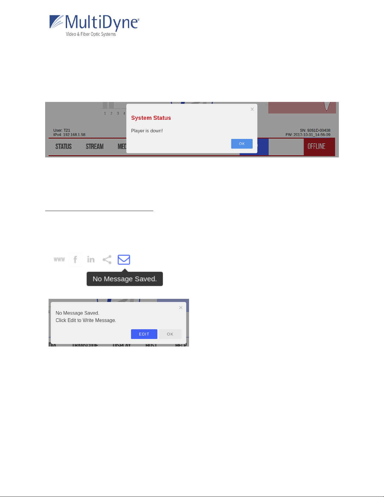
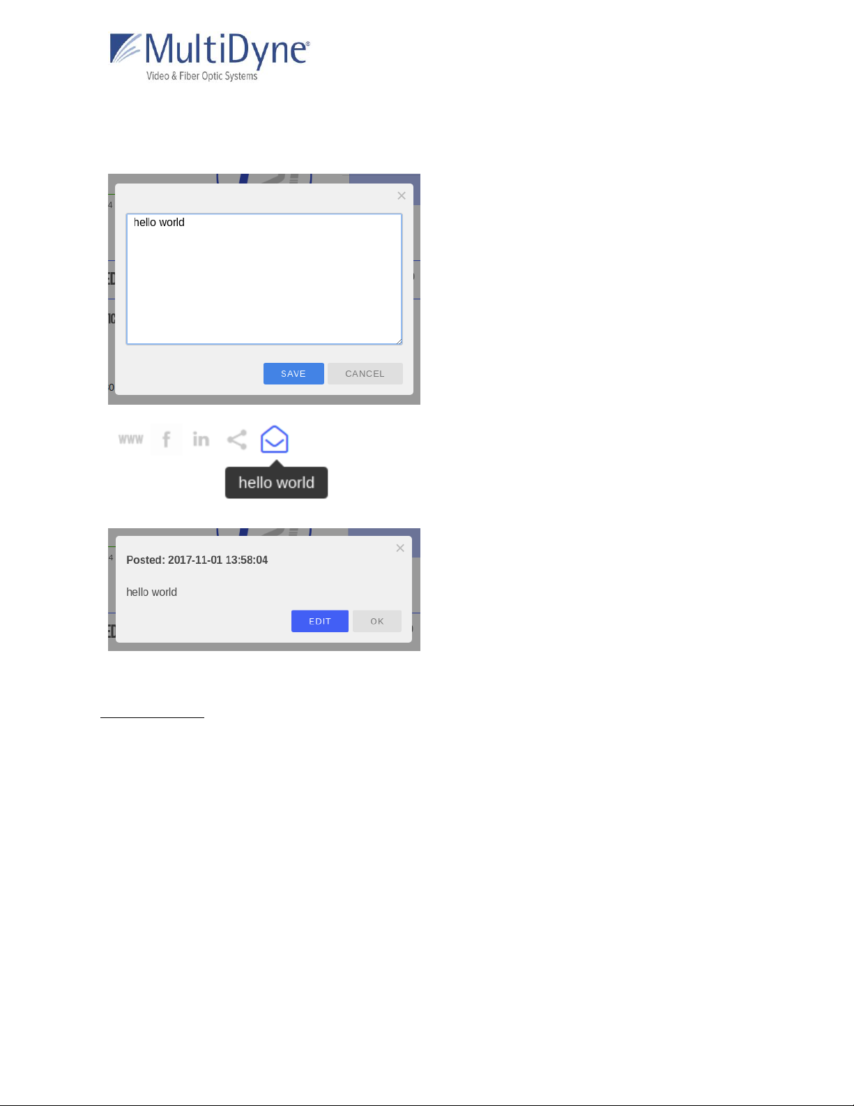
Along the top left of the page are links to publicly accessible MULTIDYNE web pages, including
the main website, Facebook, LinkedIn, MULTIDYNE Finder application in the Chrome store, and a
message envelope (1).
The product type is displayed in the top center (2).
A thumbnail (4) is generated every five seconds to reflect the media being decoded by the unit.
The Audio Group graph (5) reflects levels of the channels as they update.
The mini statistics graphs (6) to the right display the rate of Mbps and, depending on the
protocol, packets. Clicking the graph will resolve to the STATISTICS sub tab.
Along the top right of the page, system time (3) is displayed and updated per second, directly
above a logout link.
The serial number and current firmware version of the unit (7) are displayed along the bottom
right of the header, and the current IPv4 address of the unit on the left (8).
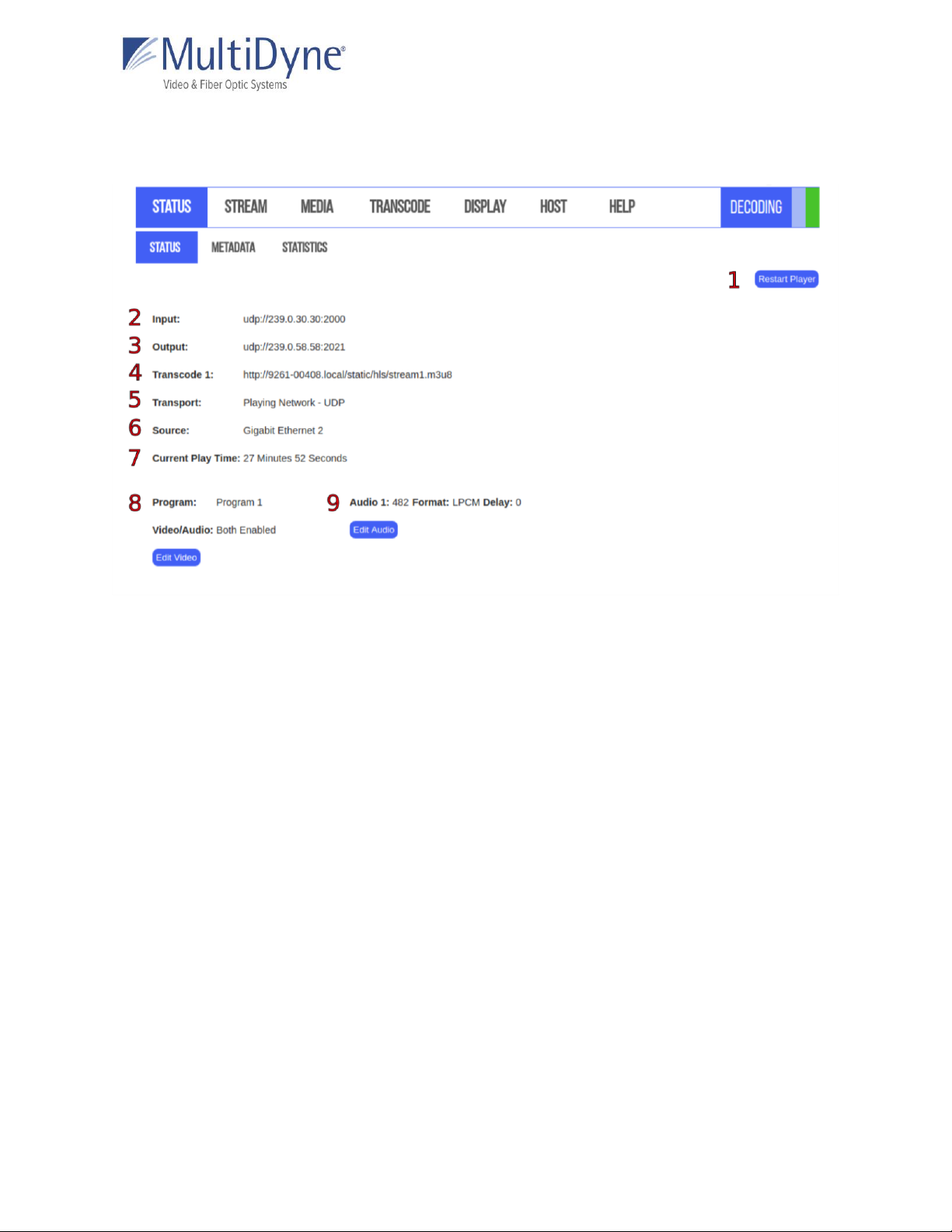
When a transcode is running a blinking status bar will be visible for each one (10).
The status of the decoder is displayed in the menu (9) and will change color as conditions
change.
●When the player is up, or the UI is able to connect to and interact with the player, the
box (9) will be blue and display DECODING. The player status (11) will be green.
●When the UI is experiencing difficulty interacting with the player the player status (11)
will change to yellow, the status box (9) will do the same, displaying LISTENING. Both
will resolve to blue or red after a short period of time.
●When the player is down, or cannot be connected to via the UI, the player status (11)

MD9200-DEC Software Manual
MultiDyne © 2020
5
and the status box (9), displaying OFFLINE, will turn red. When this occurs, a window
(pictured below) appears informing users of the issue, shown below.
Users may click the OK button to exit the window, or it will disappear automatically when the
issue is resolved.
Message Envelope
The envelope icon can be used to leave messages specific to how the unit is set up or what the
unit is doing.
Hovering over the message icon when
nothing has been saved will show this
message or simply “message.” Click to save a
message.
The first modal usually is a preview, or will
give direction on how to add your message.

MD9200-DEC Software Manual
MultiDyne © 2020
6
Enter your message and click save to apply
your changes.
Now hovering over the message icon will
preview your message.
Clicking on the envelope will show the
message and a timestamp of when it was
posted.
STATUS
The STATUS Sub Tab
After successfully logging in to a unit, users are brought to the STATUS tab. Within the STATUS
tab, information about the unit’s current status is displayed, and program settings can be
modified.

MD9200-DEC Software Manual
MultiDyne © 2020
7
ABOVE: The Restart Player button (1) will restart the current player without rebooting the
device. Click OK on the resulting modal to begin the process.
The Input (2) displays the decoder’s current input path.
The Output (3) displays the decoder’s current output path.
The Transcode (4) displays the decoder’s current transcode path. Each transcode that is
outputting will display on this tab.
The Transport (5) refers to the type of media being decoded; this can be a network
stream, media file on the unit, or playlist.
The Source (6) may be Gigabit Ethernet 1, Ethernet 2, or DISK.
The Current Play Time (7) is the amount of time the unit has been decoding the particular
media.
The Video (8) information displays the Program and Video/Audio. These settings can be
changed by clicking the Edit Video button.
The Audio (9) information displays the decoder’s current Audio pids, Format and Delay which
can be edited by clicking the Edit Audio button.

MD9200-DEC Software Manual
MultiDyne © 2020
8
Edit Video
The Program determines which program number
to play; audio options available vary depending on
the media being decoded.
The Video/Audio determines whether the video,
audio, or both is enabled. Clicking the SAVE button
sets the changes.
Edit Audio
Audio 1-4 determine the
current audio pid being
enabled/decoded. Pids
need to be set in
consecutive order. Format
determines the audio
channel output format;
options include LPCM
(Linear Pulse Code
Modulation), PASS SMPTE
(Passthrough), and PASS ICE
(Passthrough). Delay sets
the audio offset, in
milliseconds. Clicking the
SAVE button sets the
changes. Editing Audio Pid
1 or Audio 1 Format alone
does not require the play
path to be reacquired.

MD9200-DEC Software Manual
MultiDyne © 2020
9
When more than one Audio Pid
is available they will be
displayed on the STATUS sub
tab.

MD9200-DEC Software Manual
MultiDyne © 2020
10
The METADATA Sub Tab
Shows any available metadata, by program, for an input stream being decoded. Can have
information for as many programs as the stream contains.
The STATISTICS Sub Tab
ABOVE: The STATISTICS sub tab contains information about the input stream (1) updated in

MD9200-DEC Software Manual
MultiDyne © 2020
11
intervals. The information available depends on what protocol is being decoded. All streams
yield Mbps for the Mbps graph (2) but the Packets graph (3) will be available for certain
protocols like UDP/RTP and Zixi streams.
STREAM
The INPUT Sub Tab
ABOVE: The Ping Address (1) may be used to determine whether or not a device, such as a
source encoder, is on the same network as the MD9200-DEC. To use it, enter the IP address of
the device in question. An Up or Down will be displayed next to this field indicating the status of
the device.
The History (2) dropdown has the last ten streams that the unit successfully decoded. Click the
Clear History button to erase them. This will halt decoding and restart the current player
process without rebooting the device.

MD9200-DEC Software Manual
MultiDyne © 2020
12
Choosing a different protocol will generate an appropriate form (4). Make your changes and
then click Apply.
Play Control buttons (3) start, stop, or play the next path if there are fallbacks applied. When
Fallbacks are applied the blue arrow (5) becomes visible on the currently decoding stream.
Clicking the blue plus button next to Fallback (9) will add up to three forms to apply a fallback.
If a fallback source is configured, the MD9200-DEC unit will attempt to decode fallback
sources in descending order until one is able to be successfully decoded. If the primary
source stream becomes available after the player has switched to a fallback, the player will
not be able to re-acquire the primary stream until the user re-applies the primary stream
settings. Remove the fallback by clicking the red X button to the left.
Dejitter (6) determines the size of the dejitter buffer in milliseconds to allow for smoother
decoding oversaturated networks and distances. A larger value corresponds to greater latency,
so the number should not be higher than required for smooth decoding of the current source
stream. The default setting of 33 milliseconds is sufficient for most networks.
Null Packet Detection (7) Software demux is normally used in null stripped sources. Setting to
“disable”, disables and forces hardware demuxer.
IGMP Filter Mode (8) settings can also be configured to allow for an inclusive or exclusive list
of stream sources. If using a filter, the IGMP filter list will be shown. This can be used on
networks with streams coming from many different sources, in order to prevent overlap of
stream addresses. For example, if two encoders are both outputting a UDP stream at
udp://239.0.1.125:2000, and it is known that the desired stream is coming from the
encoder at address 192.168.2.7, an inclusive IGMP source list can be configured as
demonstrated above for that specific encoder’s IP address.

MD9200-DEC Software Manual
MultiDyne © 2020
13
Clicking the Regenerate button will
create a new RTMP Stream ID and
replace the content in the field if
there is any. Click the Copy Path
button to open a modal with the full
HLS path.
The OUTPUT Sub Tab
The Output Stream is a turnaround of the input.

MD9200-DEC Software Manual
MultiDyne © 2020
14
Stream Fields
as of FW: 2017-10-31_14-56-09
FIELD NAME
DESCRIPTION
USE CASE
Protocol:
This determines the type of stream
network protocol to transmit and/or
receive. Each field is named for its given
type, with some exceptions; the Custom
protocol allows users to enter their own
form of address, which will be parsed and
utilized by the player. Custom is used with
HLS and RTSP.
This field appears for every Protocol type.
Interface:
This field represents the physical ethernet
port streams are received or transmitted
on. The available options are Gig 1 and
Gig 2.
Input/Output/Transcode: UDP, RTP, TCP
Address:
This field represents the IP address the
stream will be decoding.
No leading zeros in IPv4 addresses as we
are not constrained to octals.
Input/Output/Transcode: UDP/RTP, SRT
(Caller, Rendezvous), TCP, ZIXI (Pull, Feeder)
Port:
This field represents the ethernet port
number for the stream.
Input/Output/Transcode: UDP/RTP, SRT
(Caller, Listener, Rendezvous), TCP, ZIXI (Port,
Accept, Feeder)
MTU:
Maximum Transmission Unit is the size
of the largest network layer protocol data
unit that can be communicated in a single
network transaction.
Input/Output/Transcode: SRT (Caller,
Listener, Rendezvous)
Encryption /
Password or Key:
Choose the encryption type, AES 128 (32
char) or AES 256 (64 char).
Input/Output/Transcode: SRT (Caller,
Listener, Rendezvous)
Output/Transcode: ZIXI Feeder
Timeout:
Period in seconds that the connection will
try before it hangs up. If left blank factory
default is 10 seconds.
Input/Output/Transcode: SRT (Caller,
Listener, Rendezvous)
Latency:
This field represents the specified latency
time for sending packets of data, given in
Input/Output/Transcode: SRT (Caller,
Listener, Rendezvous), ZIXI (Pull, Feeder)

MD9200-DEC Software Manual
MultiDyne © 2020
15
milliseconds. The default latency value is
3000 milliseconds.
Server Address:
IP address of the MULTIDYNE FASP
Server.
Input: FASP Client
Target Rate:
Overall stream rate, matches the transport
rate of the encoder profile.
Input: FASP Client
Remote ID /
Password:
These fields represent the Remote ID and
password of a Zixi broadcaster, which may
be optional depending on the desired
stream.
Input: ZIXI Pull
Stream ID:
This field represents the stream ID of a Zixi
broadcaster and an RTMP Server. Clicking
the Regenerate button will create a new
RTMP Stream ID and replace the content
in the field if there is any.
Input: ZIXI Pull, RTMP Server
Output/Transcode: Zixi Feeder
URL:
This field represents the URL address of a
stream.
The RTMP fields is tied to its respective
Protocol, while the Custom field allows
users to enter an unspecified stream
address that the decoder will parse.
The HLS second field can be changed to a
personalized Stream ID. Copy the whole
path to receive the stream.
Input: RTMP (Client, Server), Custom
Transcode: HLS
TTL:
Time to Live default number of hops
between devices, default value is 64.
Output/Transcode: UDP/RTP, SRT (Caller,
Rendezvous)
Traffic Shaping:
Buffers the output data to ensure constant
intervals between packets.
Output/Transcode: UDP/RTP
Bandwidth
Overhead:
Percentage used for forward error
correction.
Output/Transcode: SRT (Caller, Rendezvous)
ToS:
Type of Service is the payload type for
prioritizing traffic through routers.
Output/Transcode: SRT (Caller, Rendezvous)
Max Bitrate:
The rate of the transport output should be
set equal or greater than the total output
of the device.
Recommended to set 20% higher.
Output/Transcode: ZIXI Feeder

MD9200-DEC Software Manual
MultiDyne © 2020
16
Min Bitrate:
Setting a value enables Adaptive Bitrate.
Output/Transcode: ZIXI Feeder
Output Location:
List of available directories.
Output/Transcode: File
See the MULTIDYNE Decoder Stream Configuration Guide for more information.

MD9200-DEC Software Manual
MultiDyne © 2020
17
MEDIA
The MEDIA Sub Tab
ABOVE: Play Control buttons (1)
rewind, start, pause, stop, play the next
path, or fast forward. If a video from
media is being decoded, will cycle
through media folder.
Load button (2) will start decoding a
video and then cycle through the
folder on loop. The Filter (3) searches
the titles of the media loaded on the
unit. Clicking the Manage Media
button (4) will reveal tools to upload
and edit media. When hovering over
the thumbnail the Analyze button (6)
shows. Clicking it brings up a modal
with metadata for that file, shown to
the LEFT.

MD9200-DEC Software Manual
MultiDyne © 2020
18
Manage Media
ABOVE: Choose a file from your computer and click Upload (1) to copy it to the unit. Clicking
the Pencil icon (2) brings up the Rename File modal (bottom left) and the red X icon (3) brings
up the delete file modal (bottom right).

MD9200-DEC Software Manual
MultiDyne © 2020
19
The PLAYLISTS Sub Tab
BELOW: See the Media Play Control for details (1). Playlists are saved in the Playlists box (2),
click them to highlight and show contents in the Playlist Media box (3). Double click a playlist
title to begin playing.
While the playlist is highlighted click the buttons (4) under the Playlists box to Edit, Rename, or
Delete the playlist. Add a new playlist at any time.
Other manuals for MD9200-DEC
1
This manual suits for next models
1
Table of contents
Other MultiDyne Media Converter manuals
Popular Media Converter manuals by other brands

AMX
AMX NMX-ENC-1100 instruction manual

Danfoss
Danfoss VLT AutomationDrive FC 300 operating instructions

OT Systems
OT Systems FT410DB Series Installation and operation manual

Panasonic
Panasonic AJ-YDX30G operating instructions

Nikon
Nikon WC-E80 instruction manual

TR-Electronic
TR-Electronic CEH582M-8192/32768 EPN DMS 12H7 KRF Assembly instructions