Multimetrix XA 3051 User manual
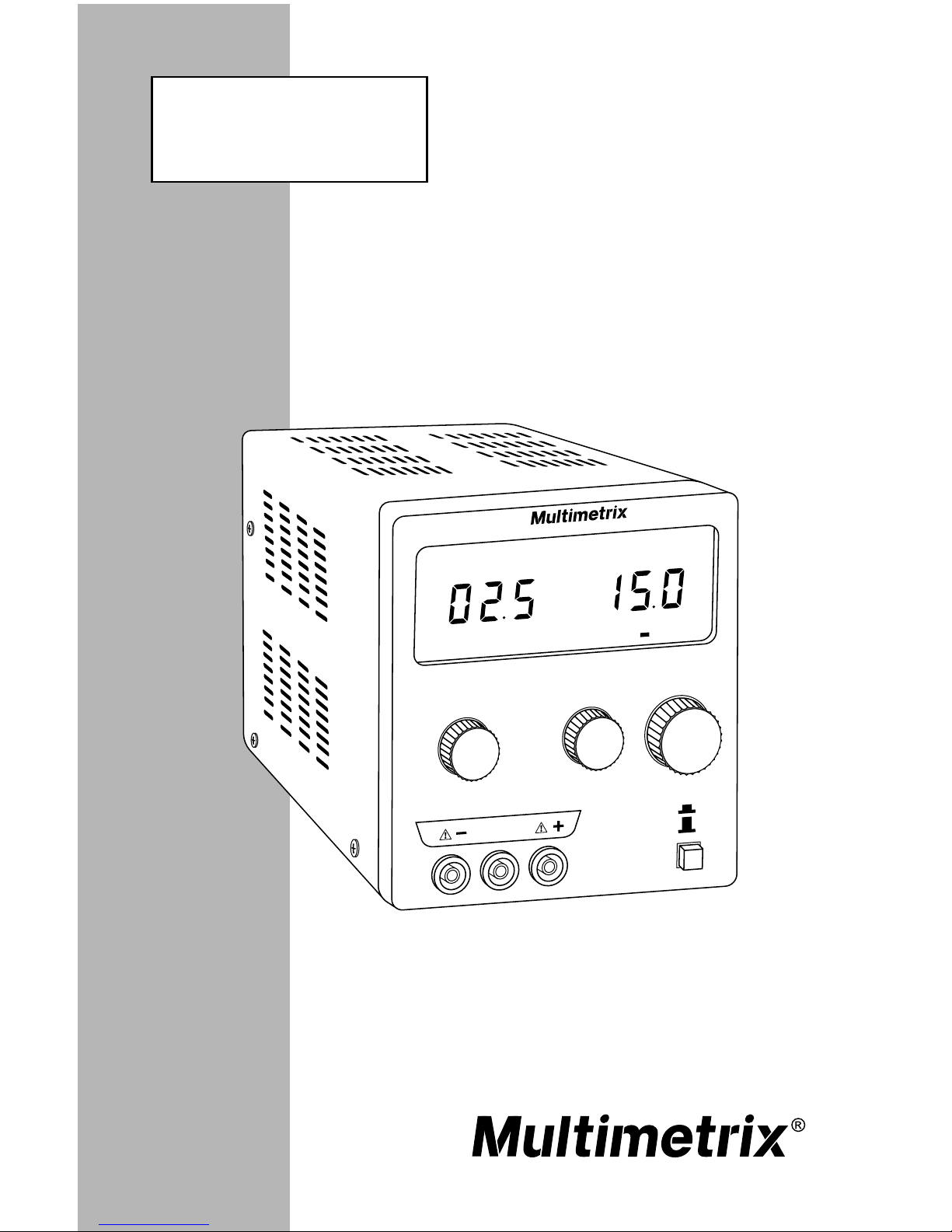
n SINGLE OUTPUT
POWER SUPPLIES
XA 1525
XA 3051
ENGLISH User Manual

Table of Contents
1. INTRODUCTION ..............................................................2
Warning.............................................................................................2
1.1 International Electrical Symbols................................................3
1.2 Receiving Your Shipment..........................................................3
1.3 Ordering Information.................................................................3
2. PRODUCT FEATURES .....................................................4
2.1 Control Features .......................................................................4
3. SPECIFICATIONS ............................................................5
3.1 Electrical Specications ............................................................5
3.2 Mechanical Specications ........................................................5
3.3 Safety Specications ................................................................5
4. OPERATION ....................................................................6
4.1 Before Using the Instrument .....................................................6
4.2 Operating Instructions...............................................................7
4.2.1 Setting the Supply Voltage............................................7
4.2.2 Voltage and Current Adjustment ...................................7
4.2.3 Using the unit as a Current Constant Source ...............8
4.2.4 Using the unit as a Constant Voltage Source ...............8
5. MAINTENANCE ...............................................................9
5.1 Warning ....................................................................................9
5.2 Fuse Replacement....................................................................9
5.3 Cleaning....................................................................................9
5.4 Storage .....................................................................................9
Repair and Calibration...........................................................................10
Technical and Sales Assistance ............................................................10
Limited Warranty ................................................................................... 11
Warranty Repairs...................................................................................11
2
Single Output Power Supplies Models XA 1525 / XA 3051
CHAPTER 1
INTRODUCTION
Warning
These safety warnings are provided to ensure the safety of
personnel and proper operation of the instrument.
• Read the instruction manual completely and follow all safety
information before operating this instrument.
• Only use the leads that are supplied with the instument.
Before using them, always check that they are in perfect
working order.
• Any break in the protective conductor, inside or outside the
instrument, or disconnection of the protective earth terminal
may make the instrument dangerous. Intentional breaking is
prohibited.
• When this instrument is supplied via an auto-transformer,
in order to reduce the external voltage, make sure that the
common terminal is connected to the neutral (earthed pole)
of the supply circuit.
• The plug should only be inserted into a socket equipped
with a grounding contact. The safety connection must not
be broken by use of an extension lead without a protective
conductor.
• When the required voltage and current parameter values are
unknown, start by using the lowest values.
• Before disconnecting the connection leads of the circuit
being tested, make sure that the power supply is switched
off. This prevents the creation of break or closure extra-cur-
rents which may melt the fuse at high currents.
• Never exceed a total output of 60V peak in relation to the
earth (common mode).
• The instrument must be placed in a ventilated room. Take
care not to obstruct the ventilation holes.

Single Output Power Supplies Models XA 1525 / XA 3051
3
1.1 International Electrical Symbols
This symbol signies that the instrument is protected by double or
reinforced insulation. Use only specied replacement parts when
servicing the instrument.
This symbol on the instrument indicates a WARNING and that
the operator must refer to the user manual for instructions before
operating the instrument. In this manual, the symbol preceding
instructions indicates that if the instructions are not followed, bodily
injury, installation/sample and product damage may result.
Risk of electric shock. The voltage at the parts marked with this
symbol may be dangerous.
1.2 Receiving Your Shipment
Upon receiving your shipment, make sure that the contents are consistent
with the packing list. Notify your distributor of any missing items. If the
equipment appears to be damaged, le a claim immediately with the car-
rier and notify your distributor at once, giving a detailed description of any
damage. Save the damaged packing container to substantiate your claim.
Do not use an instrument that appears to be damaged.
1.3 Ordering Information
Model XA 1525 ......................................................... Cat. #MMX-XM1525
Includes DC Power Supply, 120V US Power Supply Cord and User Manual.
4
Single Output Power Supplies Models XA 1525 / XA 3051
CHAPTER 2
PRODUCT FEATURES
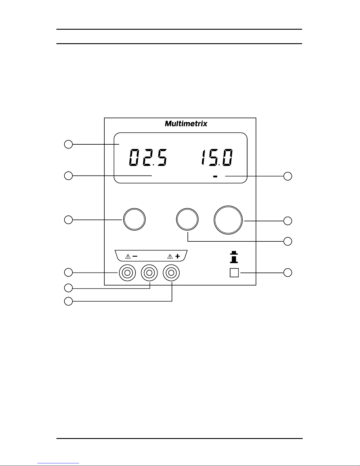
2.1 Control Features
1. Voltage and Current LED Display
2. Constant Current (CC) Indicator
3. Current Adjustment Potentiometer
4. (-) Output Terminal
5. Ground Terminal
6. (+) Output Terminal
7. Constant Voltage (CV) Indicator
8. “Coarse” Voltage Adjustment
9. “Fine” Voltage Adjustment
10. ON/OFF Power Switch

Single Output Power Supplies Models XA 1525 / XA 3051
5
CHAPTER 3
SPECIFICATIONS
3.1 Electrical Specications
XA 1525 XA 3051
Voltage Output 0 to 15VDC 0 to 30VDC
Current Output 0 to 2.5A 0 to 5A
Display Accuracy Volts: ±1% + 2cts
Amps: ±2% + 2cts
Line Regulation CV: ±0.05% ± 5mV
CC: ±0.5% ± 3mA
Power Supply 115VAC ± 10%, 230VAC ± 10%, 50/60Hz
3.2 Mechanical Specications
Display: Two
3-Digit Red LED Displays
Voltage & Current displayed simultaneously on separate displays
CV or CC operation indication with LED
Dimensions: 10.6 x 5.2 x 6.3" (270 x 132 x 160mm)
Weight: 14 lbs (6.3kg)
3.3 Safety Specications
Immunity: EN 55024
Emission: EN 55022 – EN 61000-3-2 – EN 61000-3-3
Cat II, 300V, Pollution Degree 2
6
Single Output Power Supplies Models XA 1525 / XA 3051
CHAPTER 4
OPERATION
4.1 Before Using the Instrument
• When the required voltage and current parameter values are not
known, start by using the lowest values.
• Before disconnecting the leads of the circuit under test, make
sure that the power supply is turned off. This prevents the cre-
ation of break or closure extra-currents which may melt the fuse
at high currents.
• Never exceed a total output of 60V peak in relation to the ground.
• The instrument must be placed in a ventilated room. Do not
obstruct the ventilation holes.
• Before opening the instrument, disconnect it from all sources of
electric current and from the measuring circuits; make sure that
you are not charged with static electricity, which could irreparably
damage the instrument’s internal components.
When the instrument is open, some of the internal capaci-
tors may be dangerous, even once the instrument has been
powered down.
In the event of faults or abnormal constraints, turn the
instrument OFF and do not use it until it has been checked.

Single Output Power Supplies Models XA 1525 / XA 3051
7
4.2 Operating Instructions
4.2.1 Setting the Supply Voltage
To set the supply voltage
from 115V to 230V or from
230V to 115V, slide the
switch to the appropriate
setting on the rear panel
of the instrument.
4.2.2 Voltage and Current Adjustment
• Turn the Power Supply off.
• Connect the load as shown above.
• Turn the Current and Voltage output to zero (the left).
• Turn the Power Supply on.
• Adjust the Current and Voltage as needed.
• Current and Voltage output level will be indicated by LEDs.
• Adjust the output to the desired value.

8
Single Output Power Supplies Models XA 1525 / XA 3051
4.2.3 Using the unit as a Current Constant Source
• Turn the Power Supply off.
• Turn the Voltage and Fine adjustments clockwise (right turn) all the
way to the end, and the Current Adjustment Potentiometer counter-
clockwise (left turn) to the end (to zero).
• Then connect the load.
• Turn the Power Supply on.
• Turn the Current Adjustment Potentiometer to get desired current.
• The CC LED indicator should be on.
4.2.4 Using the unit as a Constant Voltage Source
• Turn the Power Supply off.
• Set the Current Adjustment Potentiometer to its maximum value.
• Turn the unit on and adjust the Voltage Coarse and Fine adjustments.
• To adjust the current limit, turn the Power Supply off and short-circuit
the (+) and (-) outputs.
• Turn the Power Supply back on, then turn the Current Adjustment
Potentiometer to the desired limit current.
• Turn the Power Supply off. Remove the short-circuit and connect the
load.
• Turn the Power Supply back on.
• The CV LED indicator should be on.
To get a more accurate measuring value, you should calibrate by external
circuit with precision measuring instrument.

Single Output Power Supplies Models XA 1525 / XA 3051
9
CHAPTER 5
MAINTENANCE
5.1 Warning
• For maintenance use only specied factory replacement parts.
• To avoid electrical shock, do not attempt to perform any servicing
unless you are qualied to do so.
• To avoid electrical shock and/or damage, do not get water or
other foreign agents into the case. Turn the instrument OFF and
disconnect the unit from all the circuits before opening the case.
5.2 Fuse Replacement
The fuse protects the primary coil of the power supply transformer against
line voltage errors. The fuse location is on the rear panel.
Before opening the power supply to change the fuse, you must disconnect
the leads and power cord.
Only use a fuse of the following type:
• Model XA 1525 - T 1.5A / 250V
• Model XA 3051 - T 2A / 250V
5.3 Cleaning
• Disconnect the instrument, then clean it with a cloth lightly moist-
ened with soapy water.
• Wipe with a clean dry cloth. Make sure it has completely dried
before use.
• Do not use abrasives or solvents.
5.4 Storage
An abrupt change in the ambient temperature may lead to
condensation inside the instrument and cause short circuits.
Let the power supply stabilize in temperature before use.
• To ensure proper operation, wait for the instrument to return to
normal measuring conditions if it has been stored in extreme
environmental conditions for a long period of time.

10
Single Output Power Supplies Models XA 1525 / XA 3051
Repair and Calibration
To ensure that your instrument meets factory specications, we recommend
that it be scheduled back to our factory Service Center at one-year intervals
for recalibration, or as required by other standards or internal procedures.
For instrument repair and calibration:
You must contact our Service Center for a Customer Service Authorization
Number (CSA#). This will ensure that when your instrument arrives, it will be
tracked and processed promptly. Please write the CSA# on the outside of the
shipping container. If the instrument is returned for calibration, we need to
know if you want a standard calibration, or a calibration traceable to N.I.S.T.
(Includes calibration certicate plus recorded calibration data).
Ship To: Multimetrix®
15 Faraday Drive
Dover, NH 03820 USA
Tel: (800) 945-2362 (Ext. 360)
(603) 749-6434 (Ext. 360)
Fax: (603) 742-2346 or (603) 749-6309
(Or contact your authorized distributor)
Costs for repair, standard calibration, and calibration traceable to N.I.S.T. are
available.
NOTE: You must obtain a CSA# before returning any instrument.
Technical and Sales Assistance
If you are experiencing any technical problems, or require any assistance with
the proper operation or application of your instrument, please call, mail, fax or
e-mail our technical support team:
Multimetrix®
200 Foxborough Boulevard
Foxborough, MA 02035 USA
Phone: (800) 343-1391
(508) 698-2115
Fax: (508) 698-2118
www.multimetrix.us
NOTE: Do not ship Instruments to our Foxborough, MA address.

Single Output Power Supplies Models XA 1525 / XA 3051
11
Limited Warranty
The Model XA 1525 and XA 3051 are warranted to the owner for a period of
one year from the date of original purchase against defects in manufacture.
This limited warranty is given by Multimetrix®, not by the distributor from whom
it was purchased. This warranty is void if the unit has been tampered with,
abused or if the defect is related to service not performed by Multimetrix®.
For full and detailed warranty coverage, go to www.multimetrix.us. The
warranty information is located in our customer service section.
What Multimetrix® will do:
If a malfunction occurs within the one-year period, you may return the
instrument to us for repair, provided you submit a proof of purchase.
Multimetrix® will, at its option, repair or replace the faulty material.
Warranty Repairs
What you must do to return an Instrument for Warranty Repair:
First, request a Customer Service Authorization Number (CSA#) by phone
or by fax from our Service Department (see address below), then return the
instrument along with the signed CSA Form. Please write the CSA# on the
outside of the shipping container. Return the instrument, postage or shipment
pre-paid to:
Multimetrix®
Service Department
15 Faraday Drive • Dover, NH 03820 USA
Tel: (800) 945-2362 (Ext. 360)
(603) 749-6434 (Ext. 360)
Fax: (603) 742-2346 or (603) 749-6309
Caution: To protect yourself against in-transit loss, we recommend you
insure your returned material.
NOTE: You must obtain a CSA# before returning any instrument.

07/04
99-MAN 100009 v1
Multimetrix® a division of Chauvin Arnoux®, Inc.
15 Faraday Drive • Dover, NH 03820 USA
www.multimetrix.us
Table of contents
Other Multimetrix Power Supply manuals

Popular Power Supply manuals by other brands


Thermal Dynamics
Thermal Dynamics 38 Cutmaster instruction manual

VOLTCRAFT
VOLTCRAFT USPS-1000N operating instructions

Emerson
Emerson Universal-R Installing and operating instructions

TELECO AUTOMATION
TELECO AUTOMATION AL-24-150WNT instructions

GW Instek
GW Instek GPS-1830 user manual

EFOY
EFOY EFOY Pro 600 manual

Agilent Technologies
Agilent Technologies E3634A Service guide

Alpha Technologies
Alpha Technologies APP 9022S Installation and operation manual

B+K precision
B+K precision 9140 Series user manual

Whelen Engineering Company
Whelen Engineering Company UPS69024 installation guide

I-Tech
I-Tech IT6900 Series user manual

Kikusui
Kikusui PAT-T Series manual