BEHLMAN BL10000 Series Use and care manual

USER'S GUIDE AND
TECHNICAL REFERENCE
AC SOURCE
BEHLMAN MODEL BL10000 SERIES
PART NUMBER:______________
MODEL _____________________
FOR SERVICE ASSISTANCE
CONTACT BEHLMAN
CUSTOMER SERVICE DEPARTMENT
PHONE TOLL FREE 1-800-874-6727
OR WRITE
BEHLMAN
CUSTOMER SERVICE DEPARTMENT
80 CABOT COURT
HAUPPAUGE, NY 11788
PHONE: (631) 453-0410
FAX : (631) 951-4341
FOR SALES INFORMATION:
PHONE: (631) 435-0410
USA : (800) 874-6727
FAX : (631) 951-4341
DATE:07/11 REV. B

CLAIM FOR DAMAGE IN SHIPMENT
Under the FOB factory terms of sale, ownership and responsibility are transferred to the customer when the
equipment leaves the factory. Each Behlman equipment is shipped from the factory in proper operating condition.
Immediately upon receiving equipment, unpack and inspect it for evidence of damage incurred in shipment. File
a claim with the freight carrier if the equipment has been damaged in any way or it fails to operate properly. Forward
a copy of the damage claim report to Behlman. Include the model number, serial number and date the shipment
was received. Behlman will advise the disposition of the equipment and will arrange for necessary repair or
replacement.
RETURNING EQUIPMENT TO FACTORY
Do not return equipment to the factory without prior authorization from Behlman.
A RETURN MATERIAL AUTHORIZATION NUMBER (RMA) is required to return equipment.
This equipment, like all precision electronic equipment, is susceptible to shipping damage. It contains heavy
magnetic components as well as delicate electronic components.
If equipment is returned without prior authorization, the shipment will be refused, the customer being liable for all
shipping, handling and repair costs.
When packing for reshipment, use the original shock absorbent material and shipping container to preclude
damage to the equipment.
Insure that the return authorization numbers (RMA) is available on the container for identification.
SHIPPING INSTRUCTIONS
RACK MOUNTED UNITS
1) Box (es) must be double wall with minimum 350 lbs. bursting test.
2) Box (es) must provide for a minimum of 3to 4 inches of clearance around sides, top and bottom of unit.
3) When packing unit, utilize either a foam-in-place system or high density foam. Clearance provided for above
must be completely filled with foam.
FAILURE TO COMPLETELY SECURE UNIT IN BOX WILL ALLOW
MOVEMENT DURING SHIPPING, RESULTING IN DAMAGE.
4) Secure box (es) to pallet (s). This is necessary to insure proper handling and protection during shipping.
5) Place the following warning label on box (es)
DO NOT STACK
6) Ship unit (s) using a freight cargo carrier; air or ground.
CABINET MOUNTED UNITS
Cabinet mounted units require that a special crate be used. The crate should be manufactured of plywood (3/8" or
thicker) and reinforced (using 1 x 3 or larger pine) on all edges. The unit must be firmly secured to the crate’s base.
The crate must be shock mounted to avoid damage during shipping. Detail drawings for Behlman's crates are
available upon request.

WARRANTY CERTIFICATE
Behlman Electronics, Inc. warrants to the original purchaser, for a period of one (1) year from the shipment
from Behlman, each item to be free from defects in material and workmanship. Behlman’s obligation and the
Purchaser’s sole remedy for any breach or violation of this agreement is limited to adjustments, repair or
replacements for parts which have been promptly reported by the Purchaser as having been in its opinion,
defective and so found by Behlman upon inspection. All replacement parts will become the property of
Behlman on an exchange basis. This warranty will not apply if such adjustment repair or parts replacement is
required because accident, neglect, misuse, failure of environmental controls, transportation damage or causes
other than normal use.
If during the warranty period a defect should impair the performance of the unit, Behlman agrees, at its option,
to repair or replace the unit or its defective components F.O.B. Behlman at 80 Cabot Court, Hauppauge NY
11788 or at another Behlman service facility at Behlman’s option. To obtain service under this warranty, the
original Purchase shall notify Behlman at the above address or by telephone at 631-435-0410 and provide
information about the defect or impairment of performance. Behlman with then supply the Purchaser a Return
Material Authorization (RMA) number. This number must be attached to the equipment sent back for warranty
repair. Equipment must be shipped back to Behlman prepaid. No collect shipments will be accepted.
Behlman shall be excused from supplying warranty service if the unit’s case has been open or if the unit has
been subject to unauthorized repair. All service outside the scope of this warranty shall be paid for by the
Purchaser at Behlman’s rates in effect at the time of this repair. Behlman will not perform any repairs outside
of the warranty without written authorization by the Purchaser. If the repair is a warranty repair, Behlman will
ship the unit back to the Purchaser, by a method determined solely by Behlman, prepaid. If the Purchaser
requests, any other means of transportation it shall be at the Purchaser’s expense.
The use of the equipment shall be under the Purchaser’s exclusive management and control. The Purchaser will
be responsible for assuring the proper installation, use, management and supervision of the equipment. Behlman
will not be liable for personal injury or property damage.
The forgoing warranties are in lieu of all other warranties, expressed or implied including without limitation
warranties of merchantability and fitness for purpose.
In no event shall Behlman be liable for loss of profits, loss of use, or any indirect, consequential or incidental
damages. Purchaser agrees that Behlman will not be liable for any damages caused by the Purchaser’s failure
to fulfill any of the Purchaser’s responsibilities set forth herein.

SAFETY SUMMARY
The following safety precautions must be observed during all phases of operation,
service, and operation of this equipment. Failure to comply with these precautions or
with specific warnings elsewhere in the manual violates safety standards associated
with the design and intended use of this equipment.
GROUND THE EQUIPMENT
To minimize shock hazard, the equipment chassis(s) must be connected to an electrical
safety ground. This equipment is supplied with a three conductor line connection for single
phase applications and a five wire connection for three phase applications. Both types
include an earth terminal intended for safety ground connections. In addition, installation
sites may require neutral to earth connections as per NEC section 250 ( National Electrical
Code ). Refer installation to licenced electrician or other qualified personnel.
DO NOT OPERATE IN EXPLOSIVE ATMOSPHERE
Do not operate the equipment in the presence of flammable gases or fumes. Operation of
any electrical instrument in such an environment constitutes a definite safety hazard.
KEEP AWAY FROM LIVE CIRCUITS
Operating personnel must not remove equipment covers. Component replacement and
internal adjustments must be made by qualified maintenance personnel. Do not replace
components with power applied. Under certain conditions, dangerous voltage may exist even
with the power removed. To avoid injuries, always disconnect power and discharge circuits
before touching them.
DO NOT SERVICE OR ADJUST ALONE
Do not attempt internal service or adjustment unless another person, capable of rendering
first aid and resuscitation is present .
DO NOT SUBSTITUTE PARTS OR MODIFY INSTRUMENT.
Because of the danger of introducing additional hazards, do not install substitute parts or
perform any unauthorized modification to this equipment. Contact Behlman Electronics for
proper replacement parts and specific service information.
DANGEROUS PROCEDURE WARNINGS
Warnings will precede potentially dangerous procedures in this manual. Instructions
contained in the warning must be followed.

TABLE OF CONTENTS
BEHLMAN AC SOURCE, MODEL SERIES BL10000
SECTION
1 INTRODUCTION
1.1 General Description
1.2 Options
1.3 Special Units
1.4 Specifications
2 UNPACKING AND INSTALLATION
2.1 Unpacking
2.2 Installation
2.3 Input requirements ( 3 phase power )
2.4 T10 and T10D options
2.5 Installation Considerations
3 OPERATION
3.1 Controls and Indicators
3.2 To Operate The Equipment
3.3 Shutdown Procedure
3.4 Line Drop & Phase Trim
3.5 Line Drop Comp Adjust
3.6 Phase Adjust
3.7 Remote Analog Control
3.8 External Sync
3.9 Operational Considerations
4 MAINTENANCE AND ADJUSTMENTS
4.1 Maintenance
4.2 Adjustments
5 THEORY OF OPERATION
5.1 General
5.2 Input Power
5.3 Control Chassis
5.4 Motherboard
5.5 Output Invertor
5.6 Metering
5.7 Miscellaneous
5.8 GPIB / RS-232 interface

TABLE OF CONTENTS (cont)
BEHLMAN AC SOURCE, MODEL SERIES BL10000
DESCRIPTION DOCUMENT NUMBER
6 DRAWINGS
ControlChassis(Assembly) .......................... 106-909-001*
ControlChassis(Schematic) .......................... 106-951-000
Motherboard (Schematic) ............................ 106-948-000*
PhaseControl-(Schematic) .......................... 106-942-000*
Power Chassis ( Assembly) 3 phase .................... 106-977-101*
Power Chassis ( schematic 3 phase) ................... 106-956-000
OutlineControlChassis.............................. 106-909-501
Outline Drawing, Input Chassis (3 phase) ................ 106-977-500*
OutlineDrawingT10/T10DTransformerChassis.......... 240-039-000
TransformerChassisT10(schematic).................. 230-041-000
TransformerChassisT10D(schematic) ................. 230-043-000
*NOTE: some drawings are common to other model series.
APPENDIX ( Added as required )
A IGBTDriver ....................................... A-1
B IEEE- 488 Remote Interface Operation ................. B-1
C RS232 Remote Interface Operation C-1

1
SECTION 1
INTRODUCTION
1.1 GENERAL DESCRIPTION
The Behlman BL10000 AC Source models (table 1) are sophisticated ac power supplies. These devices
convert the available utility power to a voltage and frequency required by the end user. Regulation and
control of the AC power is also provided by these devices. Each of the models provide independent
verification of operating voltage, current, and frequency values thereby lessening the need for external
measuring devices.
All Behlman BL series power supplies are based on high frequency, pulse width modulated, IGBT
technology. This arrangement provides a highly efficient power conversion scheme in a compact size.
These devices are used in many applications including; avionics testing, production ATE, processes
control, research and development, and anywhere controlled ac power ( other than utility power) is
required.
1.2 OPTIONS
The Behlman 10000 series is available with many input and output options. Some of the output options
require additional transformer chassis for higher voltages. The table and list below summarizes these
options. Any of the models can include all or any combination of the available options if desired.
TABLE 1. BEHLMAN 10000 SERIES MODELS
MODEL INPUT
VOLTAGE
(ac)
OUTPUT
VOLTAGE
(ac)
BL10000C-1 120V/208V/ 3N0 - 135, 3N
BL10000C-2 220V/380V/ 3N0 - 135V,3N
BL10000C-3 277V/480V/ 3N0 - 135V, 3N
BL10000C-4 200V )/ 3N0 - 135V, 3N
BL10000C-5 346V/600V/ 3N0 - 135V, 3N
BL10000C-6 230V/400V/ 3N0 - 135V, 3N
BL10000C-7 240V/415V/ 3N0 - 135, 3N
*Note : All version are comprised of one 7" chassis and one 10.5" rack chassis( except
special options.) . T10 & 10D options include and additional 7" chassis to house step-up
transformers.
OPTIONS: Add E to the dash number for extended frequency range.
Add I to the dash number for Remote GPIB IEEE-488 Interface.
Add L to the dash number for front panel locking controls (VOLTS, FREQ)
Add S10 to the dash number for chassis slides.
Add T10 to the dash number for custom voltage ranges may add additional chassis.
Add T10D to the dash number for dual voltage ranges 0-135/300 add 7.0" chassis.

2
1.3 SPECIAL UNITS
BEHMAN has produced many special versions of the BL series supplies over the years and will continue
to offer specials to our customers. These specials are usually in the form of customer specified output
voltages, special control functions, or special waveforms ( square wave is one example ). With this in
mind it should be noted that some of the information ( including specifications) contained in this manual
may not be applicable to the unit shipped.
All special units will be designated by a four digit “engineering” number following the model number
indicated on the power supply rating tag ( identification label). This number refers to an engineering file
that contains modification instructions and (or) drawings related to the special unit. This information may
or may not be included in this manual. Unless specified by purchase contract, the decision to include this
information in this manual is reserved solely by Behlman.
All special unit manuals will include an addendum that explains the modification and refers to any special
operating considerations warranted by the modification. Any exceptions to standard unit specifications
will also be addressed by the addendum. When ordering replacement or additional manuals , make sure
to check the ID label for the power supply so that any addendums may be included.

3
THIS PAGE BLANK FOR ADDENDUMS
ALL MANUAL ADDENDUMS WILL FOLLOW THIS PAGE

4
1.4 SPECIFICATIONS
The specifications listed below apply to standard models. Model options and engineering specials will
vary as stated in appropriate addendums. Refer to name tag located on equipment for proper
identification.
INPUT POWER
Voltage: see chart on preceding pages
Frequency: 47-63 Hz.
OUTPUT POWER
Voltage: 0-135 Vac Line - Neutral , 3N* ( standard )
Frequency: 45-500 Hz ( 45 to 1KHz for E option units )
Maximum Power: 10000 VA
Maximum Current: 25 amperes per phase ( standard models )
Current Crest
Factor: 3:1.
Power Factor: 100% of rated output into any power factor load.
Distortion: 1.5% maximum THD (measured at full load, 100 Vac, 50 Hz).
Load Regulation: ±0.7% from no load to full load. ( 250msec typical )
Line Regulation: ±0.1% for ±10% of line change.
Efficiency: 85-90% ( with 3 phase input )
METERING L.E.D display of Voltage : resolution 1.0V, accuracy +/- 2% @ F.S.
L.E.D display of Current : resolution 0.1A, accuracy +/- 2% @ F.S.
L.E.D display of Frequency : resolution 1Hz, accuracy +/- 2Hz
MECHANICAL
Dimensions: 2 Standard EIA 19 in. rack wide chassis, 15.75in. Total height , 22 in.
deep .( 3 phase in with no options.) See additional info for single
phase inputs.
Weight: 250 lbs. ( 3 phase inputs without options )
Operating
Temperature: 0°C to 55°C (32°F to 131°F).
* Voltage may vary. See option list, page 1.

5
SECTION 2
UNPACKING AND INSTALLATION
2.1 UNPACKING
After unpacking the AC Source (unit), carefully conduct a thorough inspection of controls, indicators and
chassis. If the unit shows signs of damage, do not attempt to operate. File a damage claim with the carrier
responsible. Notify Behlman immediately.
2.2 INSTALLATION
! WARNING
1) This device must be installed and operated by qualified persons only. The content of this manual
must be reviewed prior to use.
2) This unit is designed to be rack mounted. The unit must have bottom support when mounting in a rack
or a cabinet. Do not attempt to mount by front panels only. These units, when stacked, require proper
cooling air circulation, one inch clearance between units and a six inch clearance at the rear of the
units.
3) Ensure that the line circuit breaker and all other unit controls are in the OFF position before connecting
input power. Use only the lower screws when connecting wires to the control chassis terminal block.
Turning the upper screws will loosen internal hardware and may cause damage to the unit.
4) Connect 3 phase units as follows: ( refer to inter-connect diagrams provided on following pages.)
a) INPUT POWER- Connect 47-63 Hz, power lines to the designated terminals, NA, NB, NC,
and Neutral ( required for all inputs above 240V L-N ) on the INPUT terminal strip of the
power chassis. See additional info for single phase inputs.
b) OUTPUT POWER- Output power lines ( load ) are connected to the NA, NB, NC, and
Neutral provided on the AC OUTPUT terminal strip of the control chassis. For T option units
the load is connected to the AC OUTPUT optional transformer chassis.
c) Interconnection between chassis:
Connect HI, GND, and LOW of power chassis to HI, GND, and LOW of control chassis with
cable provided. Connect the two chassis together by connecting their GND studs with cable
provided. Units supplied with rack cabinet are inter-connected at the factory .
d) On all units, a chassis connected stud is provided to connect a safety earth to each metal
chassis. This connection is required to provide operator safety and reduce EMI emissions.
!IMPORTANT NOTE:
If this unit is to be installed as part of a permanent power source with wiring distributed in a building the
user is responsible for conformance to local electrical codes . The National Electrical Code (NEC),
section 250 , requires that all separately derived AC power sources ( generators, inverters, etc.) must
have one conductor tied to earth. This is similar to the concept of the neutral conductor in domestic
power distribution systems. This connection may be provided by connecting the input neutral to the
output neutral or connecting the output neutral to the chassis ground ( assuming the chassis is tied to
earth). See figure 2-4 . Consult local codes and a qualified electrician.

6
2.3 3 PHASE INPUT POWER REQUIREMENTS
The BL10000 series power supplies within the model number range C2 to C6 are designed to be used with a
four wire “ Wye” input configuration. Units that are to be supplied with “Delta” inputs above 277 volts require the
use of “back-up” fuses to provide supplemental protection. This is due to the interrupt rating of the circuit
breaker used. The chart below indicates the proper fuse based on the model number of the power supply. This
chart can also serve as a guide for sizing the input service to the unit.
The following lists should be used to select the proper line fuse size for the model numbers shown. The
selections are based on nominal line voltages and maximum output power. All fuses carry a 600 VAC minimum
voltage rating.
BACK-UP FUSES TO BE USED ON DELTA CONNECTIONS ABOVE 277 VAC
MODEL # L-L VOLTAGE FUSE SIZE PART NUMBER
BL 10000 - C1 208V 37 A max not required
BL 10000 - C2 380V 30AMP / 600V 108-201-025
BL 10000- C3 480V 25 AMP/ 600V 108-201-024
BL 10000- C5 600 V * 20 AMP/ 600V 108-201-023
BL 10000- C6 400V 30 AMP/ 600V 108-201-025
* Wye or Delta requires supplemental protection
Figure 2-1 . Inter-connect diagram for standard 3 phase input.
7
2.3 3 PHASE INPUT POWER REQUIREMENTS ( continued )
!WARNING
SUPPLEMENTAL PROTECTION FOR 600V INPUTS.
Units supplied with a Wye or Delta connection higher than 277 ( line to neutral) require back-up fuses
for proper protection. These fuses should be rated at least 600V at a current rating of no more than 30
amps. The fuse interrupt rating is dependant on the installation site capacity. Consultation with an
experienced electrician is recommended. The interrupt rating of the power supply’s front panel breaker
is 10KA @ a maximum of 277V.
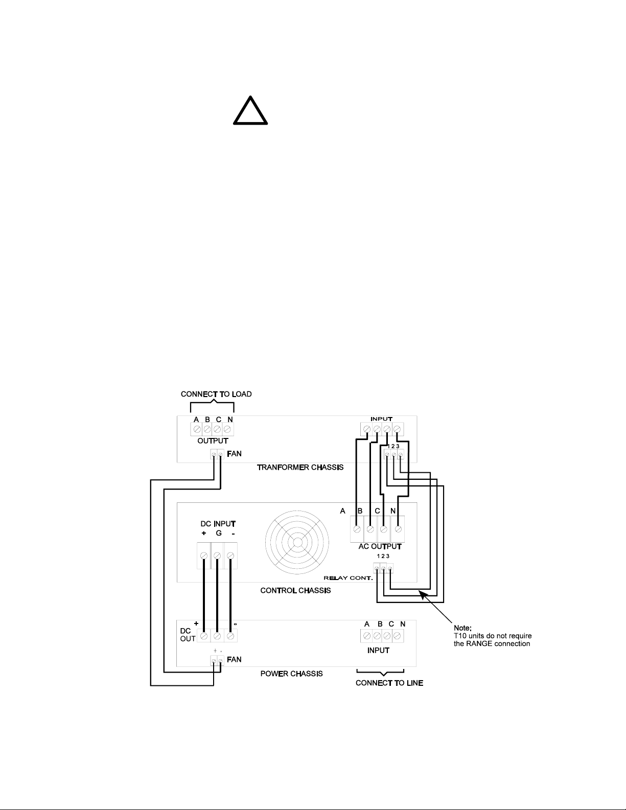
2.4 UNITS WITH T10 OR T10D OPTIONS
The diagram below illustrates chassis inter-connection for units provided with the T10 or T10D options.
The T10D units are dual range versions of the standard T10 type. As shown below this option includes
an additional 7.0 inch high chassis to house the external transformers and range relay for T10 units.
Units supplied with T10 options may vary slightly depending on actual customers requirements. Units
with a or 0 to 300 Vac output are considered standard. Units supplied with other voltages will be
assigned a 4 digit engineering number. T10 units require some special operating considerations. Refer
to section 3 of this manual for operating instructions.
Figure 2-3. T10 / T10D option interconnect

8
2.5 Installation Considerations
This device relies on the proper flow of air to provide internal cooling. Failure to provide this will cause
intermittent shut down of the unit due to overheating and will affect the long term reliability. Air is taken
into to the unit through “grills” in the front and side of the unit. A distance of at least 6 inches must be
maintained between the front intake and any obstruction. Likewise, the heated air is exhausted through
grills in the rear panel. A distance of four inches is required between the rear panel and any obstruction
to prevent “back pressure” from reducing air flow.
This device is intended for use in a relatively clean environment . For this reason, air filters are not
provided on the intakes. If air filtering is desired, it may be added at the expense of reduced air flow.
This may result in some required de-rating of the output power available from this unit.
An additional “stud” has been included on the rear panel of this device. This point may be used for a
protective earth connection to the chassis. This is also a convenient tie point for a “bonding”
conductor or other chassis grounding arrangement. Refer to figure 2-4 below.
Figure 2-4

9
SECTION 3
OPERATION
WARNING
This equipment involves the use of voltages and currents that can be hazardous. Only qualified
personnel should be allowed to operate or service it. The top cover(s) must always be in place
during operation.
3.1 CONTROLS AND INDICATORS
Table 1 lists the controls and indicators used on the different models of the AC Source. The table also includes
their function. Figure 3-1 locates these front panel controls and indicators. Also shown are the rear panel
REMOTE PRGM connector, two terminal strips, cooling fan, and a GND stud.
3.2 TO OPERATE THE EQUIPMENT
1) Ensure that line circuit breaker and OUTPUT switch are set to OFF.
2) Connect suitable load across output terminals. (Do not exceed rating of unit.)
3) Set line circuit breaker of power chassis to ON (cooling fan noise should become evident).
4) Rotate VOLTS control to desired voltage. ( for T10D units, set the range switch as required ).
5) Rotate FREQ control to desired frequency.
6) Set OUTPUT switch to ON to energize load.
NOTE
It is permissible to energize a load gradually by setting the OUTPUT switch
ON and rotating the VOLTS control from zero or a low voltage position up
to the voltage desired.
3.3 SHUTDOWN PROCEDURE
1) Set OUTPUT switch to OFF.
2) Set VOLTS control fully counter- clockwise.
3) Set line circuit breaker to OFF.
3.4 ADJUSTMENT OF LINE DROP COMPENSATION AND PHASE ANGLES
General:
The BL series of power supplies provide a means to compensate for load related effects and a means
to trim the phase angles. A “Line Drop Comp” trim is provided for each phase. Phase trim pots are
provided to adjust the angle from phase A to Phase B ( A-B ) and between phase B and phase C (B-C).
The setting of the line drop comp is done at the factory with a full resistive load. The phase angles are
factory set so the B lags A by 120 electrical degrees and C lags B by 120 electrical degrees. These
adjustments should be periodically confirmed. See the following pages for adjustment procedures.

10
TABLE 3-1. CONTROLS AND INDICATORS
REF CONTROL/INDICATOR FUNCTION
1 Circuit breaker ON: Connects input power to unit.
OFF: Disconnects input power from unit.
2
CONSTANT CURRENT indicator Lights to indicate protective circuits are
automatically operating to provide rated
current and distortion-less output during an
overload condition.
3 “FREQ” control Used to establish output frequency.
4
OUTPUT switch ON: Connects output power to control chassis
rear panel output terminals.
OFF: Disconnects output power at rear panel.
5
OVERLOAD LATCH indicator Lights to indicate short circuit protection for
overload conditions that disables the output.
Overload latch is reset by removing load and
recycling power.
6
OVER-TEMP indicator Lights to indicate over temperature condition
and removal of output power. Output power is
automatically restored on termination of
over-temperature condition.
7
Digital readout meters VOLTS: Provides output voltage (RMS)
display.
AMPS: Provides output current (RMS)
display.
FREQ: Provides output frequency display.
7a Meter Select Switch 3 position rotary that selects which output phase
is displayed on readouts.
8“VOLTS” control Used to establish desired output voltage.
9 Line drop compensation & phase adjust
trim pots.
Allows for output adjustment due to IR drops in
the load lines. One adjustment provided for each
phase. Trim of output phase angles.
10 Output RANGE switch ( optional) Selects output voltage range. Supplied with T5D
option units only.
11 DC Power input Terminal block Connect to +/-250VDC from power section.
Pre-wired on single phase input units. C8 - C10
12 AC output terminal block Connects AC output to user’s load. CAUTION
use top screws only to prevent loss of hardware
inside unit.
13 Remote Connectors (optional) Analog, IEEE-488 , or RS-232 control ports.

11
Figure 3 -1. BL10000 AC Source, Control Chassis Front and Rear Panel Views

12
3.5 ADJUSTMENT OF LINE DROP COMPENSATION
The line drop compensation trim pots on the power source front panel allows the user to compensate
for resistive loses in the load wiring. One trimmer is provided for each of the three output phases. An
external voltmeter with 0.1V resolution is required to properly set this trimmer. Always use a non-
metallic screwdriver for this adjustment.
1.) With the Unit on and stabilized, note the voltage indication on the front panel meter for phase A . Apply
the desired load and use an external voltmeter (as close to the load as practical) to measure the
voltage supplied to the load terminals A and Neutral.
2.) Using an insulated screwdriver, adjust the front panel “LINE DROP COMP” to bring the load terminal
voltage to the same value as that indicated by the front panel voltmeter. This will compensate for I/R
drops due to the load wiring. Note, Line drop comp will not work without a load applied.
3.) Repeat steps 1 and 2 for the remaining phases.
3.6 PHASE ADJUSTMENT
!CAUTION !
MIS-ADJUSTING PHASE ANGLES CAN CAUSE A LARGE IMBALANCE IN CONNECTED LOADS
AS THE LINE TO LINE VOLTAGE ARE AFFECTED. DO NOT ATTEMPT TO ADJUST PHASE WITH
THE LOAD CONNECTED UNLESS THE IMPACT ON THE LOAD IS UNDERSTOOD.
Two front panel trim adjustment are provided for phase angle adjustment. A non-metallic screw
driver is required. To adjust the phase shift between two phases, proceed as follows:
1) Connect an external DVM between NA and NB on the output terminal strip.
2) Turn on circuit breaker and output switch and adjust output to 100 VRMS.
3) To produce a phase shift between phase A and phase B, adjust phase difference between NA - NB until
external DVM indicates the Vrms value required to produce the desired phase angle. Use the table
below as a guide. It shows five predetermined values. For in-between phase angles, use the formulas
shown.
DVM Phase V = [(1-cos N) 20,000]½
(Vrms) Angle(°) N= cos-1 [1-V2/20,000]
81.3 48 where V = Vrms setting on DVM
100.0 60 and N= phase angle desired
141.4 90
173.2 120
190.2 144
4) Connect DVM across NB and NC and repeat and adjust NB - NC trimmer for the desired phase shift
between phases B & C .
IMPORTANT NOTE
The phase shift circuit of this unit are provided allow flexibility. One drawback is that the output must
be set to some value above 10-15 Vrms in order to provide reference signal for these circuits. It must
be noted that the phase angles below this voltage is undefined. This not a problem for most
applications. In the event this causes a problem with the intended application, the phase angle may be
fixed at 120 degrees. Consult the factory for more information.

13
3.7 REMOTE ANALOG CONTROL
REMOTE PRGM CONNECTOR
The REMOTE PRGM connector is a nine-pin female “D” connector located on the rear panel. It provides remote
analog control of the power source’s amplitude, frequency, output relay, and voltage range (TD option only).
A mating nine pin male connector is required for connection. It is recommended the user use multi-conductor
shielded wire to fabricate the control cable. Table 3-2 lists the connector pin descriptions and functions. During
remote operation, the unit's front panel VOLTS and FREQ controls must be set fully counter-clockwise
REMOTE AMPLITUDE AND FREQUENCY CONTROL
Two 0-10 Vdc control voltages from externally isolated voltage sources are used to control the unit's amplitude
and frequency via the fabricated remote cable. Note the control inputs are tied to the power circuit common.
This point is not the same as chassis potential unless externally connected ( see wiring info )
TABLE 3- 2. REMOTE PRGM CONNECTOR PIN DESCRIPTIONS
PIN FUNCTION DESCRIPTION
1 External synch HI The power source will lock to the frequency of the signal
applied to this pin. See external sync below.
2 External synch LO Isolated return for sync signal.
3 DC control common* Common return of power source . CAUTION see note 1
4 Amplitude control (hi) 0-10V applied controls output voltage from 1 - 100%. Input
impedance greater than 50K ohms. 300msec response.
5 Frequency control (hi) 0-10V applied controls output frequency from 45 -500 Hz.
Input impedance greater than 20K ohms.
6 Output relay control Application of short to pins 6-7 will activate the output
relay.
7 Output relay control Application of short to pins 6-7 will activate the output
relay.
8 Range relay control Application of short to pins 8-9 will activate the output
relay.
This function is provided with TD option only .
9 Range relay control Application of short to pins 8-9 will activate the output
relay. This function is provided with TD option only .
*NOTE 1: ISOLATED CONTROL VOLTAGES ARE RECOMMENDED. REMOTE CONTROL
COMMON IS AT THE OUTPUT NEUTRAL POTENTIAL.
3.8 EXTERNAL SYNC
The unit provides for external synchronization via its rear panel REMOTE PRGM connector. When an external
sync signal is applied to the unit, it reacts to produce an output frequency that is equal to the sync signal
regardless of the FREQ control setting. The external sync can be either TTL compatible or an AC signal from
5 to 30 VRMS. Note that a square-wave produces the least amount of phase shift between the sync signal and
output of the power source.
!CAUTION
The external sync signal applied to the unit must not be lower than 45 Hz or higher than 500Hz to
avoid possible damage to the unit.
It is also recommended that load be de-energized and the output voltage of the power supply be set to zero
before connecting a sync signal. This will prevent potentially damaging transients from reaching the load.

14
3.9 OPERATIONAL CONSIDERATIONS
GENERAL
All BL series incorporate an input rectifier system followed by a capacitive filter. To limit the in rush current to
the unit, a soft start circuit is employed. This circuits prevents nuisance tripping of protective circuits in the line
circuits as well as reducing stress on internal components . When the unit is switched off for any reason a period
of about 30 to 60 seconds is required to allow the soft start circuit to “reset” . Failure to do so may cause the front
panel breaker of the power supply to trip repeatedly as power is reapplied. This may lead to eventual failure of
the breaker. In automated systems, a time delay relay should be considered to handle power interruptions.
OPERATION INTO LINEAR LOADS
The BL series will provide the best overall performance into a linear load. A linear load is characterized by that
fact that its current wave shape is sinusoidal. The phase relationship between the voltage and current may be
anything between 0 and 90 degrees (leading or lagging). Some examples of linear loads are as follows:
Most AC Motors Power Transformers Heating Elements
Resistors Capacitors Most Inductors
Incandescent Lighting ( without dimmers ) Most Solenoids
Operation into these types of loads usually cause little interaction with the output stage of the model BL6000.
The main concern with a linear load is the “in-rush” current associated with it. Most heating elements and
resistors have no in-rush concerns and usually do not present any problem for the power source. Inductive and
capacitive loads may present a special problem based on their construction and the way in which they are
energized. Motors and tungsten filament lamps also present some special “start-up” concerns. The following
is intended to give the end user some insight into applying the AC source to these types of loads.
DRIVING REACTIVE LOADS
Capacitors and inductors are reactive in nature. If the load is applied during the peak of the AC cycle there may
be a considerable in-rush of current several magnitudes larger than the steady state current. This current is only
limited by any series resistance that may be present in the load circuit. Under the right conditions, this could trip
the overload protection circuits in the power source. Certain transformers and solenoids (inductance) present
the same problem.
Several methods can be used to prevent tripping the protection circuits in the power source . One common
method is to insert a limiting impedance in series with the load. This could be in the form of a fixed resistor or
NTC (Negative Temperature Coefficient) thermistor. Also, zero crossing switching can be employed. The most
obvious way to prevent a high in-rush current is to apply the load with the voltage set to zero (or some
low value) and energize the load slowly by turning up the voltage.
DRIVING LAMPS
Tungsten filaments lamps, when cold, present a very low resistance. Once they are energized, their resistance
quickly climbs to it’s steady state value. This characteristic must be accounted for when driving tungsten filament
lamps. The same methods for driving reactive loads can be applied to tungsten.
Table of contents
Other BEHLMAN Power Supply manuals

BEHLMAN
BEHLMAN BL20000 Series Use and care manual

BEHLMAN
BEHLMAN PF1352 Series User manual

BEHLMAN
BEHLMAN PF1350 Series Use and care manual

BEHLMAN
BEHLMAN P1350 Use and care manual

BEHLMAN
BEHLMAN BL5000 Series Use and care manual

BEHLMAN
BEHLMAN BL15000 Series Use and care manual

BEHLMAN
BEHLMAN BL3300 Series Use and care manual

BEHLMAN
BEHLMAN P1351 Use and care manual


