DLW500ESA4 WELDER/GENERATOR • OPERATION MANUAL — REV. # 0 (01/13/23) — PAGE 7
SAFETY INFORMATION
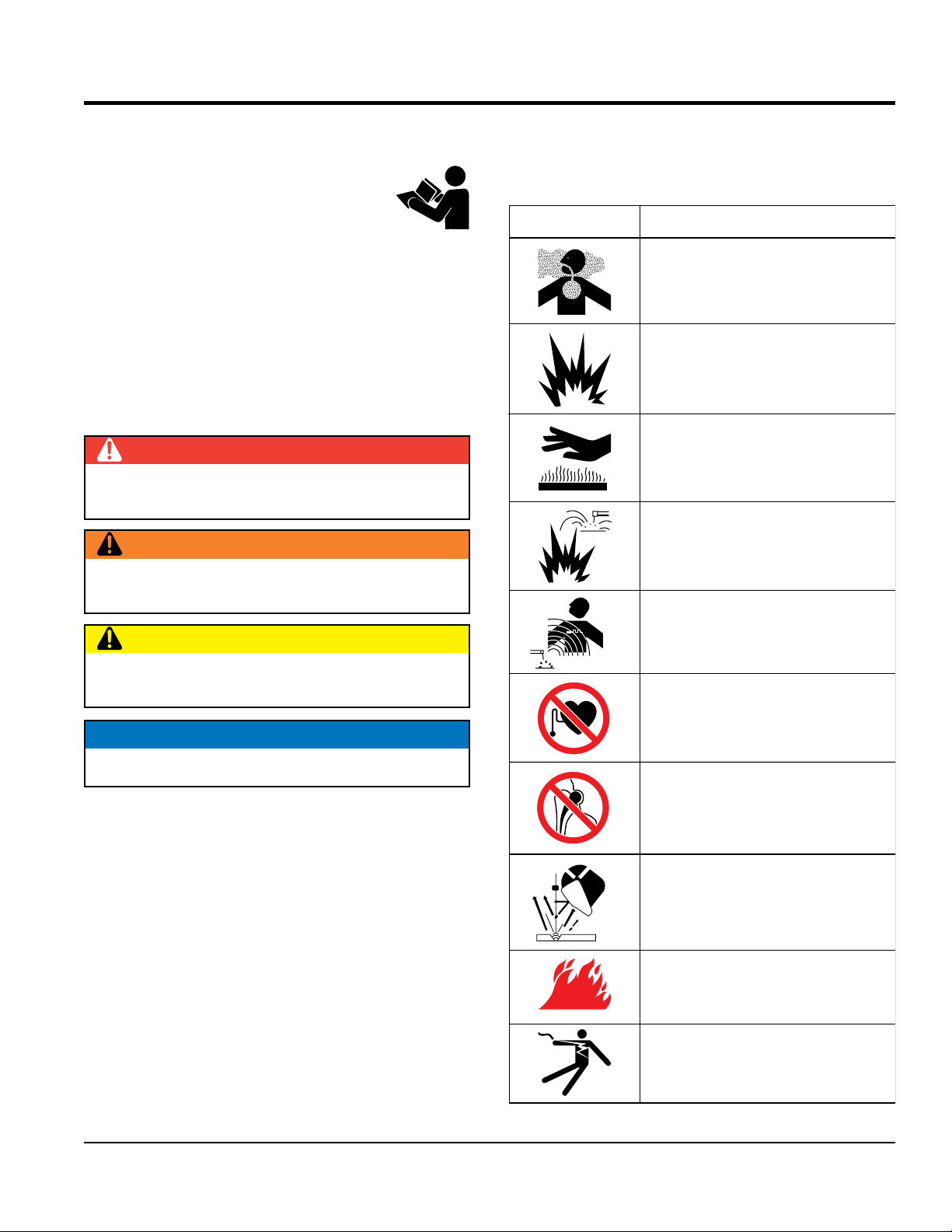
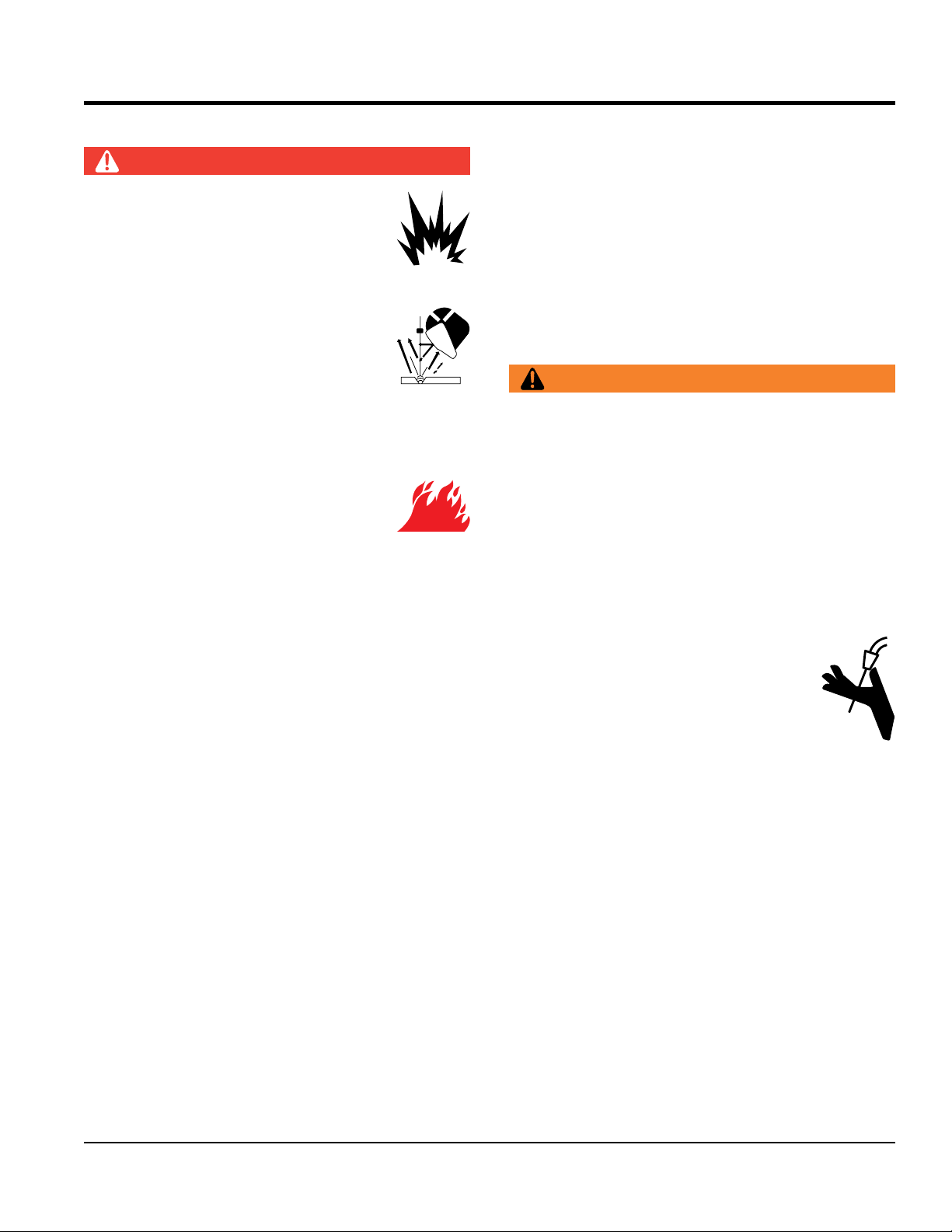
DANGER
NEVER install or operate the welder-
generator in an explosive atmosphere or
near combustible materials. An explosion
or fire could result causing severe bodily
harm or even death.
Flying sparks can cause injury. Wear a face
shield to protect eyes and face.
Remove all flammables within 35 ft (10.7 m)
of welding arc. If this is not possible, tightly
cover them with approved covers.
Do not weld where flying sparks can strike flammable
material.
Hot metal from air arc cutting and gouging
can cause fire or explosion. DO NOT cut or
gouge near flammables.
Welding on closed containers, like tanks, drums or
pipes, can cause them to blow up. DO NOT weld on
closed containers unless they are properly prepared
according to AWS F4.1 (see Recommended Safe
Practices for the Preparation for Welding and Cutting of
Containers and Piping from American Welding Society
Standards). Check and be sure area is safe before doing
any welding.
Protect yourself and others from flying sparks and hot metal.
Wear oil-free protective garments like leather gloves,
heavy shirt, cuffless trousers, high shoes and a cap.
Be alert that welding sparks and hot materials from
welding can go through small cracks and openings to
adjacent areas.
Be aware that welding on a ceiling, floor, bulkhead or
partition can cause fire on hidden side.
Connect welding cable to the work as close to welding
area as practical to prevent welding current from traveling
long, possibly unknown paths and causing electric shock,
sparks and fire hazards.
DO NOT use welder-generator to thaw frozen pipes.
Remove stick electrode from holder or cut off welding
wire at contact tip when not in use.
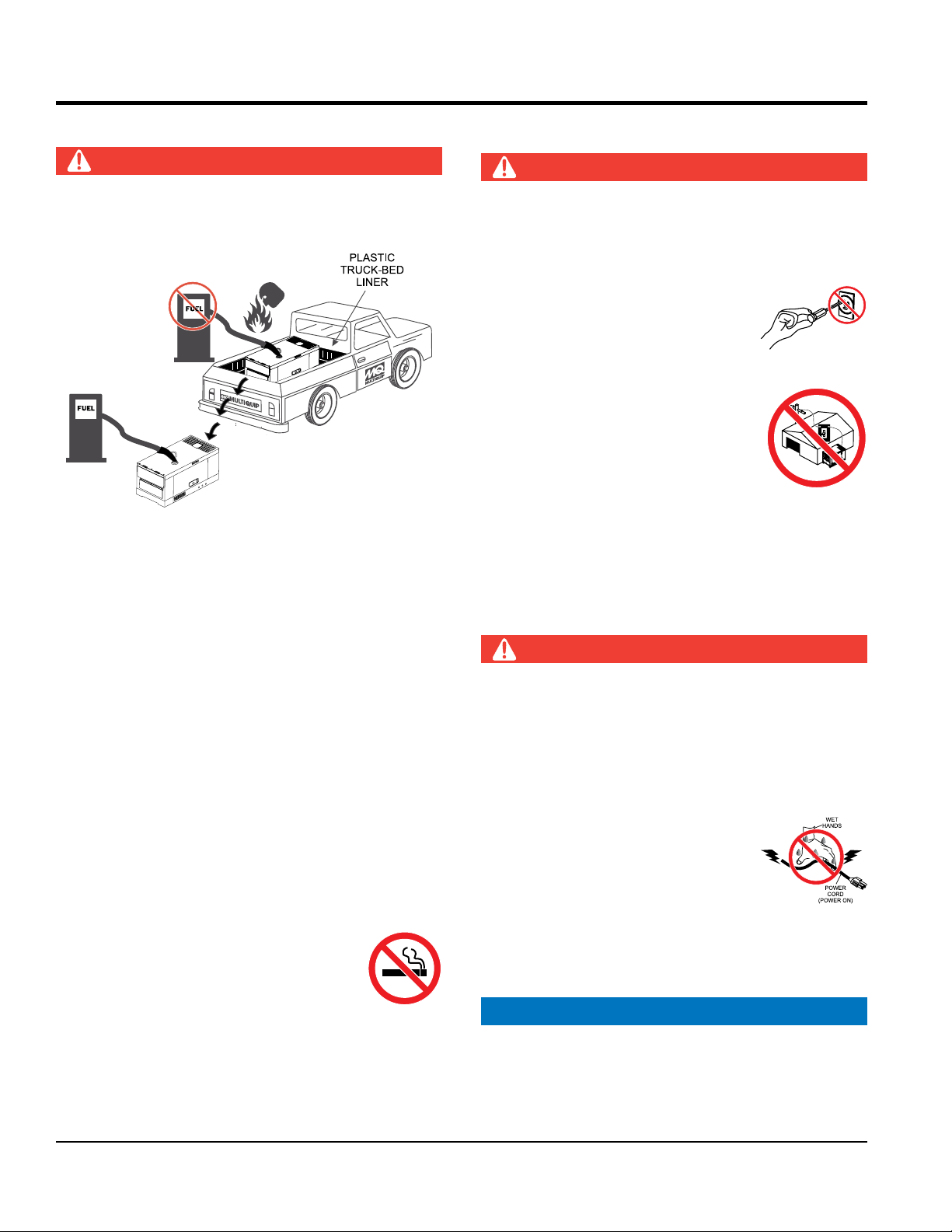
DO NOT touch output terminals during operation.
Contact with output terminals during operation can cause
electrocution, electrical shock or burn.
Remove any combustibles, such as a butane lighter or
matches, from your person before doing any welding.
After completion of work, inspect area to ensure it is free
of sparks, glowing embers and flames.
Follow requirements in OSHA 1910.252 (a) (2) (iv) and
NFPA 51B for hot work and have a fire watcher and
extinguisher nearby.
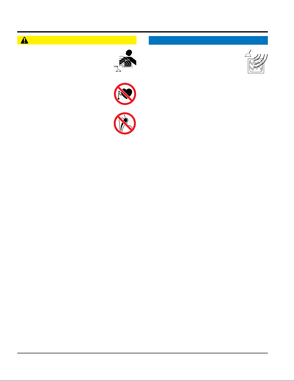
WARNING
Keep your head out of the fumes. Use enough ventilation
or exhaust at the arc, or both, to keep the fumes and
gases from your breathing zone and the general area.
In a large room or outdoors, natural ventilation may be
adequate if you keep your head out of the fumes.
DO NOT
get too close to the arc. Use corrective lenses
if necessary to stay a reasonable distance away from
the arc.
Use natural drafts or fans to keep the fumes away from
your face.
Welding wire can cause injury. Do not press
gun trigger until instructed to do so. Do
not point gun toward any part of the body,
other people or any metal when threading
welding wire.
Have only qualified people remove doors, panels,
covers or guards for maintenance and troubleshooting
if necessary.
Reinstall doors, panels, covers or guards when servicing
is finished and before starting engine.
NEVER disconnect any
emergency or safety devices.
These devices are intended for operator safety.
Disconnection of these devices can cause severe injury,
bodily harm or even death. Disconnection of any of these
devices will void all warranties.