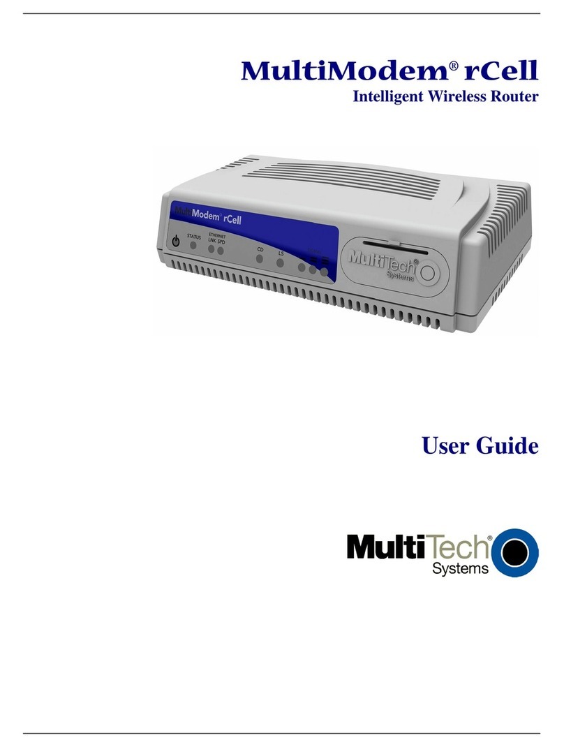
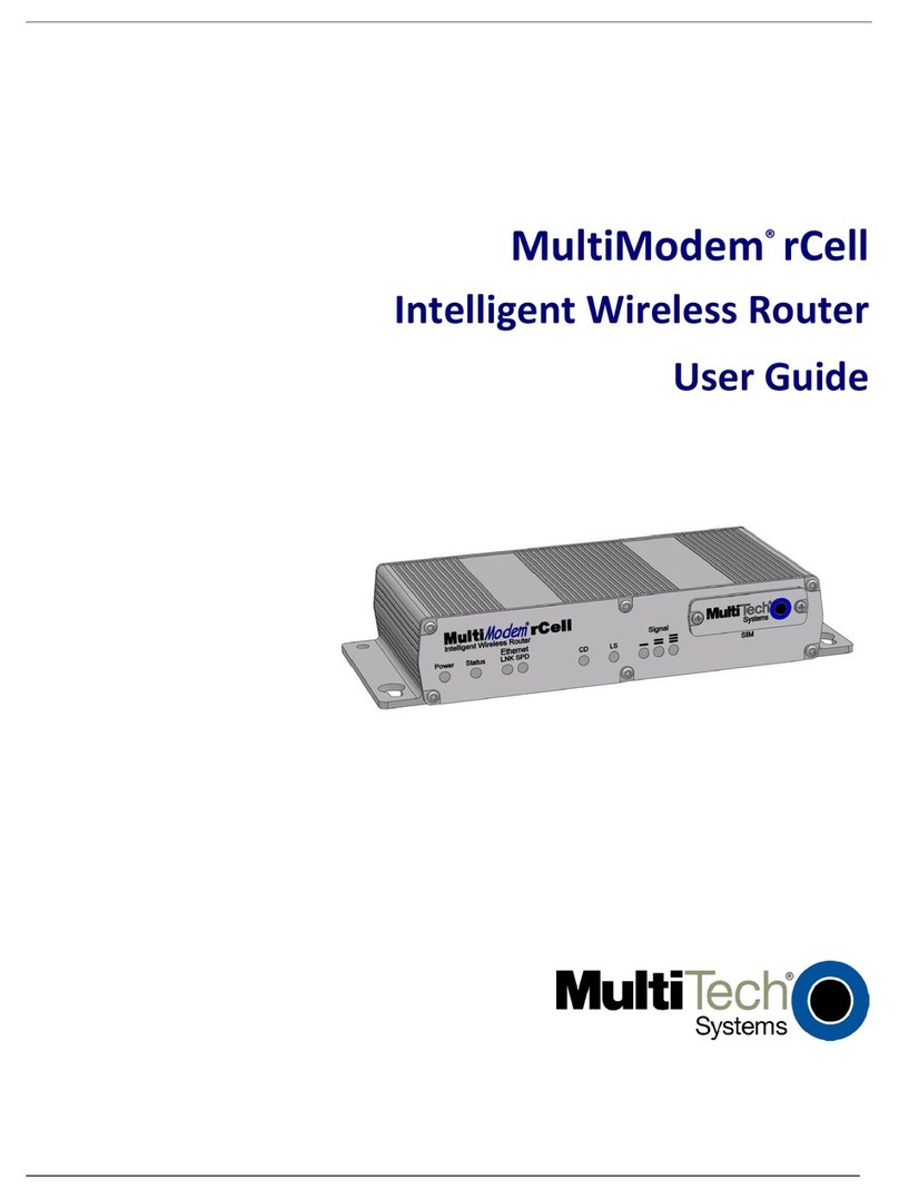
Multitech MultiModem rCell User manual

MultiModem®rCell
Intelligent Wireless Router
User Guide

Copyright and Technical Support
2Multi-Tech Systems, Inc. MultiModem rCell User Guide
MultiModem® rCell User Guide
Intelligent Wireless Router
MTCBA-Xx-EN2 , MTCBA-Xx-EN2-GP
S000485B, Revision B
Copyright
This publication may not be reproduced, in whole or in part, without prior expressed written permission from Multi-Tech
Systems, Inc. All rights reserved.
Copyright © 2010 by Multi-Tech Systems, Inc.
Multi-Tech Systems, Inc. makes no representation or warranties with respect to the contents hereof and specifically disclaims
any implied warranties of merchantability or fitness for any particular purpose.
Furthermore, Multi-Tech Systems, Inc. reserves the right to revise this publication and to make changes from time to time in the
content hereof without obligation of Multi-Tech Systems, Inc., to notify any person or organization of such revisions or changes.
Check Multi-Tech’s Web site or product CD for current versions of our product documentation.
Record of Revisions
74B98BRevision Date Description
A08/31/10 Initial release of MultiModem rCell with GPS and without GPS for C1,E1,G2,H4,
and EV2 models.
B 10/25/10 Added Sprint and Verizon Activation into a new Carrier Activation chapter
(Chapter 3) and restructure installation.
75B99BTrademarks
Trademarks and registered trademarks of Multi-Tech Systems, Inc. include MultiModem, the Multi-Tech logo, and Multi-Tech.
Windows is a registered trademark of Microsoft Corporation in the United States and other countries. All other products or
technologies referenced in this manual are the trademarks or registered trademarks of their respective holders.
Contacting Multi-Tech Support
Online Support Portal: https://support.multitech.com
In order to better serve our customers, manage support requests and shorten resolution times, we have created the online web
portal allowing you to submit questions regarding Multi-Tech products directly to our technical support team. Get answers to
your most complex questions, ranging from implementation, troubleshooting, product configuration, firmware upgrades and
much more.
To create an account and submit a Support Case on the Portal, visit https://support.multitech.com.
Knowledge Base and Support Services: www.multitech.com/support.go
The Knowledge Base provides immediate answers to your questions and gives you access to support resolutions for all Multi-
Tech products. Visit our support area on the website for other support services.
World Headquarters
Multi-Tech Systems, Inc.
2205 Woodale Drive, Mounds View, Minnesota 55112 U.S.A.
Phone: 763-785-3500 or 800-328-9717 Fax: 763-785-9874
www.multitech.com
Technical Support
Business Hours: M-F, 9am to 5pm CST
Country By Email By Phone
Europe, Middle East, Africa: support@multitech.co.uk (44) 118 959 7774
U.S., Canada, all others: support@multitech.com (800) 972-2439 or (763) 717-5863
Warranty
Warranty information can be found at: http://www.multitech.com/warranty.go

Table of Contents
Multi-Tech Systems, Inc. MultiModem rCell User Guide 3
Table of Contents
CHAPTER 1 – INTRODUCTION AND PRODUCT DESCRIPTION ....................................5
Related Documentation........................................................................................................................................ 6
MultiModem MTCBA-E1-EN2 (EDGE)........................................................................................................... 6
MultiModem MTCBA-G2-EN2 (GPRS) .......................................................................................................... 6
MultiModem MTCBA-C1-EN2 (CDMA) .......................................................................................................... 6
MultiModem MTCBA-H4-EN2 (HSPA)........................................................................................................... 6
MultiModem MTCBA-EV2-EN2 (EV-DO)....................................................................................................... 6
Safety Warnings ................................................................................................................................................... 7
Ethernet Ports Caution .................................................................................................................................... 7
12B12BHandling Precautions ...................................................................................................................................... 7
RF Interference Issues.................................................................................................................................... 7
Vehicle Safety.................................................................................................................................................. 7
14B14BInternal Lithium Battery.................................................................................................................................... 7
Front Panel ........................................................................................................................................................... 8
Package Contents ................................................................................................................................................ 9
Specifications...................................................................................................................................................... 10
Power............................................................................................................................................................. 11
RF Specifications........................................................................................................................................... 11
Global Positioning System (GPS)....................................................................................................................... 12
RS232 9-Pin Functions of the Female End Connector ...................................................................................... 12
CHAPTER 2 – INSTALLATION .................................................................................................... 13
Insert the SIM Card into Holder, If required........................................................................................................ 13
Making the Connection....................................................................................................................................... 13
Optional – Attach the Router to a Flat Surface................................................................................................... 15
24B24BSet Your PC’s TCP/IP Address for Ethernet Functionality................................................................................. 16
Configure Ethernet Interface Using Web Management Software ...................................................................... 18
CHAPTER 3 – CARRIER ACTIVATION ..................................................................................... 21
Account Activation for Wireless Devices ............................................................................................................ 21
Verifying Signal Strength.................................................................................................................................... 21
Checking Network Registration and Roaming Status ........................................................................................ 21
Verizon Wireless Networks Activation................................................................................................................ 22
Sprint Network Activation.................................................................................................................................... 22
GSM Network Activation..................................................................................................................................... 22
Exiting Modem Mode.......................................................................................................................................... 22
CHAPTER – 4 USING THE WEB MANAGEMENT SOFTWARE......................................23
29B29BNavigating the Web Management Software....................................................................................................... 23
Web Management Software Screens................................................................................................................. 25
IP Setup.............................................................................................................................................................. 25
IP Setup > GPS Configuration............................................................................................................................ 31
PPP..................................................................................................................................................................... 33
Networks & Services........................................................................................................................................... 40
GRE Tunnels ...................................................................................................................................................... 46
DHCP Server...................................................................................................................................................... 48
IPSec .................................................................................................................................................................. 50
37B38Serial-Port........................................................................................................................................................... 55
38BSerial-Port > Serial Port Settings........................................................................................................................ 55
Tools................................................................................................................................................................... 58
69BTools > Tools................................................................................................................................................. 58
70BTools > Firmware Upgrade............................................................................................................................ 58
71BTools > Load Configuration........................................................................................................................... 59
51BTools > Save Configuration........................................................................................................................... 59
40B40BStatistics & Logs ................................................................................................................................................. 60
52B80BStatistics & Logs > System Information......................................................................................................... 60
53B81BStatistics & Logs > Ethernet.......................................................................................................................... 61
54B82BStatistics & Logs > PPP................................................................................................................................. 62
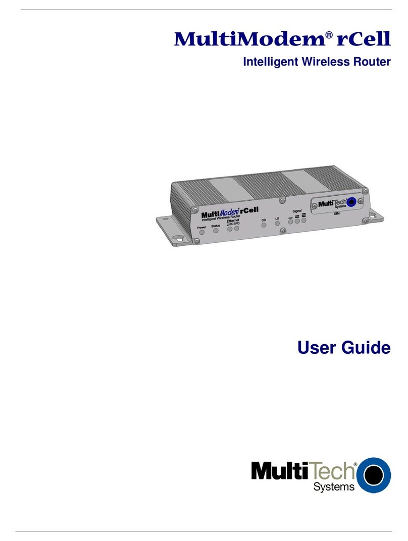
Table of Contents
4Multi-Tech Systems, Inc. MultiModem rCell User Guide
55B83BStatistics & Logs > PPP Trace ...................................................................................................................... 63
57B86BStatistics & Logs > Modem Information......................................................................................................... 64
58B87BStatistics & Logs > Service Status................................................................................................................. 64
59B88BStatistics & Logs > TCP/UDP Client Live Log............................................................................................... 64
60B89BStatistics & Logs > TCP/UDP Server Live Log.............................................................................................. 64
61B90BStatistics & Logs > IPSec Live Log................................................................................................................ 65
62B91BStatistics & Logs > IPSec Log Traces........................................................................................................... 65
3BAPPENDIX A – COMMONLY SUPPORTED SUBNETS REFERENCE TABLE ........... 66
AAPPENDIX B - CELLULAR INFORMATION........................................................................... 68
Antenna System for Cellular Devices................................................................................................................. 68
FCC Requirements for the Antenna ................................................................................................................... 68
Antenna Specifications ....................................................................................................................................... 68
CDMA RF Specifications............................................................................................................................... 68
PTCRB Requirements for the Antenna......................................................................................................... 68
GSM/EGSM RF Specifications...................................................................................................................... 68
GSM Antenna Requirements/Specifications................................................................................................. 69
GPS (Global Positioning) RF Specifications ................................................................................................. 69
Antennas Available from Multi-Tech Systems, Inc........................................................................................ 70
5BAPPENDIX C – REGULATORY COMPLIANCE ...................................................................... 71
EMC, Safety, and R&TTE Directive Compliance................................................................................................ 71
FCC Part 15 Class A Statement......................................................................................................................... 71
Industry Canada ................................................................................................................................................. 71
6BAPPENDIX D – WASTE ELECTRICAL AND ELECTRONIC EQUIPMENT...................72
7BAPPENDIX E – ENVIRONMENTAL INFORMATION ...........................................................73
Restriction of the Use of Hazardous Substances (RoHS).................................................................................. 73
China ROHS....................................................................................................................................................... 74
REACH Statement.............................................................................................................................................. 75
APPENDIX F – SPRINT ACTIVATION FAILURE CORRECTIVE ACTION ................. 76
INDEX.................................................................................................................................................... 78

Multi-Tech Systems, Inc. MultiModem rCell User Guide 5
Chapter 1 – Introduction and Product
Description
This User Guide describes the MultiModem® rCell intelligent wireless routers with an Ethernet II interface. The MultiModem
rCell Router is configured for one of three connectivity modes: always-on, wake-up on ring, or dial-on demand. The always-on
network connection automatically establishes a wireless data connection and allows for around the clock surveillance,
monitoring or real time data acquisition of any remote Ethernet device such as a Web camera. If the data link is dropped in the
event of poor reception or a complete loss of service, it will automatically re-establish the data link. The wake-up on ring
configuration allows the router to “wake up” and initiate a connection when it detects an incoming ring. For security reasons, you
can setup the router to wake up based on a particular caller ID number. This configuration is ideal for reducing the costs
associated with the modem being online and available 24/7. When configured for dial-on demand, the router only accesses the
Internet when data is present. This configuration is ideal for sharing Internet access among networked PCs.
Model Description
MTCBA-E1-EN2 Quad-band E-GPRS Class 12 performance Without GPS Option
MTCBA-E1-EN2-GP Quad-band E-GPRS Class 12 performance With GPS Option
MTCBA-G2-EN2 Quad-band GPRS Class 10 performance Without GPS Option
MTCBA-G2-EN2-GP Quad-band GPRS Class 10 performance With GPS Option
MTCBA-C1-EN2 Multi-band CDMA2000 1xRTT performance Without GPS Option
MTCBA-C1-EN2-GP Multi-band CDMA2000 1xRTT performance With GPS Option
MTCBA-H4-EN2
Tri-band UMTS/HSPA 7.2 performance Without GPS Option
MTCBA-H4-EN2-GP
Tri-band UMTS/HSPA 7.2 performance With GPS Option
MTCBA-EV2-EN2 Dual-band 800/1900 MHz EV-DO Rev A performance Without GPS Option
MTCBA-EV2-EN2-GP
Dual-band 800/1900 MHz EV-DO Rev A performance With GPS Option

Chapter 1 – Product Description and Specifications
6Multi-Tech Systems, Inc. MultiModem rCell User Guide
Related Documentation
MultiModem MTCBA-E1-EN2 (EDGE)
AT Commands: The MultiModem MTCBA-E1-EN2 wireless router is configured using the EDGE AT
Commands. These commands are documented in the Reference Guide for the MultiModem Wireless EDGE
Modems, document number S000474x.
MultiModem MTCBA-G2-EN2 (GPRS)
AT Commands: The MultiModem MTCBA-G2-EN2 wireless modem is configured using the GPRS
AT Commands. These commands are documented in the Reference Guide for the MultiModem
Wireless GPRS Modems, document number S000463x.
MultiModem MTCBA-C1-EN2 (CDMA)
AT Commands: The MultiModem MTCBA-C1-EN2 wireless router is configured using the CDMA-C1 AT
Commands. These commands are documented in the Reference Guide for the MultiModem Wireless
CDMA-C1 Modems, document number S000478x.
MultiModem MTCBA-H4-EN2 (HSPA)
AT Commands: The MultiModem MTCBA-H4-EN2 wireless router is configured using the HSPA AT
Commands. These commands are documented in the Reference Guide number S000483x.
MultiModem MTCBA-EV2-EN2 (EV-DO)
AT Commands: The MultiModem MTCBA-EV2-EN2 wireless router is configured using the EV-DO
AT Commands. These commands are documented in the Reference Guide number S000482x.

Chapter 1 – Product Description and Specifications
Multi-Tech Systems, Inc. MultiModem rCell User Guide 7
Safety Warnings
Ethernet Ports Caution
The Ethernet ports are not designed to be connected to a Public Telecommunication Network or used outside the building.
12B12BHandling Precautions
All devices must be handled with certain precautions to avoid damage due to the accumulation of static charge. Although
input protection circuitry has been incorporated into the devices to minimize the effect of this static build up, proper
precautions should be taken to avoid exposure to electrostatic discharge during handling and mounting.
Caution: Maintain a separation distance of at least 20 cm (8 inches) between the transmitter’s antenna and the body of the
user or nearby persons. The router is not designed for, nor intended to be, used in applications within 20 cm (8 inches) of the
body of the user.
RF Interference Issues
It is important to follow any special regulations regarding the use of radio equipment due in particular to the possibility of radio
frequency, RF, interference. Please follow the safety advice given below carefully.
●Switch OFF your Wireless MultiModem when in an aircraft. The use of cellular telephones in an aircraft may
endanger the operation of the aircraft, disrupt the cellular network and is illegal. Failure to observe this instruction
may lead to suspension or denial of cellular telephone services to the offender, or legal action or both.
●Switch OFF your Wireless MultiModem when around gasoline or diesel-fuel pumps and before filling your vehicle
with fuel.
●Switch OFF your Wireless MultiModem in hospitals and any other place where medical equipment may be in use.
●Respect restrictions on the use of radio equipment in fuel depots, chemical plants or where blasting operations are in
progress.
●There may be a hazard associated with the operation of your Wireless MultiModem close to inadequately protected
personal medical devices such as hearing aids and pacemakers. Consult the manufacturers of the medical device to
determine if it is adequately protected.
●Operation of your Wireless MultiModem close to other electronic equipment may also cause interference if the
equipment is inadequately protected. Observe any warning signs and manufacturers’ recommendations.
Vehicle Safety
●Do not use your Router while driving, unless equipped with a correctly installed vehicle kit allowing ‘Hands-Free’
Operation.
●Respect national regulations on the use of cellular telephones in vehicles. Road safety always comes first.
●If incorrectly installed in a vehicle, the operation of router telephone could interfere with the correct functioning of
vehicle electronics. To avoid such problems, be sure that qualified personnel have performed the installation.
Verification of the protection of vehicle electronics should be part of the installation.
●The use of an alert device to operate a vehicle’s lights or horn on public roads is not permitted.
14B14BInternal Lithium Battery
●A lithium battery located within product provides backup power for the timekeeping capability. The battery has an
estimated life expectancy of ten years.
●When the battery starts to weaken, the date and time may be incorrect. If the battery fails, the board must be sent
back to Multi-Tech Systems for battery replacement.
●Lithium cells and batteries are subject to the Provisions for International Transportation. Multi-Tech Systems Inc.
confirms that the Lithium batteries used in the Multi-Tech product(s) referenced in this manual comply with Special
Provision 188 of the UN Model Regulations, Special Provision A45 of the ICAO-TI/IATA-DGR (Air), Special
Provision 310 of the IMDG Code, and Special Provision 188 of the ADR and RID (Road and Rail Europe).
Warning! There is danger of explosion if the battery is incorrectly replaced!

Chapter 1 – Product Description and Specifications
8Multi-Tech Systems, Inc. MultiModem rCell User Guide
Front Panel
The front panel contains Power and Status LEDs, two Ethernet LEDs, two modem LEDs, and three signal LEDs. The Power
LED indicates that DC power is present and the Status LED blinks when the unit is functioning normally. The two Ethernet LEDs
indicate transmit and receive activity and connection speed of 10 or 100Mbps on the Ethernet link. The two modem LEDs
indicate carrier detection and link status. The three signal LEDs display the signal strength level of the wireless connection. The
SIM door on the right side of the router provides access to the SIM card holder on the E1, G2, and H4 versions.
Model MTCBA-E1/G2/H4-EN2
Model MTCBA-C1/EV2-EN2
LED Indicators
Power
Indicates presence of DC power when lit.
Status The LED is a solid light when the rCell is booting up, saving the configuration, restarting, or updating the firmware.
When the Status LED begins to blink, the router is ready.
LNK Link. Blinks when there is transmit and receive activity on the Ethernet link. It shows a steady light when there is a
valid Ethernet connection.
SPD
Speed. Lit when the Ethernet is linked at 100 Mbps. If it is not lit, the Ethernet is linked at 10 Mbps.
CD
Carrier Detect. Lit when data connection has been established.
LS
Link Status Dependent on Model
-E1 version* (AT^SSYNC=1)
G2 version
C1version
-H4 and EV2 versions
Permanently off. ME is in one of
the following modes: Power Down
mode, Airplane mode Non-Cyclic
Sleep mode with no temporary
wake-up event in progress.
600 ms on/600 ms off
Limited Network Service: No SIM
card inserted or no PIN entered, or
network search in progress or
ongoing user authentication, or
network login in progress.
75 ms on/3 sec off
Idle mode: The mobile is registered
to the GSM network (monitoring
control channels and user
interactions). No call is in progress.
75 ms on/ 75 ms off/75 ms on/3
sec off
One or more GPRS contexts
activated.
500 ms on/ 25 ms off
Packet switched data transfer in
progress.
Permanently on
CSD call – Connected to remote
party.
Permanently On: Not
registered on network.
Flashing states:
200 ms on/2 sec off
Registered on network.
200 ms on/600 ms off
Registered on the
network and
communications in
progress
100 ms on/200 ms off
Software downloaded
is either corrupted or
non-compatible (“bad
software”)
Permanently On:
Not registered on
network.
Flashing states:
200 ms on/2 sec off
Registered on
network.
200 ms on/600 ms
off
Registered on the
network and
communications in
progress
100 ms on/200 ms
off
Software downloaded
is either corrupted or
non-compatible (“bad
software”)
Permanently On:
Powered on and
connected, but not
transmitting or receiving.
Slow flashing state
(5 Seconds)
Powered on searching
for a connection.
Fast flashing state
(0.3 seconds)
Transmitting and
receiving.
Signal ALL OFF - Unit is off, not registered on network, or extremely week signal (0 < = RSSI < 6).
1 Bar “ON” – Very weak signal (7 < = RSSI <14)
1 Bar and 2 Bar “ON” – Weak signal (15 < = RSSI <23)
1 Bar, 2 Bar, and 3 Bar “ON” – Good signal (24 <= RSSI > = 31)
* To be accurate, the AT^SSYNC command must be set to 1 so that the factory default LED timings are used.

Chapter 1 – Product Description and Specifications
Multi-Tech Systems, Inc. MultiModem rCell User Guide 9
Package Contents
Unbundled Package with
No Accessories
Bundled Package
with Accessories
1 router
1 Quick Start Guide
1 MultiModem CD
Note: You must supply mounting screws,
AC or DC power supply, and an antenna.
1 router
1 antenna
1 Ethernet cable
1 RS-232 cable
1 power supply
1 Quick Start Guide
1 MultiModem CD
Note: You must supply mounting screws.
Note: Your wireless provider will supply the SIM card.

Chapter 1 – Product Description and Specifications
10 Multi-Tech Systems, Inc. MultiModem rCell User Guide
Specifications
Features
MTCBA-E1-EN2
MTCBA-C1-EN2
MTCBA-G2-EN2 MTCBA-H4-EN2
MTCBA-EV2-EN2
Performance EDGE: E-GPRS Class 12,
GPRS:
Class 10 CDMA2000 1xRTT GPRS Class 10 HSPA CDMA2000 1xRTT
EV-DO Rev. A
Band, Frequency Quad-band GSM/GPRS/EDGE
850/900/1800/1900 MHz Dual-band 800/1900 MHz CDMA;
800 MHz and 800/1900 MHz with
R-UIM support
Quad-band GSM
850/900/1800/1900 MHz HSUPA / HSDPA / UMTS Triple-
band: 2100/1900/850 MHz with Rx
diversity
Dual-band 800/1900 MHz CDMA;
800 MHz and 800/1900 MHz with
R-UIM support
Packet Data EDGE: E-GPRS Up to 240K bps,
coding scheme MCS1-9, mobile
station Class B, LLC layer, 4 time
slots
GPRS: Full PBCCH support,
coding scheme 1-4, mobile station
Class B
Up to 153.6K bps forward and
reverse Up to 85.6K bps, coding schemes
CS1 to CS4 HSDPA data service of up to
7.2 Mbps
HSUPA data service of up to
5.76 Mbps
Peak download 3.1 Mbps, peak
upload 1.8 Mbps
Circuit-Switched
Data
Up to 14.4K bps, non-transparent IS-95A, IS-95B up to 14.4K bps
forward and reverse Up to 14.4K bps transparent and
non-transparent Up to 14.4K bps transparent and
non-transparent IS-95A, IS-95B up to 14.4K bps
forward and reverse
Short Message
Services-SMS
Text & PDU, Point-to-Point
(MO/MT), cell broadcast Text & PDU, Point-to-Point
(MO/MT), cell broadcast Text & PDU, Point-to-Point, cell
broadcast Text & PDU, Point-to-Point
(MO/MT), cell broadcast Text & PDU, Point-to-Point
(MO/MT), cell broadcast
Antenna
Connector
RF Antenna: 50 ohm SMA (female
connector)
RF Antenna: 50 ohm SMA (female
connector)
RF Antenna: 50 ohm SMA
(female connector)
RF Antenna: 50 ohm SMA (female
connector)
RF Antenna: 50 ohm SMA (female
connector)
SIM Connector Standard 1.8 and 3V SIM
receptacle
- Standard 1.8 and 3V SIM
receptacle
Standard 1.8 and 3V SIM
receptacle
-
RS232 Connector
DE9
Power Connector
2.5mm miniature (screw-on)
Voltage
9V to 32 VDC
Physical
Description
7”W x 1.24”H x 2.93”D 0.75lbs 17.78cmW x3.15cmH x7.44cmD 0.340Kg
Operating
Temperature *
-35° to +75° C*-40° to +85° C* -40° to +85° C* -30° to +60° C* -40° to +75° C*
Storage Temp
-40° to +85° C
Humidity
Relative humidity 20% to 90% noncondensing
Certifications
EMC Compliance
FCC Part 15
EN55022
EN55024
Radio Compliance
FCC Part 22, 24
RSS132,133
EN301 489-1
EN489-3 (-GP only)
EN301 489-7
EN301 511
AS/ACIF S042.1, S042.3
Safety: UL60950-1
cUL60950-1
IEC60950-1
Network: PTCRB
EMC Compliance
FCC Part 15
Radio Compliance
FCC Part 22, 24
RSS132,133
Safety: UL60950-1
cUL60950-1
IEC60950-1
Network: CDG 1&2
EMC Compliance
FCC Part 15
EN55022
EN55024
Radio Compliance
FCC Part 22, 24
RSS132,133
EN301 489-1
EN489-3 (-GP only)
EN301 489-7
EN301 511
AS/ACIF S042.1, S042.3
Safety: UL60950-1
cUL60950-1
IEC60950-1
AS/NZS60950-1
Network:
PTCRB
EMC Compliance
FCC Part 15
EN55022
EN55024
Radio Compliance
FCC Part 22, 24
RSS132,133
EN301 489-1
EN489-3 (-GP only)
EN301 489-7
EN301 511
AS/ACIF S042.1, S042.3
Safety: UL60950-1
cUL60950-1
IEC60950-1
Network: PTCRB
EMC Compliance
FCC Part 15
Radio Compliance
FCC Part 22, 24
RSS132,133
Safety: UL60950-1
cUL60950-1
IEC60950-1
Network: CDG 1&2
* UL Listed @ 40° C, limited by power supply. UL Certification does not apply or extend to an ambient above 40° C and has not been evaluated by UL for ambient greater than 40° C.
“UL has evaluated this device for use in ordinary locations only. Installation in a vehicle or other outdoor locations has not been evaluated by UL. UL Certification does not apply or extend to use
in vehicles or outdoor applications or in ambient above 40° C.”

Chapter 1 – Product Description and Specifications
Multi-Tech Systems, Inc. MultiModem rCell User Guide 11
Power
MTCBA-E1-EN2 MTCBA-C1-EN2 MTCBA-G2-EN2 MTCBA-H4-EN2 MTCBA-EV2-EN2
Sleep:0.175A,1.6W@9V,
0.090A,1.8W@ 20V,
0.060A,1.9W @ 32V
Typical: 0.277A, 2.5W@9V,
0.133A, 2.7W@ 20V,
0.089A, 2.8W @ 32V
Max: 0.506A, 4.5W @ 9V,
0.240A, 4.8W @ 20V,
0.150A, 4.8W @ 32V
Peak: 2.50A @ 9V, 1.00A @ 20V,
0.60A @ 32V
Sleep: 0.186A,1.7W @ 9V,
0.091A,1.8W @ 20V,
0.061A, 2.0W @ 32V
Typical: 0.283A, 2.6W @ 9V,
0.137A, 2.7W @ 20V,
0.088A, 2.8W @ 32V
Max: 0.457A, 4.1W, @ 9V,
0.214A, 4.3W, @ 20V,
0.138A, 4.4W @ 32V
Sleep:0.163A,1.5W @ 9V,
0.082A,1.6W @ 20V,
0.055A,1.8W @ 32V
Typical: 0.240A, 2.2W @ 9V,
0.114A, 2.3W @ 20V,
0.077A, 2.5W @ 32V
Max: 0.340A, 3.0W @ 9V,
0.153A, 3.1W @ 20V,
0.100A, 3.2W @ 32V
Peak: 1.300A @ 9V,0.518A @
20V, 0.343A @ 32V
GSM 850
Sleep 0.205A, 1.89W @9v, 0.110A,
2.20W @20v, 0.068A, 2.18W @32v
Typical 0.240A, 2.21W @9v, 0.114A,
2.28W @20v, 0.077A, 2.46W @32v
Max 0.429A, 3.91W @9v, 0.153A,
3.06W @20v, 0.100A, 3.20W @32v
Peak 2.50A @9v, 0.812A @20v,
0.500A @32v
HSPA
Sleep 0.205A, 1.89W @9v, 0.110A,
2.20W @20v, 0.068A, 2.18W @32v
Typical 0.480A, 4.38W @9v, 0.230A,
4.60W @20v, 0.148A, 4.74W @32v
Max 0.640A, 5.79W @9v, 0.290A,
5.80W @20v, 0.190A, 6.08W @32v
CDMA2000
Sleep 0.125A, 1.15W @9v, 0.060A,
1.20W @20v, 0.044A, 1.41W @32v
Typical 0.215A, 1.98W @9v, 0.130A,
2.60W @20v, 0.085A, 2.72W @32v
Max 0.600A, 5.45W @9v, 0.297A,
5.94W @20v, 0.195A, 6.05W @32v
EV-DO
Sleep 0.125A, 1.15W @9v, 0.060A,
1.20W @20v, 0.044A, 1.41W @32v
Typical 0.335A, 3.08W @9v, 0.190A,
3.30W @20v, 0.125A, 4.00W @32v
Max 0.672A, 6.10W @9v, 0.320A,
6.40W @20v, 0.204A, 6.53W @32v
MTCBA-E1-EN2-GP
MTCBA-C1-EN2-GP
MTCBA-G2-EN2-GP
MTCBA-H4-EN2-GP
MTCBA-EV2-EN2-GP
Sleep:0.188A,1.7W @ 9V,
0.095A,1.9W @ 20V,
0.061A,1.9W @ 32V
Typical: 0.297A, 2.7W @ 9V,
0.138A, 2.8W @ 20V,
0.092A, 2.9W @ 32V
Max: 0.513A, 4.5W @ 9V,
0.240A, 4.8W @ 20V,
0.152A, 4.8W @ 32V
Peak:
2.50A@ 9V, 1.000A@ 20V,
0.625A@ 32V
Sleep: 0.186A,1.7W @ 9V,
0.091A,1.8W @ 20V,
0.061A,2.0W @ 32V
Typical: 0.384A, 3.5W @ 9V,
0.193A, 3.9W @ 20V,
0.122A, 3.9W @ 32V
Max: 0.541A, 4.8W, @ 9V,
0.256A, 5.1W, @ 20V,
0.162A, 5.2W @ 32V
Sleep:0.195A,1.8W @ 9V,
0.099A,2.0W @ 20V,
0.066A,2.1W @ 32V
Typical: 0.285A, 2.6W @ 9V,
0.136A, 2.7W @ 20V,
0.093A, 3.0W @ 32V
Max: 0.408A, 3.7W @ 9V,
0.183A, 3.7W @ 20V,
0.120A, 3.8W @ 32V
Peak: 2.25A @ 9V, 0.960A@
20V, 0.650A @ 32V
GSM 850
Sleep 0.270A, 2.48W @9v, 0.130A,
2.60W @20v, 0.087A, 2.78W @32v
Typical 0.320A, 2.94W @9v, 0.160A,
3.20W @20v, 0.104A, 3.33W @32v
Max 0.590A, 5.37W @9v, 0.280A,
5.60W @20v, 0.180A, 5.76W @32v
Peak 2.50A @9v, 0.812A @20v,
0.500A @32v
HSPA
Sleep 0.270A, 2.48W @9v, 0.130A,
2.60W @20v, 0.087A, 2.78W @32v
Typical 0.540A, 4.93W @9v, 0.265A,
5.30W @20v, 0.172A, 5.50W @32v
Max 0.780A, 7.06W @9v, 0.370A,
7.40W @20v, 0.240A, 7.68W @32v
CDMA2000
Sleep 0.245A, 2.26W @9v, 0.125A,
2.50W @20v, 0.083A, 2.66W @32v
Typical 0.340A, 3.12W @9v, 0.166A,
3.32W @20v, 0.110A, 3.52W @32v
Max 0.690A, 6.27W @9v, 0.330A,
6.60W @20v, 0.210A, 6.72W @32v
EV-DO
Sleep 0.0465A, 2.27W @9v, 0.125A,
2.50W @20v, 0.238A, 7.62W @32v
Typical 0.370A, 3.40W @9v, 0.220A,
4.40W @20v, 0.145A, 4.64W @32v
Max 0.780A, 7.13W @9v, 0.374A,
7.48W @20v, 0.385A, 7.62W @32v
NOTE: Multi-Tech Systems, Inc. recommends that the customer incorporate a 10% buffer into their power source when determining product load.
RF Specifications
GSM 850 EGSM 900 GSM 1800 GSM 1900 CDMA 800 CDMA 1900
Frequency RX 869 to 894 MHz 925 to 960 MHz 1805 to 1800 MHz 1930 to 1990 MHz 869 to 894 MHz 1930 to 1990 MHz
Frequency TX 824 to 849 MHz 880 to 915 MHz 1710 to 1785 MHz 1850 to 1910 MHz 824 to 849 MHz 1850 to 1910 MHz
RF Power Stand 2W at 12.5% duty cycle 2W at 12.5% duty cycle 1W at 12.5% duty cycle 1W at 12.5% duty cycle - -

Chapter 1 – Product Description and Specifications
12 Multi-Tech Systems, Inc. MultiModem rCell User Guide
Global Positioning System (GPS)
Ensure that when you position the GPS antenna, that it can see the sky to locate the satellites for accurate values.
Technical Specifications
Receiver Type L1 Frequency, GPS C/A code, SBAS Capable, 51 Channel Acquisitions,
14 Channel Tracking
Accuracy
Position 2.5m CEP, Velocity 0.1m/sec
Open Sky TTFF
Hot start 1 second, Cold start 29 seconds average, Reacquisition <1s
Sensitivity Tracking
-161dBm
Update Rate
1 Hz standard
Dynamics
4G
Operational Limits
Altitude <18,000m or Velocity < 515m/s
Datum
Default WGS-84
Interface
UART
Protocol
NMEA-0183, V3.01, GGA, GLL, GSA, GSV, RMC, VTG
Global Positioning System (GPS) – Underwriters Laboratories, Inc. Statement
Underwriters Laboratories Inc. (“UL”) has not tested the performance or reliability of the Global Positioning System (“GPS”)
hardware, operating software or other aspects of this product. UL has only tested for fire, shock or casualties as outlined in UL’s
Standard(s) for Safety.UL60950-1 Certification does not cover the performance or reliability of the GPS hardware and GPS
operating software. UL MAKES NO REPRESENTATIONS, WARRANTIES OR CERTIFICATIONS WHATSOEVER
REGARDING THE PERFORMANCE OR RELIABILITY OF ANY GPS RELATED FUNCTIONS OF THIS PRODUCT.
RS232 9-Pin Functions of the Female End Connector
The following table explains the pin functions.
External Power
Serial Cable
Female Connector
Signal IN/OUT
Pin 1 CD
O
Pin 2 RX
O
Pin 3 TX
I
Pin 4 DTR
I
Pin 5 GND
--
Pin 6 DSR*
O
Pin 7 RTS
I
Pin 8 CTS
O
Pin 9 RI
O
Note: The DSR signal on pin 6 is always asserted by the router.

Multi-Tech Systems, Inc. MultiModem rCell User Guide 13
Chapter 2 – Installation
Insert the SIM Card into Holder, If required
The router requires the power supply connection to begin operation. It also requires a SIM card (Subscriber Identity Module) to
operate on a GSM network. To install the SIM, do the following:
1. Using a small Phillips screwdriver, remove the two SIM door screws and remove the SIM door.
Note: When changing a SIM, ensure that power is removed from the unit.
2. Insert the SIM card into the card holder. The above graphic illustrates the correct SIM card orientation.
3. Verify that the SIM card fits into the holder properly and then replace the cover.
Making the Connection
MTCBA-XX-EN2
MTCBA-XX-EN2-GP (GPS antenna)
1. Connect a suitable antenna to the SMA connector (see antenna specifications in Appendix B).
Optional:If you have the GPS version, connect a suitable GPS antenna to the GPS connector. Ensure that when
you position the GPS antenna, that it can see the sky to locate the satellites for accurate values.
2. Using an Ethernet cable, connect one end of the cable to the ETHERNET connector on the back of the router and
the other end to your pc either directly or via a switch or hub.
3. If you are connecting a customer’s serial legacy device to the router, connect the serial, RS-232 cable from the
customer’s device to the RS232 connector on the back of the router.
4. Depending on the power source, connect either the power supply module with the appropriate blade or the
optional DC power cable. If you are using the power supply module, remove the protective shipping cover. Attach
the appropriate interchangeable blade piece to the power supply module.

Chapter 2 – Installation
14 Multi-Tech Systems, Inc. MultiModem rCell User Guide
5. Screw-on the power lead from the power supply module into the power connection on the router. Now, plug the
power supply into your power source.
For Optional Direct DC Power
●Screw-on the DC power cable to the power connector on the router.
●Then attach the two wires at the other end of the DC power cable to a DC fuse/terminal block in which you are
mounting the router.
●Connect the red wire to the "+" (positive) terminal and the black wire to the "–" (negative) terminal. Be sure
the GND connection is correct.
Warning: Over-voltage protection is provided on the device. To ensure complete protection, you may want to
add additional filtering to the DC input.
Note: For an application involving a battery: you can use permanent “+” or key-switched “+” source. Connect
the power supply to its source (for example, in a mobile situation, to the DC fuse/terminal block).
Notes
●The POWER LED. The POWER LED lights after power-up.
●The Status LED is a solid ON when the router is booting up, saving a configuration, or updating firmware.
When the Status LED begins to blink, the router is ready.
●The Reset Button. Hold the Reset button in until the Status Light goes out. Then release it. It also will set
the username and password back to admin and admin as well as setting the IP address to the default of
192.168.2.1.
Powering Down and Hardware Resetting a MTCBA-C1-EN2 Router
It is recommended to follow the following shutdown sequence, when possible, prior to a hardware
reset or turning off of power to the router.
The shutdown sequence informs the network that the mobile station is going offline, and saves
critical data to the module‘s non-volatile memory (flash).
AT+CFUN=0 (issue this command)
+WIND:10 (Wait for this response from the modem)
Router is now ready to be powered off or reset.
If you do not see the +WIND:10 response, you may need to activate the unsolicited message by
using the command AT+WUSLMSK=00020000,0

Chapter 2 – Installation
Multi-Tech Systems, Inc. MultiModem rCell User Guide 15
Optional – Attach the Router to a Flat Surface
Before you mount your router to a permanent surface, verify signal strength, refer to Verify Signal Strength in Chapter 3.
The router can be panel mounted with screws spaced according to the measurement shown.
Note: Use either #6 or #8 pan head screws for all four mount locations.

Chapter 2 – Installation
16 Multi-Tech Systems, Inc. MultiModem rCell User Guide
24B24BSet Your PC’s TCP/IP Address for Ethernet Functionality
The following directions establish a TCP/IP connection at the pc so the PC can communicate with the router. The following
directions were written using a Windows XP/ 2003+ operating system.
1. Click Start | Control Panel. Double-click the Network Connections icon.
2. The Network Connections screen displays. Right-click the Local Area Connection icon and choose Properties from
the drop down list.
3. The Local Area Connection Properties dialog box displays.
●Select Internet Protocol [TCP/IP].
●Click the Properties button. The Internet Protocol (TCP/IP) Properties screen displays.

Chapter 2 – Installation
Multi-Tech Systems, Inc. MultiModem rCell User Guide 17
4. The Internet Protocol (TCP/IP) Properties screen.
Important Note:
If this screen opens and displays your current IP configuration, we suggest you record this information for future
reference (i.e., after the router is configured, you may wish to return this PC to its original settings).
●To set a Fixed IP Address for the pc, select Use the following IP address.
●Enter the pc IP Address. Example: 192.168.2.x.
Note: The x in the address stands for numbers 101 and up.
●Enter the pc Subnet Mask. Example: 255.255.255.0
●Enter the pc Default Gateway. Example: 192.168.2.1
Note: The pc settings must be in the same subnet range as the router.
The factory default settings for the router are:
IP Address: 192.168.2.1
Subnet Mask: 255.255.255.0
●Select Use the following DNS server addresses.
●Enter the IP Address for the Preferred DNS Server. Example: 205.171.3.65
●Click OK.
●Close the Local Area Properties screen by clicking OK.
●Close the Control Panel.
●Repeat these steps for each PC on your network.

Chapter 2 – Installation
18 Multi-Tech Systems, Inc. MultiModem rCell User Guide
Configure Ethernet Interface Using Web Management
Software
You are now ready to configure the Ethernet interface. This is accomplished by using the router's factory-installed Web
Management software. The software is accessed through a Web browser.
1. Open a Web browser
From the pc, open a Web browser.
Note: Ensure that the Status LED is blinking, indicating that the router is ready.
2. Type the default Gateway Address: http://192.168.2.1
3. Login
After entering the Address, the Login screen displays.
●Type the default User Name: admin (all lower-case).
●Type the default password: admin (all lower-case).
Note: The User name and Password are case-sensitive (both must be typed in lower-case).
A password can be up to 12 characters. If Windows displays the AutoComplete screen, you may want to click
No to tell the Windows OS not to remember the password; this helps maintain PC security.
Password Caution: It is recommended that you change the default password to better protect the security of
your router. Use a safe password! Your first name spelled backwards is not a sufficiently safe password; a
password such as xfT35$4 is better.
●Click the Login button. The Web Management Home screen displays.
4. Use the Wizard Setup for Quick Configuration
A quick way to configure the router is to use the Wizard Setup. The Wizard Setup can be opened by clicking the
words Wizard Setup located under the Web Management software’s menu bar. The information entered here will
default to other screens that require this information.
Benefits of Using the Wizard Setup
●Saves time by allowing you to configure the basic setup in one screen.
Note: Additional features and functions can be set up using the complete Web Management software
program, described in Chapter 3.
●Provides a short way to enter and save information needed to create a connection to the Internet.
Select Wizard Setup

Chapter 2 – Installation
Multi-Tech Systems, Inc. MultiModem rCell User Guide 19
5. After clicking the Wizard Setup selection, the Wizard Setup screen displays.
Wizard Setup
A minimum router configuration is provided using the Wizard Setup. This provides a quick way to enter and save information
needed to create a connection to the Internet. The table below provides the information for the minimum configuration.
IP Configuration
IP Address
The default is 192.168.2.1. To change it, simply enter your own IP address.
Mask
The default is 255.255.255.0
DNS Enter the primary DNS IP address for the system. The default is 0.0.0.0
PPP Configuration
PPP The default is disable. To connect to the Internet, you need to enable PPP.
Depending on the model, commands may need to be issued to the integrated cellular
modem before connecting to the wireless service. To issue commands to the integrated
cellular modem, PPP must be disabled and telnet port 5000 used.
Dial-on-
Demand The default is disable.
Idle Time Out Sets the amount of time the PPP link stays active before disconnecting. Setting the value
to zero causes the link to stay active continuously.
Dial Number Enter the dial number. This number connects you to the Internet.
For GSM, the number is *99***1#.
For CDMA models, the Dial Number is #777.
APN For GSM models, enter the APN (Access Point Name). The APN is assigned by your
wireless service provider.
For CDMA models, the APN does not apply
Init String You can set up to 4 router initialization strings.
PPP Authentication
Authentication
Type Click the button corresponding to the authentication protocol you want to use to
negotiate with the remote peer. PAP, CHAP, or PAP-CHAP.
Default = PAP-CHAP
Username Enter the PPP Username. This name authenticates the remote peer.
Password Enter the PPP Password. This password authenticates the remote peer.

Chapter 2 – Installation
20 Multi-Tech Systems, Inc. MultiModem rCell User Guide
A Note About the Access Point Name
The APN (Access Point Name) is assigned by your wireless service provider, but you may have to ask for it. An access
point is an IP network to which a MultiModem rCell Router connects. The Web Management software asks for the APN
on the Wizard Setup screen and the PPP screen.
Important Note About Provider Fees
Your provider will charge you for your data usage. Please check with your provider to make sure you are aware of the
charges.
If you plan to use the router for large amounts of data transfers, Multi-Tech recommends an unlimited data plan with
your account. Multi-Tech will not be responsible for any charges relating to your cellular bill.
Note: Additional features and functions can be set up using the complete Web Management software program,
described in Chapter 3.
6. Click the Submit button.
7. Click the Save & Restart button (located on the Menu bar).The router will reboot.
8. The Status LED will go out during a ‘Save & Restart’. Once it is flashing, the unit is ready to go.
9. Open a Web browser, assume that all configurations are correct and the router’s CD LED is ON, you should now be
able to browse the Internet.
Shutdown Caution
Never unplug the power until you have first performed the Save & Restart process. If the
setup changes are not properly saved before unplugging the power data could be lost.
IMPORTANT NOTE ABOUT SUBMIT AND SAVE & RESTART
Click the Submit button located at the bottom of most screens in order to save any changes you make.
Then you click the Save & Restart button, located on the Menu bar, in order for your settings to take
effect. Save & Restart does not have to be executed after each screen; you can change and Submit
several screens, and then click Save & Restart.
Other manuals for MultiModem rCell
4
Table of contents
Other Multitech Wireless Router manuals

Multitech
Multitech MultiModem rCell MTCBA-H-EN2 User manual

Multitech
Multitech MultiModem rCell MTCBA-X-EN2 User manual

Multitech
Multitech MultiModem rCell User manual

Multitech
Multitech RouteFinder RF802EW User manual

Multitech
Multitech MultiModem rCell MTCBA-H3-EN3-P1 User manual

Multitech
Multitech MultiModem MTCBA-G2-EN2 User manual

Multitech
Multitech RouteFinder RF802EW User manual

Multitech
Multitech MultiModem rCell MTCBA-Xx-EN2 Series User manual

Multitech
Multitech MultiModem rCell User manual

Multitech
Multitech MultiModem rCell MTCBA-H3-EN3-P1 User manual