Multitek LIK 35 User manual

It obeys the rules of AEEE regulations.
LIK 35 IP DOOR PANEL
USER MANUAL

Table of Contents
1. Technical Specifications..................................................................................... 3
2. Packing Contents............................................................................................... 3
3. Name And Functions Of Each Part..................................................................... 4
3.1 Front And Rear Part ....................................................................................... 4
4. Connection Diagram........................................................................................... 4
4.1 Wiring Diagram............................................................................................... 4
4.2 Electric Lock Connection................................................................................ 5
5. Installation.......................................................................................................... 6
6. Operation Description......................................................................................... 7
6.1 Main Screen.................................................................................................... 7
6.2 Visitor Call ...................................................................................................... 7
6.3 Setting Page................................................................................................... 8
6.4 Unlock Function............................................................................................ 10

2
WARNING AND CAUTION
Please make sure to follow the instructions to prevent any danger or property losses.
Warning: Death or serious injury are expected
Do not disassemble, install, or repair this product on your own
accord
Do not place the product near a hot or humid place
Do not forcibly bend the cord or put a heavy object on the product
Do not use water, thinner or a detergent used to wash oil products
when you wash the exterior
Do not connect to other products while in use
Make sure to clean it by using a dry cloth to prevent any breakdown
or electric shock
If the product emits a peculiar noise, odor or smoke, immediately
cut off the power, and then contact the service center
Do not put the plug in the socket with a wet hand
Caution: An injury or property losses are expected
Make sure that dust or foreign substances are not gathered on the
product
Make sure to prevent foreign substances from entering the product
Avoid direct rays of the sun or heating devices at a time of
installation
Install the product in a flat and stable place
Pull the plug if the product is not used for a long time
Do not unplug the micro SD card when recording, this generally will
cause loss of data

3
1. Technical Specifications
3.5”TFT LCD screen,320*240 resolution
White LED for night vision
Wide angle horizontal 120°
Operating system: Linux System
Network connection: POE
Operating Voltage: 18V (POE)
Operation temperature: -20 ~ 55 ℃
Operating current: 280 mA (max: 500 mA, stand-by: 180 mA)
Dust-proof and water-proof (IP64)
Flush mounted
Anti-vandal
Dimensions (mm): 318(W) x 130(H) x 51(D).
2. Packing Contents

4
3. Name And Functions Of Each Part
3.1 Front And Rear Part
NO.
Part Name
NO.
Part Name
1
Camera
2
LED for night vision
3
Screen
4
Speaker
5
Buttons
6
Card-read area
7
Microphone
8
IR sensor
9
Connection port
10
RJ45 Connector
12
Tamper button
13
Screw for fixing swipe card panel
4. Connection Diagram
4.1 Wiring Diagram
Please be careful to wiring on polarity.

5
4.2 Electric Lock Connection
Note:
1. The external power supply must be used according to the lock.
2. The door lock is limited to 30V, 3A.
3. There are two unlock types as the follows:
Type 1: Power-off-to-unlock
Type 2: Power-on-to-unlock

6
5. Installation
Camera installation location
Standard installation height of
door panel: lens’s height is
about 1,400mm above the
floor; in this case, camera
stack center is about
1,390mm above ground level.
Wiring and installation of
door panel
1) Remove embedded box
behind door panel and fix it on
the wall with screw;
2) Pull the cable out and
connect the system according
to 4.1 wiring diagram;
3) Fix the swipe card panel on
the door panel with screw;
4) Fix the door panel onto the
embedded box and fasten it
with screws.

7
6. Operation Description
6.1 Main Screen
In standby mode, once the object is detected the screen will be shown as follows
(button backlight and swipe card indicator light at the same time):
Remark:
The IR induction distance ≤ 700mm.
In night vision mode, the button backlight and swipe card indicator are always
light.
6.2 Visitor Call
>> Press the up or down button to enter the name list page, you can select the room
number you want to call and then press “#”button or talk button to start the call;
>> You can also call from the number buttons: input the room number you want to
call and then press “#”button or talk button to start the call;
>> Press the guard button to enter the guard & doorkeeper list page, you can select
device you want to call and then press “# ”button or talk button to start the call;
>> When there is only one Guard in the system, press guard button, it will call directly.
Remark:
In the name list page, you can press “*”button to return the main screen; in
the dial page, you can press “*”button to delete the number.
During the call, you can press “*”button to end the call; but during talk, it is
not permitted to end the call;
The way to input the address: call room 1--dial 001 or 01 or 1; call room 12--
dial 012 or 12 (only call flats belong to this block)

8
6.3Setting Page
Press “*”button talk button 99 and then input the password, the screen will
enter the setting page; you can press the up or down button to switch and select
setting items, and then press “#”button to enter the selected setting page (default
password: 0000;you can press “*”button to delete the password).
◆In [Device Information] setting page, you can set the Block NO. / Device Id(The
range of Block NO.:1~98; the range of Device Id :801~819).
◆In [Access] setting page, you can add or delete cards, enable/disable the unlock
password function and set the unlock time (1~15s), you can also select the
unlock button mode: Normal Open/Normal Close.
※Add Card
In [Access] setting page, you can select the access card and then press “#”button,
the screen will be shown as follows:
>> You can select the [Add New Card] item and then press “#”button to enter the
name list page;

9
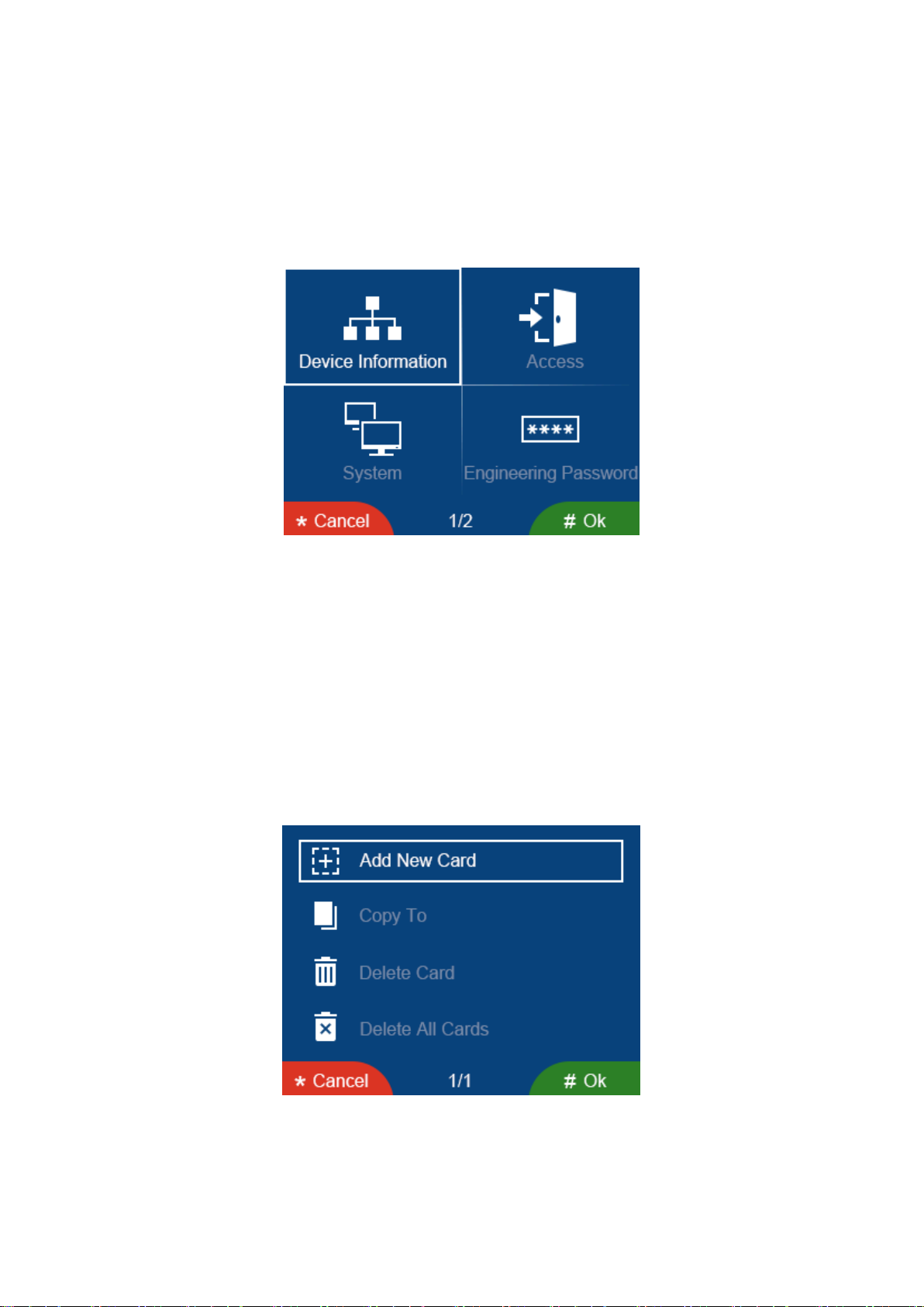
>> You can select the room number or input the room number you want to add and
then press “#”button, the screen will prompt “Swipe card to 1001”(1001 is room
number);
>> Move the card near the swipe card panel (one room can only add 5 cards);
※Copy Card
>> You can select the [copy to] item and then press “#”button to enter the door
panel list page;
>> You can select the door panel you want to copy to, then press “#”button to
confirm.
※Delete Card
>> You can select the [Delete Cards] item and then press “#”button to enter the
name list page, you can select the room number or input the room number you want
to delete and then press “#”button to confirm the delete;
>> You can select the [Delete All Cards] item and then press “#”button, the screen
will prompt “Delete all cards”and then press “#”button to confirm;
◆In [System] setting page, you can set the time & date, adjust the talking volume,
restore factory settings and engineering setting; you can also set the language of
the door panel, turn [Tamper Alarm] and [Voice Prompt] on or off, copy address
book(only the first door panel supports this function; only copy the door panel in
the same network).
>> If you set the [Voice Prompt] is ON:
When you press the 0, 1, 2…9 button and you will hear a voice prompt “zero, one,
two…nine”;
When you press the up or down button and you will hear a voice prompt “user list”
(only in main pages);

10
When you press the guard button and you will hear a voice prompt “security”(only in
main pages);
When you press the “#”or talk button and you will hear a voice prompt “calling”(only
in calling page);
When you unlock the card and you will hear a voice prompt “door opened”.
◆In [Engineering Password] setting page, you can set the engineering
password(the password is 4 digit).
◆In [About] setting page, you can review the Block No. / Device Id and HW Ver.
Remark:
Door panel support only ID card.
In any setting page, you can press “*”button to return to the previous setting
page.
The time & date of the first door panel will be synchronized to other device in
the system.
When you forget the engineering password, you can do the following
operation to restore to the default password: press the tamper button “*”
button tamper button “#”button (valid only on the main page and the
tamper alarm page; this operation must be completed within 3s).
6.4Unlock Function
There are two unlock types as the follows:
>> Password unlock: “#”button Unlock password “#”button;
>> Card unlock: When a user move the added card near the swipe card panel, the
door will be open.
Remark:
The password unlock function can be enabled/disabled in the access settings.
Swipe card distance ≤20mm.
Table of contents