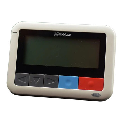
Multitone EKSHUB Service manual

Document Part Number: 9262-0119
Issue Number: 1
Release: 23/02/2022
EkoSecure Hub
DIN VDE V 0825-1 compliant
Product Part Number: EKSHUB
Administrator Guide

Contents 2
EkoSecure DIN VDE V 0825-1 compliant Hub Administrator Guide
9262-0119 Issue I
Contents
0Preface ______________________________________________________________ 7
0.1 About this document 7
0.2 Intended readers 7
0.3 Warranty 7
0.4 Compliance 7
0.5 Company liability 8
0.6 Data protection 8
0.7 Safety 8
0.7.1 Installation notes 9
0.7.2 Connection of power supplies 9
0.7.3 Servicing 9
0.8 Limitations 10
0.9 Feedback 10
0.10 Version control 10
1Introduction _________________________________________________________ 11
2Front panel __________________________________________________________ 11
2.1 Overview 11
2.2 Indicators 12
2.2.1 LCD Display screen 12
2.2.2 Timing synchronisation with Timing Master 12
2.2.3 Radio beacon transmission active 13
2.2.4 Configuration installed 13
2.2.5 EkoTek logo 13
2.3 Removing the lower front panel 13
2.3.1 IP Address Reset button 14
3Powering the device___________________________________________________ 15
3.1 Powering up the device 16
3.2 Powering down the device 16
3.2.1 Changing the on-board batteries 17
3.3 Failure of the external power supply 18
3.3.1 Total power failure 18
4Software interface ____________________________________________________ 18

Contents 3
EkoSecure DIN VDE V 0825-1 compliant Hub Administrator Guide
9262-0119 Issue I
4.1 Connecting a viewing device to the Hub 19
4.2 Accessing the web interface 19
4.2.1 Logging in to the web portal 20
4.2.2 Logging out of the web portal 20
5Konfiguration menu___________________________________________________ 21
5.1 System settings 21
5.1.1 System Clock 22
5.1.2 Hub IP settings 23
5.1.3 Connecting to external systems 24
5.1.4 Remote logging 25
5.1.5 LAN 227
5.2 Funk 28
5.2.1 Netzkennung 28
5.2.2 Synchronisation PTP domain 29
5.2.3 Frequenzsprung 29
5.2.4 Autoregistrierung Gerät 31
5.2.5 Autoregistrierung Name 31
5.3 Geräte 32
5.3.1 Manually adding a new device 33
5.3.2 Editing an existing device 35
5.3.3 Removing a device 35
5.4 Geräteprofil 35
5.4.1 Abstellruf settings [Fob devices] 37
5.4.2 Akusticher Alarm (drop-down list) 37
5.4.3 Alarm löschen settings [Pager devices] 37
5.4.4 Alarm Wiederholung – Intervall (text field) 38
5.4.5 Alarmbetrieb settings [Call Point devices] 38
5.4.6 Alarmbetrieb settings [Fob devices] 40
5.4.7 Anwesenheit settings 41
5.4.8 Assistenzalarm settings 42
5.4.9 Auf Netzwerk fixieren 42
5.4.10 Bereichsalarm settings 43
5.4.11 Bewohnerruf settings 44
5.4.12 Downstream-Kanal (drop-down list) 45
5.4.13 Freigabe zur Alarmlöschung (checkbox) 46
5.4.14 Funk (checkbox) 47
5.4.15 Kanal (drop-down list) 47
5.4.16 Kontakteingabe settings 48
5.4.17 Lagealarm settings 49
5.4.18 Lokalisierungbereich (drop-down list) 50
5.4.19 Manueller alarm settings 51
5.4.20 Notruf settings [EkoCare Units] 52
5.4.21 Nur Long-Range / Konvertor (radio buttons) 53
5.4.22 Reißleine settings 54

Contents 4
EkoSecure DIN VDE V 0825-1 compliant Hub Administrator Guide
9262-0119 Issue I
5.4.23 Relais-Betrieb settings 55
5.4.24 Schwesternruf settings [EkoCare Units] 56
5.4.25 Schwesternrufbetrieb settings [Call Point and Fob devices] 57
5.4.26 Upstream-Kanal (drop-down list) 58
5.4.27 Zeitalarm settings 60
5.5 Pagergruppen 60
5.5.1 Managing Pager Groups 61
5.6 Alarmregeln 63
5.6.1 Adding a new Alert Rule 65
5.6.2 Editing an existing Alert Rule 66
5.7 EkoCare Regeln 67
5.8 Zurücksetzen 67
5.9 Alles Löschen 68
5.10 Passworter 69
5.10.1 Editing the account passwords 70
5.10.2 Access based on user account 70
5.11 Datensicherung 71
5.11.1 Creating an archive 71
5.11.2 Restoring an archive into the system 72
5.12 Aktualisierung72
5.13 Herunterfahren 74
5.14 Nachrichtenformat 75
6Hauptmenu __________________________________________________________ 76
6.1 Tag / Nacht – Setting the current Shift 76
6.1.1 Manuelle Auswahl 76
6.1.2 Automaticsh 77
6.1.3 Extern 77
6.2 Ereignisprotokoll 78
6.2.1 The Event Log table 79
6.2.2 Adding records 80
6.2.3 Exporting the Event Log data 80
6.3 Nachricht senden 80
6.4 Nachrichtenprotokoll 81
6.4.1 The Nachrichtenprotokoll table 82
7Systeminfo menu _____________________________________________________ 83
7.1 Gerätestatus 83
7.1.1 Device Details page 84
7.2 Netzwerk-Baum 86
7.2.1 Searching the Network Tree 87
7.3 Verkehr 88
7.4 Rangfolge der Nachrichten 89

Contents 5
EkoSecure DIN VDE V 0825-1 compliant Hub Administrator Guide
9262-0119 Issue I
8Operating the hardware interface________________________________________ 90
8.1 Default display 90
8.2 Raising and clearing alarms 91
8.2.1 Raising an alarm from the Hub 91
8.2.2 Clearing an alarm raised by the Hub 92
8.2.3 Alarm escalation 92
8.3 Receiving messages 92
8.3.1 Responding to a message 92
8.3.2Messages listed on the default display 93
8.3.3 Receivable message types 93
8.4 Zeitalarm prompts 94
8.5 Hub operation menu 94
8.5.1 Hauptfunktionen 94
8.5.2 Zusatzfunktion 96
9Upgrading the Hub software ____________________________________________ 98
10 Servicing____________________________________________________________ 99
11 Additional support ____________________________________________________ 99
Appendices_________________________________________________________ 100
AEkoSecure principles 100
A.1 The radio network mesh 100
A.2 Beacons 101
A.2.1 Main Beacon 101
A.2.2 Location Beacon 103
A.3 Devices 104
A.3.1 The Hub 104
A.3.2 Static devices 105
A.3.3 Portable devices 106
A.3.4 External devices and systems 106
A.4 Device Modes overview 107
A.5 Network Zones overview 108
A.6 Alarms 108
A.6.1 Alarm types 108
A.6.2 Alarm escalation 109
A.6.3 Information included in alarm messages 109
A.6.4 Alert Rules overview 110
A.7 Maintenance Messages 110
BCompliance with DIN VDE V 0825-1 111
B.1 Response times 111
B.2 Pager identificantion in alarms 112

Contents 6
EkoSecure DIN VDE V 0825-1 compliant Hub Administrator Guide
9262-0119 Issue I
B.3 Monitoring and technical alarms 112
B.4 Pager operation 112
B.5 Alarm type test on Pager activation 113
B.6 Notification of personal alarms by the Hub 113
B.7 Manual clearance of audible and visible alerts 114
B.8 Internal and external logging of alarms 114
B.9 Independent power supplies 115
B.10 Fail-over power capability 115
B.11 Indication of external power failure 115
B.12 Product labelling 116
B.13 Enclosed user information 116
B.14 Electrical safety 117
CRemote logging ouput 117
Index ______________________________________________________________ 119

0 Preface 7
EkoSecure DIN VDE V 0825-1 compliant Hub Administrator Guide
9262-0119 Issue I
0 Preface
0.1 About this document
This document covers the full operational function and device management of the
EkoSecure DIN VDE V 0825-1 compliant Hub as part of a complete EkoSecure system
once installed and commissioned for use. Guidance on editing the system configuration is
also included.
The Hub contains a range of settings and features intended for use when EkoSecure is
integrated with a wider EkoTek system, which are covered in this document. Where
EkoSecure is installed as a self-contained system, these features do not apply.
For user guidance limited to basic operation of the hardware interface at Operator level for
daily team use, see the dedicated Operator Guides, document numbers 9262-0116
(German) and 9262-0117 (English).
For documentation concerning the installation of the devices, see the dedicated system
Installation & Setup Guide, document number 9261-9708.
For information on the role of other Devices within an EkoSecure system, see the
dedicated EkoSecure system documentation, available from Multitone upon request.
0.2 Intended readers
This document is intended for use by users with administrative and management
responsibilities relating to the EkoSecure system and access to the browser interface of the
EkoSecure Hub. Some technical knowledge and familiarity of the system is required.
0.3 Warranty
This Multitone system is supplied with a 12-month warranty beginning upon receipt of the
solution. Please see Multitone’s standard terms and conditions of purchase.
0.4 Compliance
EU Territories
This product complies with the requirements of the following EU Directives:
Radio Equipment Directive (RED) 2014/53/EU
RoHS-2 Directive 2011/65/EU (Decision 768/2008/EC
Annex II, Module A)
Product accreditation is also inclusive of certification by the German DGUV authority to the
following standards:

0 Preface 8
EkoSecure DIN VDE V 0825-1 compliant Hub Administrator Guide
9262-0119 Issue I
Surveillance systems - Radio staff protection systems
for Lone Workers, DIN VDE V 0825-1;
Use of personal emergency signal systems,
DGUV Regel 112-139
A complete copy of the associated Declaration of Conformity for this and other Multitone
products may be obtained upon request from info@multitone.de or
supportdesk@multitone.com. Alternatively, please contact your Multitone representative.
This equipment contains low power radio devices and has been tested for compliance with
the recognised operational performance and personnel safety working limits specified for
such equipment. Should any problems arise in relation to interference affecting signals
both to and from the equipment, the apparatus may require repositioning or the fitting of
additional filtering components, such as ferrite absorbers or in-line filters. Should such
action be deemed necessary, contact either Multitone or their authorised agents.
PRODUCT DISPOSAL WEEE DIRECTIVE & 2012/19/EU
At the end of its serviceable life, this product should not be treated
as household or general waste. It should be handed over to the
applicable collection point for the recycling of electrical and
electronic equipment, or returned to Multitone or their agent, for
disposal.
0.5 Company liability
This document has been compiled for guidance only and the content checked for technical
accuracy. The user should ensure that the correct issue of the document is used, as
Multitone Electronics plc will not accept any liability for inaccuracies or errors resulting from
its use.
In line with Multitone’s policy of continued technical advancement, technical specifications
are subject to change without notice. The products and services offered may be subject to
availability and differ from those described, or illustrated, in this document.
0.6 Data protection
As the equipment user or controller, you may collect and manage personnel data. In this
instance, you must be in compliance with any local privacy protection laws and regulations
that protect the rights and interests of other people, by implementing measures which
include but are not limited to: handling such data securely and only for a period of time that
is reasonably required for its intended use.
0.7 Safety
The following information applies to both operating and servicing personnel. General
Warnings and Cautions will be found throughout the manual where they apply.

0 Preface 9
EkoSecure DIN VDE V 0825-1 compliant Hub Administrator Guide
9262-0119 Issue I
WARNING statements identify conditions or practices that could result in personal
injury.
CAUTION statements identify conditions or practices that could result in physical
damage to the product or loss of data.
All the safety and operating instructions should be read before the equipment is connected
and operated and retained for future reference. All warnings marked on the equipment
should be strictly adhered to. No attempt should be made to remove any designated safety
covers, as these areas contain voltages of a sufficient magnitude to constitute a risk of
electric shock to personnel.
This package contains small parts that may be hazardous if mismanaged.
To attract attention, this equipment emits loud alert tones. Repeated exposure to such
sounds at close range can result in permanent hearing loss or damage. Users should
avoid putting their ears against the sounder opening on the front panel.
0.7.1 INSTALLATION NOTES
The installation and servicing of this product must only be carried out by suitably qualified
personnel.
This equipment is rated for use in the temperature range 0 - +40 ºC and is
ingress-rated to IP20. The equipment should be positioned away from sources of heat and
so that there is no interference to the flow of air around the front and sides of the unit.
This equipment has been designed to conform to the relevant Safety and EMC
performance standards, but it may be necessary to take additional precautions during
installation, to ensure continued compliance.
0.7.2 CONNECTION OF POWER SUPPLIES
This equipment is intended to be primarily powered by an external Power-over-Ethernet
(PoE) injector power supply. This should be connected to a nearby 100-240 V AC, 50 Hz
power source using the power cable supplied; see section 3.
This equipment also contains a re-chargeable backup battery installation. Any
replacement of these batteries should only be undertaken by designated service personnel.
0.7.3 SERVICING
This equipment should only be serviced at a Multitone approved service facility.
Other than the batteries, none of the components of this equipment can be replaced or
repaired by users. Only authorised dealers or service centres may dismantle the product.

0 Preface 10
EkoSecure DIN VDE V 0825-1 compliant Hub Administrator Guide
9262-0119 Issue I
If any parts of your product require replacement for any reason, including normal wear and
tear or breakage, contact your dealer.
0.8 Limitations
In accordance with the requirements stipulated by DIN VDE V 0825-1, some features and
settings relating to this model of the EkoSecure Hub are pre-configured or disabled by
default and cannot be changed. Information relating to these requirements is included in
Appendix B.
0.9 Feedback
Multitone welcomes feedback relating to this document and the product(s) described.
Please direct any comments to supportdesk@multitone.com or to Multitone’s Head Office:
Germany:
Multitone Elektronik
International GmbH
Roßstraße 11
D-40476 Düsseldorf
Deutschland
GB:
Multitone Electronics plc
Multitone House
Shortwood Copse Lane
Kempshott
Basingstoke
Hampshire
RG23 7NL
United Kingdom
0.10 Version control
Version 1 23/02/2022 First release

1 Introduction 11
EkoSecure DIN VDE V 0825-1 compliant Hub Administrator Guide
9262-0119 Issue I
1 Introduction
The EkoSecure Hub is a high-capacity control centre for EkoSecure systems through which the network
and connected devices can be managed, providing a radio network interface to EkoSecure repeaters
and a pair of LAN interfaces to TCP/IP-based equipment. The device is powered by either PoE or 12 V
DC, with failover to rechargeable batteries capable of covering power outages of 30 minutes or more.
2 Front panel
2.1 Overview
The following controls are available on the front panel interface:
Emergency Alarm button
Back button
Scroll button
Select / Enter button
The following indicators are located on the front panel interface:
LCD display screen
Timing synchronisation with
Timing Master
Radio beacon transmission
active
Configuration installed
Active power supply via PoE or
12 V DC connected
Use the Cover Release Clips to open the front panel of the Hub; see section 2.3.
E
A
B
G
F
H
C
Fig. 1 The EkoSecure Hub interface
I
J
D
A
B
C
D
E
F
G
H
I
J

2 Front panel 12
EkoSecure DIN VDE V 0825-1 compliant Hub Administrator Guide
9262-0119 Issue I
2.2 Indicators
The indicators on the front panel of the device convey the following information.
2.2.1 LCD DISPLAY SCREEN
The LCD display shows all messages received by the Hub and any available response
options. The number of message previews shown simultaneously on the display is limited
to 4.
The LCD will not illuminate until an active external power supply is connected and the
on-board batteries have charged to a level sufficient to complete a controlled power-down
procedure when the external supply is disabled.
Status icons
The following icons are displayed in the top-right corner of the Hub LCD display:
Connected to an active external power supply
Powered by the on-board battery
An approximate indication of the current level of charge is indicated
through the icon
An audible alert will be triggered when alarms and messages are received
The system configuration is currently using the Tag Shift settings
The system configuration is currently using the Nacht Shift settings
Device Operation Status indicator
The separator between the hours and minutes value of the display clock indicates correct
functionality of the Hub:
00 : 00 –The Hub is functioning correctly
00 ! 00 – The Hub processor has encountered a problem and the system is
inoperable
Contact your Multitone Agent for assistance
2.2.2 TIMING SYNCHRONISATION WITH TIMING MASTER
Where multiple systems are installed in close proximity, the radio signals of each system
must be assigned a separate PTP domain in order to prevent message conflicts and
overlaps between systems. Within each system, one Hub must be designated the Timing
Master to manage the signal timing for that system. This is managed in the Configuration
Fig. 2 The LCD display default screen

2 Front panel 13
EkoSecure DIN VDE V 0825-1 compliant Hub Administrator Guide
9262-0119 Issue I
settings; see section 5.2.2 for more information. This is configured by the system
Administrator. The Hub’s status as a Timing Master or Slave is indicated by the LED.
The Timing Synchronisation indicator illuminates in the following modes:
On – The Hub is configured as the system Timing Master, or is configured
as a slave device that is synchronised to a Timing Master within the system
Flashing – The Hub is configured as a slave device but is currently acting as
the Timing Master
Off – The Hub is configured as a slave device but is not synchronised to a
Timing Master within the system
The Timing Synchronisation indicator temporarily changes illumination mode to recognise a
press of the IP Address Reset button. After 60 seconds, the indicator returns to its original
mode.
2.2.3 RADIO BEACON TRANSMISSION ACTIVE
The radio beacon transmission is indicated by the icon.
During normal operation, this icon will flash to indicate that the Hub is creating and
broadcasting the system network. The icon will only remain unlit in the following
circumstances:
A factory reset or controlled power-down has been initiated
A system Archive is being restored
The device has suffered an error and is not operating correctly
2.2.4 CONFIGURATION INSTALLED
Illumination of the icon indicates that the Hub has received and applied its configured
settings. This occurs during start-up and the indicator should illuminate within 60 seconds
of the device powering on. The indicator remains illuminated during normal operation.
2.2.5 EKOTEK LOGO
When is illuminated, the device is connected to an active external power supply.
When powered only by the on-board batteries, this indicator is not lit.
2.3 Removing the lower front panel
To access the hardware interface connections, the lower front panel of the device casing
must be removed.
To remove the front panel:
a) Press the two Cover Release Clips inwards towards the device interior
b) Push the clips upwards and lift the front panel away from the device
J

2 Front panel 14
EkoSecure DIN VDE V 0825-1 compliant Hub Administrator Guide
9262-0119 Issue I
To replace the front panel, align and insert the casing tabs along the upper edge and press
the bottom of the panel to lock it in place.
2.3.1 IP ADDRESS RESET BUTTON
The button located between the two RS232 data ports beneath the removable lower
front panel can be used for the following purposes:
Resetting the IP address of the Hub
Performing a controlled power-down procedure
When pressed, the illumination of the Timing Synchronisation indicator changes for 60
seconds to acknowledge the action; see section 2.2.2.
PLEASE NOTE: Pressing the IP Address Reset button may disrupt the EkoSecure
system. It should only be pressed when safe to do so and when any disruption can be
managed accordingly.
Resetting the IP address of the Hub
To reset the IP address of the Hub to the default value of 192.168.1.2:
Fig 4. Locating the IP Reset button beneath the removable front panel
K
Fig. 3 Locating the Cover Release Clips
J
K

3 Powering the device 15
EkoSecure DIN VDE V 0825-1 compliant Hub Administrator Guide
9262-0119 Issue I
Press and hold the reset button for approximately 1 second
When User ‘super’ enabled is shown on the LCD display, press and hold
the reset button for another 2 seconds
The default IP address is shown on the LCD display
Once reset, the Hub can be accessed at its default address. The IP address of the of the
device adaptor used to access the Hub must be within the same range as this address.
An additional press of the IP address reset button after its use to reset the Hub’s IP
address will restore the Hub to its previously configured address. The configured address
is displayed on the LCD display.
Powering down the Hub using the IP Address Reset button
Pressing and holding the IP address reset button for at least 5 seconds will initiate a
controlled power-down of the device. Herunterfahren is shown on the LCD display when
the process is initiated. Once the message has appeared, wait for the power down
process to complete. This may take up to 30 seconds.
PLEASE NOTE: If the IP address reset button is used to power down the device, the LCD
display will switch off but the EkoTek logo will remain illuminated in order to
indicate an active external power supply. Removing and restoring the external power will
restart the device.
3 Powering the device
The EkoSecure Hub can be powered by a Power over Ethernet connection or through a 12 V DC
supply. PoE can be provided over Cat5e cabling by the supplied PoE Injector or a PoE-equipped
network switch.
The device must also have 4 Ni-MH AA rechargeable cells with a minimum capacity of 2.4 Ah installed
as an emergency supply in the event of external power failure. The device will only power on once the
AA batteries have reached enough charge to independently power the device long enough for a
controlled power-down procedure to be completed.
Fig. 5The connections available beneath the lower front panel of the Hub, with potential external power connections highlighted

3 Powering the device 16
EkoSecure DIN VDE V 0825-1 compliant Hub Administrator Guide
9262-0119 Issue I
CAUTION: Installed batteries MUST be Nickel-metal hydride with a minimum of 2.4 Ah capacity. DO
NOT install non-rechargeable batteries into the device. All 4 batteries must be installed before the
device can be used.
The Hub’s power connections can be accessed by removing the lower front panel.
3.1 Powering up the device
In the event that power must be manually restored to the Hub:
a) Press the Cover Release Clips and remove the lower front panel
b) Ensure that the 4 on-board batteries are installed
c) Identify the Hub’s external power source:
i) If the Hub is powered using Power over Ethernet (PoE):
1. Unplug and reconnect the Ethernet cable connected to the LAN 1
port
ii) If the Hub is powered using 12 V DC via the EXT Contacts:
1. Ensure the DC power connection is connected via a 12 V DC
power adapter to a mains power outlet
2. Switch on the mains power
d) The logo on the front panel illuminates when an active power supply is
connected
e) The front panel display illuminates once the on-board batteries have reached enough
charge to support a complete power-down procedure
i) If the on-board batteries are not sufficiently charged when external power is
connected, the Radio Beacon and Configuration indicators will
flash alternately while the device tests the battery state
3.2 Powering down the device
In the event that the Hub must be turned off, a controlled power-down procedure must be
initiated.
PLEASE NOTE: Powering down the Hub will disable the EkoSecure network.
To perform a controlled power-down procedure:
a) If the Hub web browser interface can be accessed easily:
i) Navigate to the Hub IP address and log in
ii) Navigate to Konfiguration > Herunterfahren; see section 5.13
iii) Select System Neustart or Herunterfahren from the drop-down menu as
appropriate
iv) Press BESTÄTIGEN to confirm the action
b) If the Hub web browser interface cannot be accessed easily:
i) Either:

3 Powering the device 17
EkoSecure DIN VDE V 0825-1 compliant Hub Administrator Guide
9262-0119 Issue I
1. Press and hold the IP address reset button until the LCD display
shows Herunterfahren
A. See section 2.3.1
ii) Or: 1. Disconnect or disable the PoE or 12 V DC power supply
A. The lower front panel must be removed to disconnect an
external power supply at the Hub interface; see section
2.3
2. Allow the on-board battery charge to be exhausted
A. This will take at least 30 minutes
3. When the battery charge is nearly exhausted, the Hub will
autonomously trigger a controlled power-down procedure
CAUTION: DO NOT remove the on-board batteries while the device is still powered if
there is no other power supply to the Hub. This will prevent the completion of a controlled
power-down procedure and may result in data corruption. The batteries should only be
removed when the device is no longer switched on.
3.2.1 CHANGING THE ON-BOARD BATTERIES
Over time the performance of the on-board backup batteries may deteriorate due to age or
frequent use. The batteries must be replaced by Nickel-metal hydride rechargeable AA
battery cells with a minimum capacity of 2.4 Ah, as supplied by Multitone.
To replace the on-board batteries:
Ensure that the Hub is connected to an active external power supply
The device must remain powered throughout the battery change
process to ensure that the new batteries are sufficiently charged to
support a power failure
Remove the front panel of the device
Remove ONLY the 2 batteries from the left-hand holder and replace with
new cells
Remove ONLY the 2 batteries from the right-hand holder and replace with
new cells
It is recommended that the batteries are replaced every 24 months to ensure sufficient
charge to support a power failure of at least 30 minutes.
CAUTION: NEVER install non-rechargeable batteries into the EkoSecure Hub. This may
cause damage to the device and render it unsafe. Replace all 4 batteries at the same
time. Always dispose of used batteries responsibly.

4 Software interface 18
EkoSecure DIN VDE V 0825-1 compliant Hub Administrator Guide
9262-0119 Issue I
3.3 Failure of the external power supply
In the event that the primary power supply of PoE or 12 V DC becomes inactive during
normal operation, the Hub performs the following actions:
Stromausfall is displayed on the Hub’s front panel display
A Stromausfall message is sent to all devices in Pager
Group 1
This message is accompanied by an audio tone from the Hub, if enabled in the LCD
display menu.
As the battery back-up power supply depletes, Batterie NIEDRIG messages are presented
on the Hub front panel display.
If the external power supply is not restored, the Hub will perform a controlled power-down
procedure to ensure that the system is switched off correctly.
3.3.1 TOTAL POWER FAILURE
In the event that both the external power supply fails and the on-board batteries are
exhausted, the Hub will perform a controlled power-down procedure. This will safely switch
off the device, but will disable the EkoSecure network until power is restored.
4 Software interface
The EkoSecure Hub can be configured and managed through a web interface accessible by any
browser-enabled device on the same network.
Functions such as adding system Devices, managing Alert Rules, and Hub maintenance must be
completed via the web interface. Initial configuration is completed during installation by the system
Engineer.
Fig. 6Hub external power failure as indicated on the LCD display
Fig. 7Low charge remaining in the Hub’s on-board batteries as indicated on the LCD display

4 Software interface 19
EkoSecure DIN VDE V 0825-1 compliant Hub Administrator Guide
9262-0119 Issue I
4.1 Connecting a viewing device to the Hub
To view the EKSHUB web interface, the device used for access must have an IP address
within the same network subnet as the Hub itself. The Hub has two individually
configurable LAN ports to which a static IP address can be assigned; see section 5.1.
Where the Hub is installed as part of a wider LAN or WAN, other devices on that network
may be able to access the Hub browser interface automatically through the network
connection.
Where the Hub is not installed as part of a wider LAN or WAN, a wired connection must be
made between the device used to access the web interface and one of the Hub’s LAN
ports. In this instance, the IPv4 settings of the Ethernet Adapter of the accessing device
may need to be manually set by the user. The IP Address, Subnet Mask, and Default
Gateway settings must be configured so that they are within the same range as those
configured for the connected Hub LAN port.
PLEASE NOTE: The Hub’s LAN 2 port can only be used if enabled in the system
configuration; see section 5.1.5.
4.2 Accessing the web interface
To access the Hub’s web interface, enter the IP address of the connected Hub LAN port
into the URL field of a browser on a device connected to the same network.
PLEASE NOTE: The default address of the Hub’s LAN 1 port is 192.168.1.2. This may
have been changed during initial configuration. To view the currently configured IP
address of the Hub, see section 8.5.1.
Fig. 8 The EkoSecure browser interface after login

4 Software interface 20
EkoSecure DIN VDE V 0825-1 compliant Hub Administrator Guide
9262-0119 Issue I
4.2.1 LOGGING IN TO THE WEB PORTAL
Login credentials are required when accessing the web portal during a new browser
session.
The Hub is configured with two user accounts by default, each with differing levels of
access privilege. See section 5.10 for login credentials and access restrictions.
4.2.2 LOGGING OUT OF THE WEB PORTAL
To log out of the web portal, either:
Click on the account name in the page header of the web portal interface
The browser returns to the portal log in page
Close the web browser fully on the viewing device
The browser will prompt for a new log in when the browser
reconnects to the Hub IP address
PLEASE NOTE: Automatic logout only occurs when the browser is no longer running on
the device. If only the active tab or window is closed but the browser continues to run, the
web portal will still be accessible without the need to log in.
Fig. 9 The EkoSecure login page on the browser interface
Fig. 10 To log out of the web interface, click the username at the top of the screen or fully close the web
browser on the device
Other manuals for EKSHUB
1
Table of contents
Other Multitone Switch manuals