multivac C 500 User manual
Instruction manual C 500
Betriebsanleitung 07.06.2005 1/43
ba_c500_50s2GB06IVZ.fm ega
Instruction manual C 500
Control panel
Betriebsanleitung 07.06.2005 2/43
ba_c500_50s2GB06IVZ.fm ega
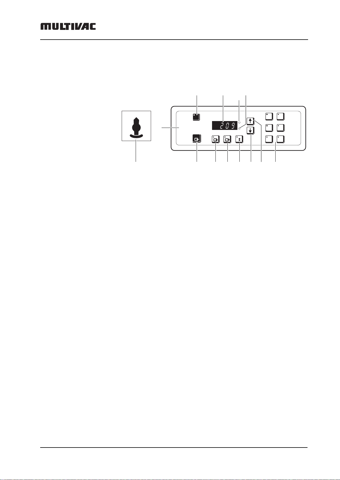
Control panel
1 Control panel, control unit
1.1 CONTROL UNIT ON/OFF key
1.2 Digital display
1.3 Display value in millibar
1.4 Display value in seconds
1.5 PROGRAM keys 1 to 6
1.6 INCREASE VALUE key
1.7 DECREASE VALUE key
1.8 SEALING key
1.9 INERT GAS key (optional)
1.10 VACUUM key
1.11 RAPID VACUUM STOP key
2 MACHINE ON/OFF main switch
mbar
s
STOP
P1 P2
P4P3
P5 P6
I/O
0
I
2
1
1.11 1.10 1.9 1.8 1.7 1.6 1.5
1.1 1.2 1.31.4

Elements of the machine
Betriebsanleitung 07.06.2005 3/43
ba_c500_50s2GB06IVZ.fm ega
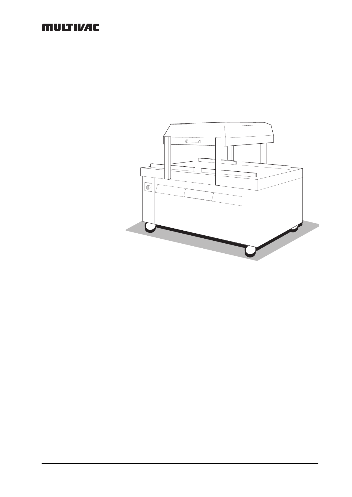
Elements of the machine
Front view
Back view (back wall removed)
1 Control panel, control unit
2 Main switch
3 Sealing bars
4 Cover seal
5 Counter-pressure bars
6 Inert gas nozzles
7 Compressed air connection
8 Inert gas connection
9 Water outlet
10 Water inlet
11 Electrical connection
12 Electrical connection
13 Vacuum pump oil filling screw
14 Vacuum pump oil inspection glass
15 Oil cooler drain screw
16 Vacuum pump oil drain screw
1
2
3
4
5
6
7
8
9
10 11
12
13
14
15
16

Elements of the machine
Betriebsanleitung 07.06.2005 4/43
ba_c500_50s2GB06IVZ.fm ega
Contents
Instruction manual C 500 ..................................................... 1
Control panel ......................................................................... 2
Elements of the machine ...................................................... 3
Manufacturer, service address, user information .............. 5
Use ......................................................................................... 6
Safety ..................................................................................... 7
Electromagnetic Compatibility (EMC) ............................................ 8
Operation with inert gas .................................................................. 8
Transport, Set-up, Putting into operation ........................... 9
External vacuum connection (Option) ......................................... 11
Cooling water connection (optional) ............................................ 12
Pressurised air connection ........................................................... 14
Inert gas connection ...................................................................... 15
Operation ............................................................................. 16
Packing – First steps ..................................................................... 16
Start up ............................................................................................ 16
Recommended Settings ................................................................... 17
Check pouch .................................................................................... 22
Displaying values, changing values ............................................ 24
Pressure indicator ............................................................................ 24
Displaying or changing the post-evacuation time ............................ 25
Displaying or changing the sealing time .......................................... 26
Displaying or changing separation time ........................................... 27
Displaying or changing the inert gas value ...................................... 28
Calling up or saving a program .................................................... 29
Care and maintenance ........................................................ 31
Cleaning .......................................................................................... 32
Disinfection - Corrosion protection ............................................. 33
Care products ................................................................................. 34
Replacing the cover seal ............................................................... 35
Trouble-shooting ................................................................ 36
Technical data ..................................................................... 39
Special equipment .............................................................. 40
MHP-evacuation time ..................................................................... 40
Working area sound pressure level .................................. 42
Assembly instructions, repair kit, sealing equipment ..... 43
Manufacturer, service address, user information
Betriebsanleitung 07.06.2005 5/43
ba_c500_50s2GB06.fm ega
Manufacturer, service address, user information
Manufacturer:
MULTIVAC
Sepp Haggenmüller GmbH & Co. KG
D-87787 Wolfertschwenden
Tel.: (08334) 601- 0
Fax: (08334) 601- 199
E-mail: [email protected]
Machine type:
C 500
Machine number:
(See type plate)
(please enter yourself)
Version number control:
(see control nameplate)
V 03_02_0, V 03_03_0
Note: These instruction manual applies to the versions above. In the case
of replacement of control, check version number and if this deviates, order
the correct instruction manual from MULTIVAC customer service.
Service address:
(To be filled in by agent or service)
Notes for the reader
Safety information – Where should I be particularly careful?
Information - what else is to be said
Copying or lending of this instruction manual or extracts thereof to third
parties is only allowed with the express permission of MULTIVAC.
i

Use
Betriebsanleitung 07.06.2005 6/43
ba_c500_50s2GB06.fm ega
Use
Proper use
This machine is a technical work tool designed to be used exclusively for
work.
It is to be used solely for packing products in pre-manufactured film
pouches which are closed with a seal seam.
For specifications, see the section "Technical data".
Any different or further application is not considered appropriate use and
can pose a hazard to persons, products and the machine.
Inappropriate use (misuse)
This machine is not suitable for the following:
– Aseptic packaging of products.
– Operation in rooms where there is the risk of explosions occurring.
–Gas flushing film pouches with gas mixtures containing more than 21%
oxygen.
Misuse excludes the manufacturer from any liability! The risk is
borne by the plant operator alone.
Avoidable incorrect use
– Use of externally purchased articles, e.g. non-original MULTIVAC
spare parts.
– Incorrect operation. Example: Sealing times that are too short or too
long result in the film pouches not being closed securely and thus
damage the product.
– Neglect of the required inspections, cleaning or servicing work.
Residual risks
The safety instructions in this manual are intended as work safety
guidelines for qualified machine operators. MULTIVAC cannot however
foresee all situations in which a hazard can arise. The machine safety
instructions and warnings in this operating manual can therefore not be
considered all-embracing. The plant operator and machine operator
remain responsible for safety.
Safety
Betriebsanleitung 07.06.2005 7/43
ba_c500_50s2GB06.fm ega
Safety
General Safety Notes
Dangerous contact voltage!
Making contact with voltage-carrying parts can lead to severe
injury, even death.
Only qualified electricians are permitted to make repairs to the
electrical equipment.
Switch off the machine before conducting any repair work.
Turn the main switch to 0 and lock it to prevent accidental
start-up.
Danger of burns!
The sealing bar can be hot.
Do not touch the sealing bar during operation.
When working on the sealing bar, allow the sealing bar to cool
or wear protective gloves.
Maintenance work on the sealing unit
Danger of burns!
The sealing bar can be hot!
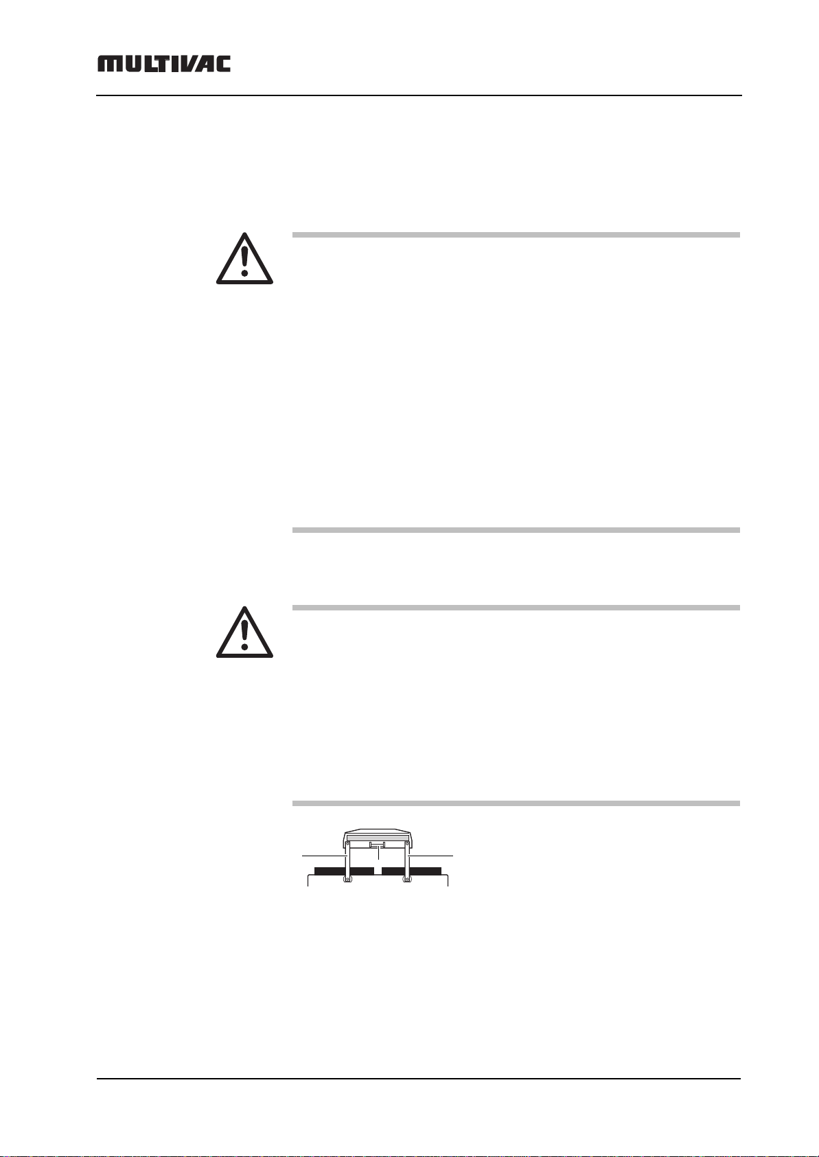
Danger!
There is a danger of injuries due to the swinging movement of
the cover.
Do not permit other persons to remain in the danger area!
Lid movements only to be carried out by pressing the hand
grip (1), not with the levers (2).
22
1
Safety
Betriebsanleitung 07.06.2005 8/43
ba_c500_50s2GB06.fm ega
Electromagnetic Com-
patibility (EMC) Chamber machines are designed for use in domestic, business and trade
sectors (without the use of an individual transformer, running from the pub-
lic electric power supply). If employed in the industrial sector, a limitation of
the operating characteristics may occur. In comparison to employment in
the domestic, business and trade sectors it is therefore possible that the
quality of operation may additionally suffer.
Operation with inert
gas
For machine with an inert gas system, the packs can be gas flushed after
evacuation.
Which inert gasses are used?
The inert gasses nitrogen (N2) and carbon dioxide (CO2) are components
of the natural atmosphere. They are recognised as harmless. They re-
place the previously removed air in the packs. Therefore one speaks of an
exchanged atmosphere.
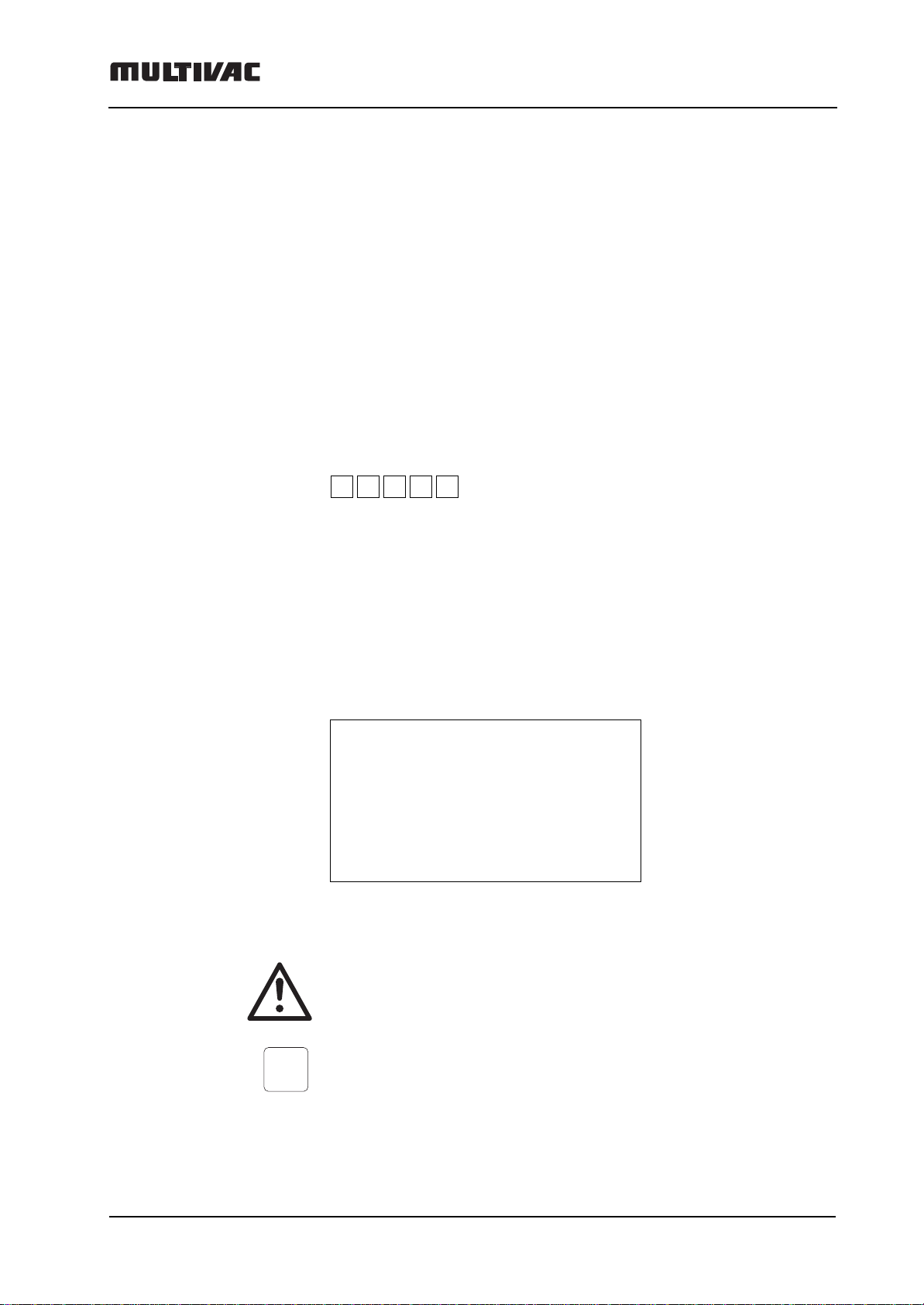
Risk of explosions!
Aeration with O2> 21 % is not permitted!
This warning sign is located near the gas
connection:
Do not use inflammable gas.
Danger of suffocation!
Inert gas is odourless!
Ventilate rooms well, do not allow pockets of gas to form!
Observe national safety regulations concerning its use.
The initial pressure must not exceed 3.
Shut off the gas supply after completing work.
> 21%
0
2
81.981.5118.30

Transport, Set-up, Putting into operation
Betriebsanleitung 07.06.2005 9/43
ba_c500_50s2GB06.fm ega
Transport, Set-up, Putting into operation
Set-up
– Note the weight of the machine, see "Technical data".
– Use suitable lifting equipment or have somebody else to assist you.
– Unpack the machine.
– Check there has been no damage caused during transport.
– Fill the vacuum pump with the oil (can) supplied.
– Check the oil level with the inspection glass.
Correct oil level between min. and max.
–After the oil has been poured in, the machine may only be levelly trans-
ported; the maximum gradient is 15°.
There are air de-oiling elements in the vacuum pump.
At an increased gradient the oil will move into the vacuum pump. Pos-
sible consequences:
– Air de-oiling components are wetted with oil and therefore become
unserviceable; this can be recognized by the presence of a strong
oil mist.
– The vacuum pump will be damaged.
max.
min.
max. 15°

Transport, Set-up, Putting into operation
Betriebsanleitung 07.06.2005 10/43
ba_c500_50s2GB06.fm ega
Electrical Connection
– Read the nominal voltage from the nameplate. Does it conform to the
power supply voltage?
If the rotational directon is incorrect, the vacuum pump can be destroyed,
so:
– switch it off immediately!
– reverse the 2 phases of the supply line (only by a qualified electrician).
– Check the rotational direction of the vacuum pump.
(Arrow on the vacuum pump motor).
Hz
A
kW
A
Netzsicherung
External fuse
Typ/Model
Ser. No.
Bauj./Year
V
Table of contents
Other multivac Kitchen Appliance manuals


Popular Kitchen Appliance manuals by other brands

Tayama
Tayama TYG-35AF instruction manual

AEG
AEG 43172V-MN user manual

REBER
REBER Professional 40 Use and maintenance

North American
North American BB12482G / TR-F-04-B-NCT-1 Assembly and operating instructions

Presto
Presto fountain popper instruction manual

Westmark
Westmark 1035 2260 operating instructions


