4 Description of psp Family
Rectifiers
4.1 Basic Information
Psp family switching-mode power supply
rectifiers stand out because of their compact
design, high control accuracy, low ripple, low
weight, and a high efficiency.
In contrast to other electronic rectifiers, such
as thyristor rectifiers, the ripple of psp family
power supplies is constant. Thus, psp family
rectifiers generate high quality direct currents.
As the operating frequency of the switching
mode power supply rectifiers is higher than
20 kHz the wound components, such as main
transformer and smoothing filter, as well as
the capacitors can be designed much smaller
while generating the same output power.
Another outstanding characteristic is the
improved dynamic response of the output
values which allow set point value deviations
at the DC voltage output to be adjusted within
milliseconds. These specific control
properties render the output variables very
stable.
The control accuracy of the internal closed-
loop control amounts to just 1% referring to
the nominal voltage or current. The current
and voltage ripple values of the DC output
are below 1 –3% of the nominal values
across the entire control range, if not
indicated otherwise in the technical
specification.
The power section is installed in an enclosure
made from insulating material, thus
preventing direct access to live components.
Psp family rectifiers are DC power supplies
designed on the basis of switching-mode
power supply technology. The internal control
electronics facilitate very short adjustment
times in case of sudden load variations.
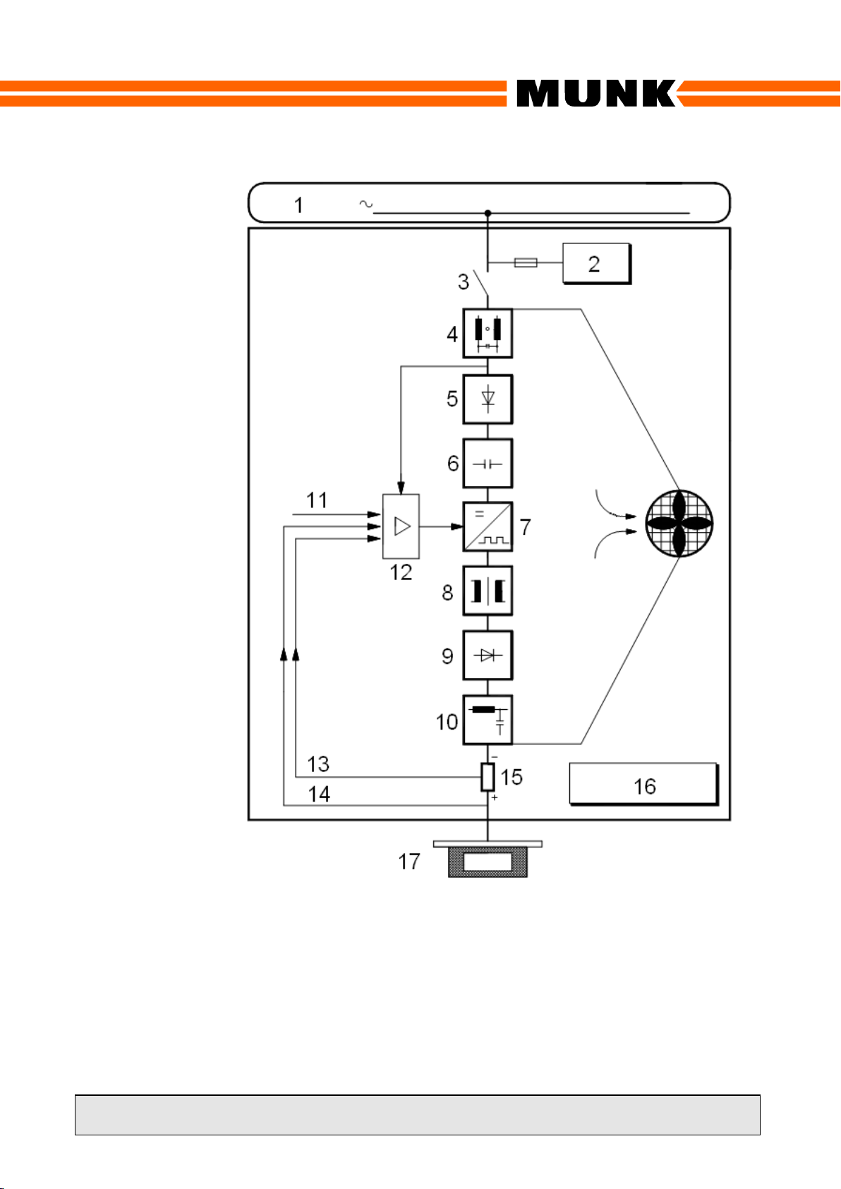
4.2 Switching Mode Power Supply
Technology
Switching-mode power supply technology
rectifies the mains voltage and supplies it to a
DC link consisting of capacitors and
connected to a high frequency inverter, which
converts the DC link voltage into an AC
voltage of a higher frequency. This AC
voltage is transferred to the transformer
primary circuit, which adjusts the voltage and
implements electrical isolation. The
secondary voltage of the transformer is
rectified and transferred via an output filter to
the rectifier output.
4.3 High Current Circuit
The high-current circuit includes the
transformer secondary circuit, a high-current
rectifier and a smoothing filter.
The high-current rectifier consists of rapid-
high-current diodes. The received DC voltage
is transferred via the smoothing filter to the
rectifier output. The smoothing filter filters the
superimposed high-frequency AC voltage of
the high-current rectifier. This allows a low-
ripple DC voltage to be applied to the rectifier
output.
4.4 Closed-Loop Control
Psp family rectifiers, are equipped with
current and voltage controllers. Owing to the
internal connection the controller limiting the
output variable is always the active one.
Therefore, you can only preset current and
voltage set point values or adjust them using
the potentiometers.
The rectifier operates according to a
controlled voltage/current characteristic to
DIN 41773.