Murata PE25200 User manual

http://www.murata.com/products/power
Copyright ©2021 Murata Manufacturing Co., Ltd. and pSemi Corporation, a Murata Company. All rights reserved.
DOC-105510-1 (07/2021)
Page 1 of 25
PE25200 Evaluation Kit (EVK)
User’s Manual
10A High Efficiency
Vin 5.5—10V Divide-by-2
Vin 8.2—15V Divide-by-3
DC-DC Converter

PE25200 EVK User’s Manual
High Efficiency DC-DC Converter
http://www.murata.com/products/power
Copyright ©2021 Murata Manufacturing Co., Ltd. and pSemi Corporation, a Murata Company. All rights reserved.
DOC-105510-1 (07/2021)
Page 2 of 25
Introduction
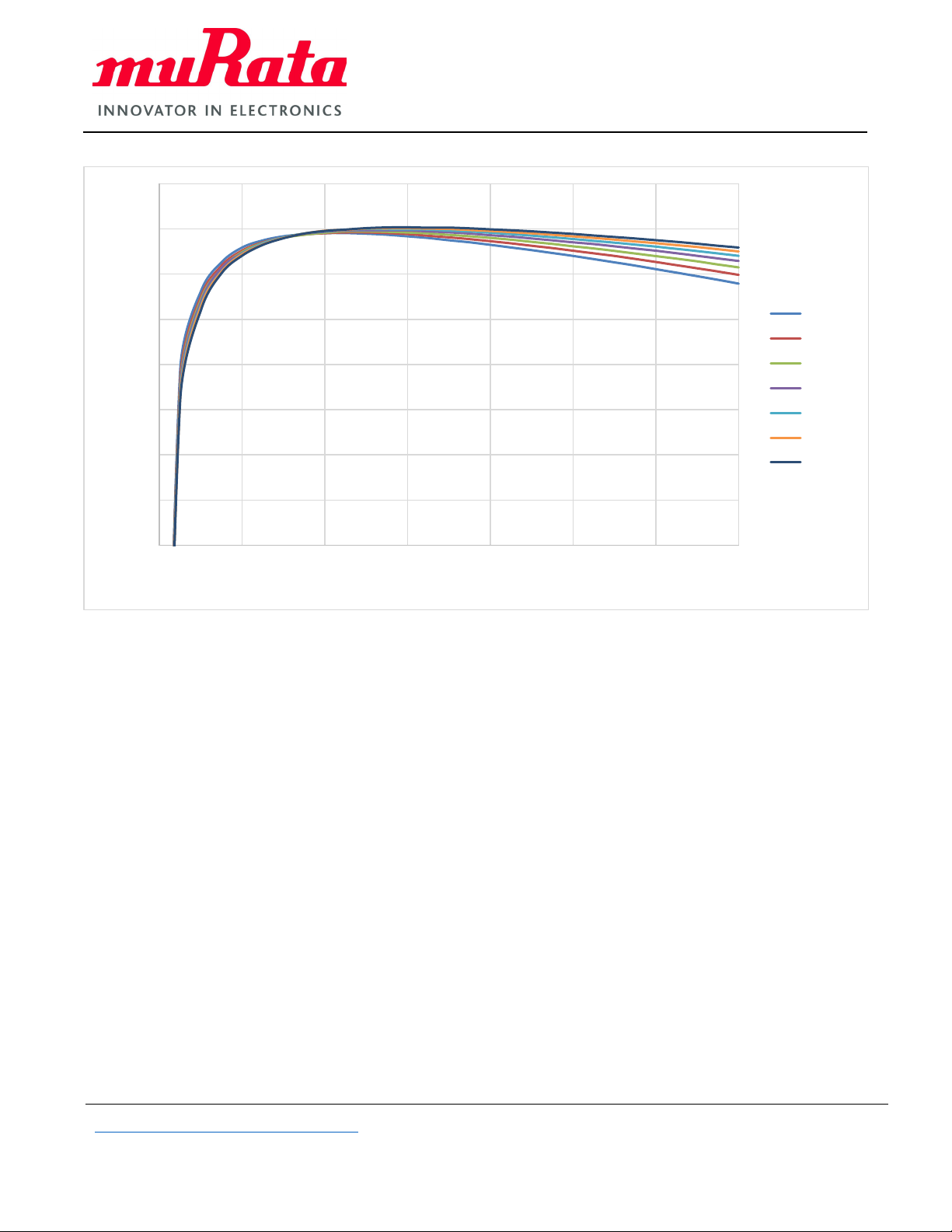
The PE25200 is an ultra-high efficiency DC-DC converter solution that divides down an input voltage by either a
factor of 2 or 3 and delivers up to 45W output at up to 95.4% peak efficiency. The PE25200 supports an input
voltage range of 15V max in divide-by-3 mode or 10V max in divide-by-2 mode and is available in a WLCSP
package.
Evaluation Kit Overview
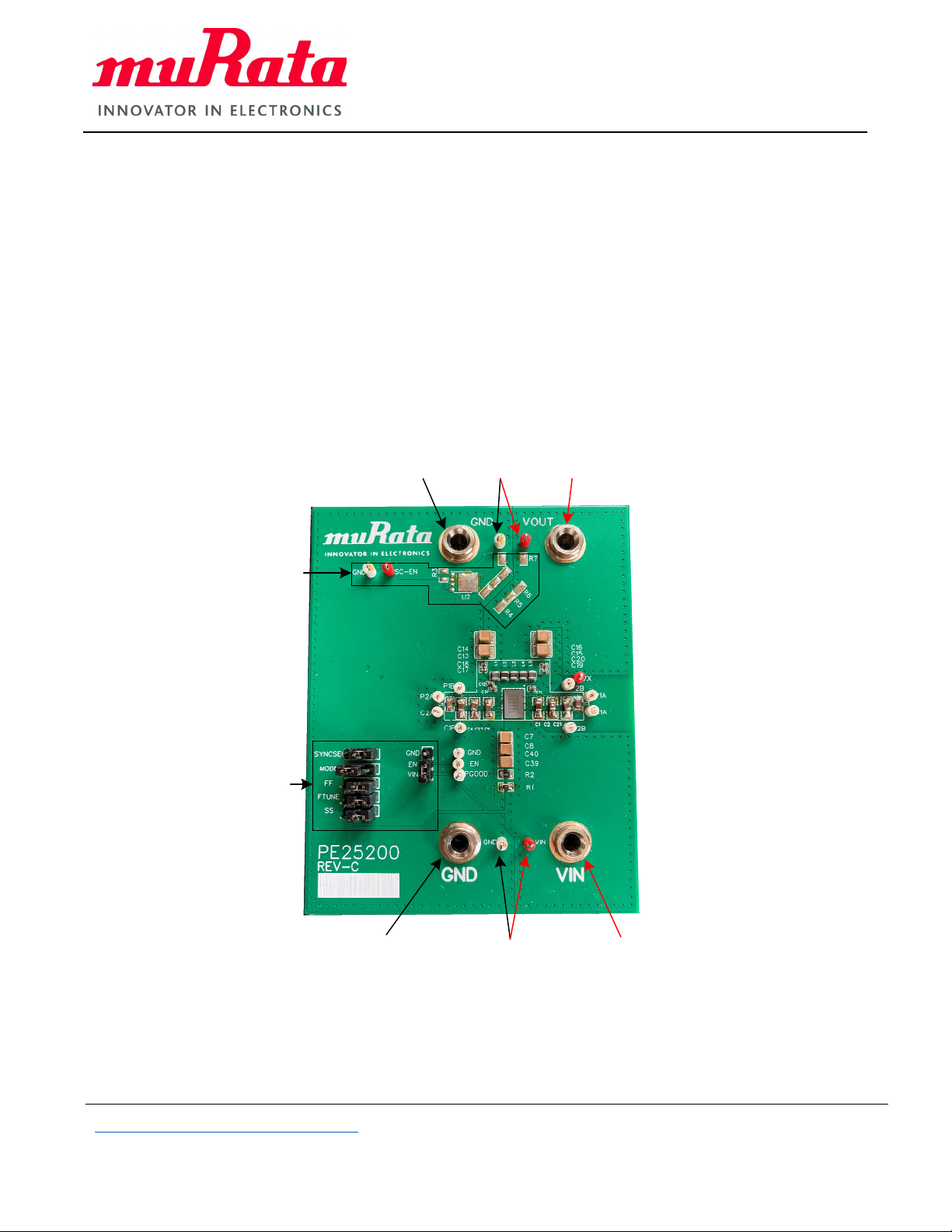
The PE25200 evaluation kit (EVK) is a hardware platform that allows customers to test the step-down DC-DC
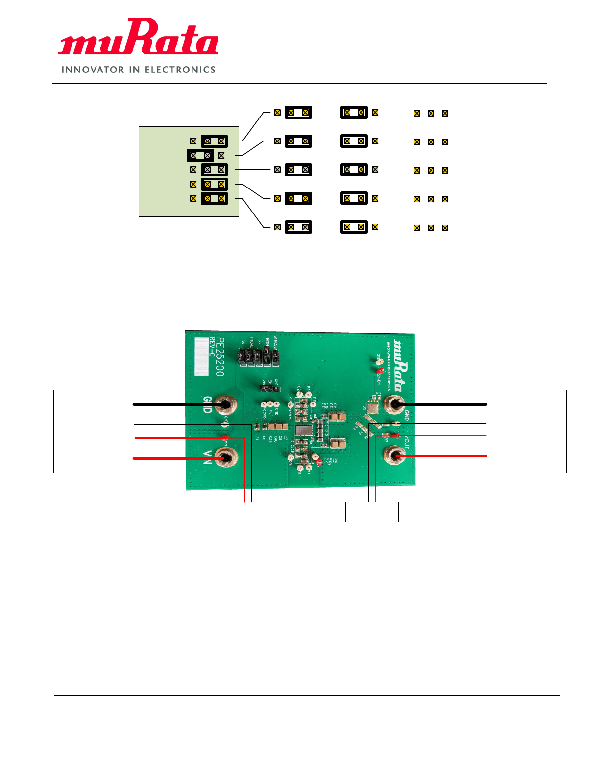
converter. High-current connections are via 4 mm sockets (banana plug style) with test hoops for connecting
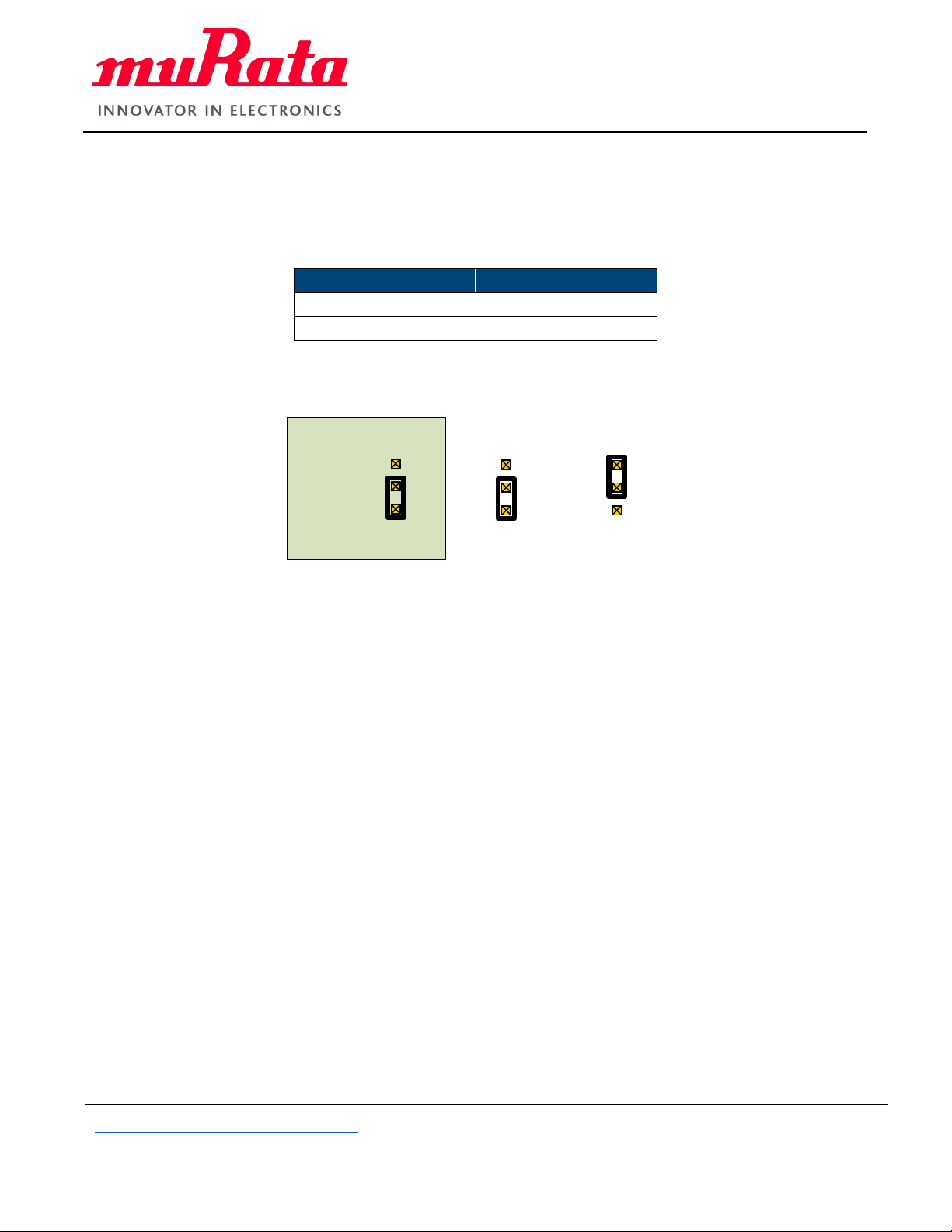
sensing and test equipment probes. A number of customer-adjustable links can be used to invoke alternate
operational modes.
Evaluation Kit User’s Manual Overview
This user’s manual includes information about the external hardware required to control and evaluate the
functionality of the DC-DC converter.
Evaluation Kit Contents and Requirements
Kit Contents
The PE25200 EVK includes the following hardware platform required to evaluate the DC-DC converter.
QUANTITY DESCRIPTION
1 PE25200 DC-DC converter evaluation board assembly (PE25200 REV-C)
Table 1. Evaluation Kit Contents
Hardware Requirements
In order to evaluate the performance of the evaluation board, the following equipment is required:
■
Bench supply capable of providing 10V–15V at 5A minimum with sense lines
■
Two digital multi-meters
■
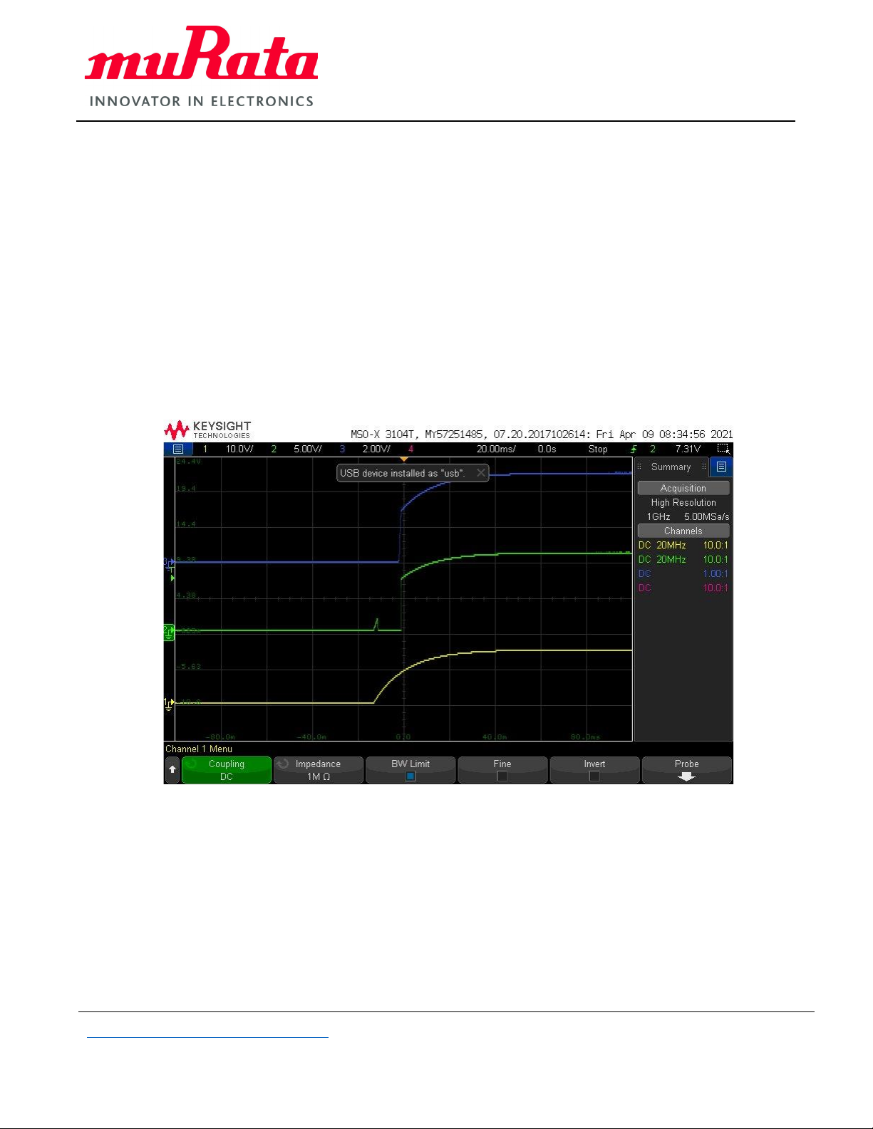
Four-channel oscilloscope with probes (optional to view waveforms)
■
Electrical load
Caution: The PE25200 DC-DC converter EVK contains components that might be damaged by exposure to
voltages in excess of the specified voltage, including voltages produced by electrostatic discharges. Handle the
board in accordance with procedures for handling static-sensitive components. Avoid applying excessive voltages
to the power supply terminals or signal inputs or outputs.
In particular, note that the input is at the bottom of the board marked in bold GND and VIN.
When connecting the EVK to the source power supply, ensure the power supply is off. Connecting the EVK to a
live power supply unit may cause failures. Ensure the output load is disconnected.

PE25200 EVK User’s Manual
High Efficiency DC-DC Converter
http://www.murata.com/products/power
Copyright ©2021 Murata Manufacturing Co., Ltd. and pSemi Corporation, a Murata Company. All rights reserved.
DOC-105510-1 (07/2021)
Page 3 of 25
Quick Start Guide
Quick Start Overview
The evaluation board is designed to ease customer evaluation of the PE25200 DC-DC converter. This section
guides you through configuring the hardware and the startup procedures.
Evaluation Board Overview
The evaluation board is designed to ease customer evaluation of Murata’s products. The board contains:
■
Input/output terminals
■
Test point hoops for voltage sense points and connection of voltmeters, oscilloscopes, etc.
■
Jumper links for changing the mode of operation
Vinsense
points
+Vin
connector
‐Vin
connector
Voutsense
points
+Vout
(load)
connector
‐Vout
(load)
connector
On‐boardload
Notequipped
Jumper
linkarray
INPUT
TERMINALS
Figure 1. PE25200 Evaluation Board Assembly

PE25200 EVK User’s Manual
High Efficiency DC-DC Converter
http://www.murata.com/products/power
Copyright ©2021 Murata Manufacturing Co., Ltd. and pSemi Corporation, a Murata Company. All rights reserved.
DOC-105510-1 (07/2021)
Page 4 of 25
Jumper Link Array Settings
The EN (Enable) link settings allow on-board control to enable the EVK by connecting the EN pin directly to the VIN
potential. The EN pin may be driven externally by connecting a potential between EN and GND.
.
VIN FUNCTION
< 0.4V Disabled
> 1.3V Enabled
Table 2. VIN and Enable Function
GND
EN
VIN
EVKEnabled EVKDisabled
Figure 2. EN Jumper Link Settings
Other jumper links allow for:
■
SYNCSEL—Not functional for this version of the EVK.
■
Mode—Sets the VIN to VOUT ratio by divide-by-2 or divide-by-3. Note: VIN divide-by-2 max = 10V; divide-by-
3 max = 15V.
■
FF—Sets fixed, asynchronous or cycle skip operation. Note: All pins open have functionality.
■
FTUNE—Sets nominal, plus 15% or minus 15% of operational frequency. Note: All pins open have
functionality.
■
SS—Sets the soft start current at 600 mA, 2.1A or 1.1A. . Note: All pins open have functionality.

PE25200 EVK User’s Manual
High Efficiency DC-DC Converter
http://www.murata.com/products/power
Copyright ©2021 Murata Manufacturing Co., Ltd. and pSemi Corporation, a Murata Company. All rights reserved.
DOC-105510-1 (07/2021)
Page 5 of 25
SYNCSEL
MODE
FF
FTUNE
SS
Fixedfrequency Asynchronous Cycleskip
Divideby2Divideby3Nofunction
Nofunction Nofunction Nofunction
Nominal 15% ‐15%
600mA 2.1A 1.1A
Figure 3. Typical Jumper Settings and Options
EVK Connection
Connect the EVK and the measuring equipment as shown in Figure 4.
Adjustable
benchpower
supply
15Vmax5A +Ve
‐Ve
+Vesense
‐Vesense Adjustable
electronicload
+Ve
‐Ve
+Vesense
‐Vesense
DMM DMM
Figure 4. EVK Connectors

PE25200 EVK User’s Manual
High Efficiency DC-DC Converter
http://www.murata.com/products/power
Copyright ©2021 Murata Manufacturing Co., Ltd. and pSemi Corporation, a Murata Company. All rights reserved.
DOC-105510-1 (07/2021)
Page 6 of 25
Hardware Operation
The general guidelines for operating the hardware evaluation board are listed in this section. Follow the steps below
to configure the hardware properly for the stated performance.
1. Ensure the jumpers are set as appropriate for the desired mode and division ratio.
2. Provide input voltage to the input terminals.
3. Apply output load after PGOOD goes high.
Figure 5 shows typical startup sequence traces.
■
Yellow trace = 15V from source
■
Green trace = PGOOD
■
Blue trace = Vout
Figure 5. Typical Startup Sequence
EVK Startup
When starting the EVK, be sure to start it with no load.
If the EVK is powered up with a load, it may not start due to the soft-start current limit being exceeded.

PE25200 EVK User’s Manual
High Efficiency DC-DC Converter
http://www.murata.com/products/power
Copyright ©2021 Murata Manufacturing Co., Ltd. and pSemi Corporation, a Murata Company. All rights reserved.
DOC-105510-1 (07/2021)
Page 7 of 25
Test Results
The following test results show the typical performance of the PE25200 evaluation board.
Figure 6. Divide-by-2 Internal Sync Efficiency vs. Output Current
60
65
70
75
80
85
90
95
100
012345678910
Efficiency (%)
Current (A)
Vin = 5V
Vin = 6V
Vin = 7V
Vin = 8V
Vin = 9V
Vin = 10V

PE25200 EVK User’s Manual
High Efficiency DC-DC Converter
http://www.murata.com/products/power
Copyright ©2021 Murata Manufacturing Co., Ltd. and pSemi Corporation, a Murata Company. All rights reserved.
DOC-105510-1 (07/2021)
Page 8 of 25
Figure 7. Divide-by-2 Internal Sync Cycle Skip Efficiency vs. Output Current
60
65
70
75
80
85
90
95
100
012345678910
Efficiency (%)
Current (A)
Vin = 5V
Vin = 6V
Vin = 7V
Vin =8V
Vin = 9V
Vin = 10V

PE25200 EVK User’s Manual
High Efficiency DC-DC Converter
http://www.murata.com/products/power
Copyright ©2021 Murata Manufacturing Co., Ltd. and pSemi Corporation, a Murata Company. All rights reserved.
DOC-105510-1 (07/2021)
Page 9 of 25
Figure 8. Divide-by-2 Internal Sync Async Efficiency vs. Output Current
60
65
70
75
80
85
90
95
100
012345678910
Efficiency (%)
Current (A)
Vin = 5V
Vin = 6V
Vin = 7V
Vin = 8V
Vin = 9V
Vin = 10V

PE25200 EVK User’s Manual
High Efficiency DC-DC Converter
http://www.murata.com/products/power
Copyright ©2021 Murata Manufacturing Co., Ltd. and pSemi Corporation, a Murata Company. All rights reserved.
DOC-105510-1 (07/2021)
Page 10 of 25
Figure 9. Divide-by-3 Internal Sync Efficiency vs. Output Current
60
65
70
75
80
85
90
95
100
02468101214
Efficiency (%)
Output current (A)
Vin 9V
Vin 10V
Vin 11V
Vin 12V
Vin 13V
Vin 14V
Vin 15V

PE25200 EVK User’s Manual
High Efficiency DC-DC Converter
http://www.murata.com/products/power
Copyright ©2021 Murata Manufacturing Co., Ltd. and pSemi Corporation, a Murata Company. All rights reserved.
DOC-105510-1 (07/2021)
Page 11 of 25
Figure 10. Divide-by-3 Internal Sync Cycle Skip Efficiency vs. Output Current
60
65
70
75
80
85
90
95
100
02468101214
Efficiency (%)
Current (A)
Vin 9V
Vin 10V
Vin 11V
Vin 12V
Vin 13V
Vin 14V
Vin 15V

PE25200 EVK User’s Manual
High Efficiency DC-DC Converter
http://www.murata.com/products/power
Copyright ©2021 Murata Manufacturing Co., Ltd. and pSemi Corporation, a Murata Company. All rights reserved.
DOC-105510-1 (07/2021)
Page 12 of 25
Figure 11. Divide-by-3 Internal Sync Async Efficiency vs. Output Current
60
65
70
75
80
85
90
95
100
02468101214
Efficiency (%)
Current (A)
Vin = 9V
Vin = 10V
Vin = 11V
Vin = 12V
Vin = 13V
Vin = 14V
Vin = 15V

PE25200 EVK User’s Manual
High Efficiency DC-DC Converter
http://www.murata.com/products/power
Copyright ©2021 Murata Manufacturing Co., Ltd. and pSemi Corporation, a Murata Company. All rights reserved.
DOC-105510-1 (07/2021)
Page 13 of 25
Figure 12. Output Ripple Divide-by-3, No Load
Figure 13. Output Ripple Divide-by-3, 10A

PE25200 EVK User’s Manual
High Efficiency DC-DC Converter
http://www.murata.com/products/power
Copyright ©2021 Murata Manufacturing Co., Ltd. and pSemi Corporation, a Murata Company. All rights reserved.
DOC-105510-1 (07/2021)
Page 14 of 25
Figure 14. 15V Input Noise, No Load
Figure 15. 15V Output Noise, No Load

PE25200 EVK User’s Manual
High Efficiency DC-DC Converter
http://www.murata.com/products/power
Copyright ©2021 Murata Manufacturing Co., Ltd. and pSemi Corporation, a Murata Company. All rights reserved.
DOC-105510-1 (07/2021)
Page 15 of 25
Figure 16. 15V Input Noise, 10A
Figure 17. 15V Output Noise, 10A

PE25200 EVK User’s Manual
High Efficiency DC-DC Converter
http://www.murata.com/products/power
Copyright ©2021 Murata Manufacturing Co., Ltd. and pSemi Corporation, a Murata Company. All rights reserved.
DOC-105510-1 (07/2021)
Page 16 of 25
Figure 18 shows a 1A to 9A dynamic load applied at 1 kHz. The output voltage variation is typically 400 mV.
TransientLoad
OutputVoltage
LoadCurrent
0
2
4
6
8
10
Amps
3
5
4
Volts
OutputVo lt age
LoadCurrent
Figure 18. Transient Load Response

PE25200 EVK User’s Manual
High Efficiency DC-DC Converter
http://www.murata.com/products/power
Copyright ©2021 Murata Manufacturing Co., Ltd. and pSemi Corporation, a Murata Company. All rights reserved.
DOC-105510-1 (07/2021)
Page 17 of 25
Information
PE25200 EVK PCB Layout
Figure 19. Evaluation Board Layout (Top)

PE25200 EVK User’s Manual
High Efficiency DC-DC Converter
http://www.murata.com/products/power
Copyright ©2021 Murata Manufacturing Co., Ltd. and pSemi Corporation, a Murata Company. All rights reserved.
DOC-105510-1 (07/2021)
Page 18 of 25
Figure 20. Evaluation Board Layout (Inner 1)

PE25200 EVK User’s Manual
High Efficiency DC-DC Converter
http://www.murata.com/products/power
Copyright ©2021 Murata Manufacturing Co., Ltd. and pSemi Corporation, a Murata Company. All rights reserved.
DOC-105510-1 (07/2021)
Page 19 of 25
Figure 21. Evaluation Board Layout (Inner 2)

PE25200 EVK User’s Manual
High Efficiency DC-DC Converter
http://www.murata.com/products/power
Copyright ©2021 Murata Manufacturing Co., Ltd. and pSemi Corporation, a Murata Company. All rights reserved.
DOC-105510-1 (07/2021)
Page 20 of 25
Figure 22. Evaluation Board Layout (Bottom)
Table of contents