Section 10 00-020165
08-25-10 - 2 -
Wiring and Adjustment Information
One Thermocouple Only
Even though the MDTM89 is a dual temperature monitor, it will monitor and display one temperature with equal
results.
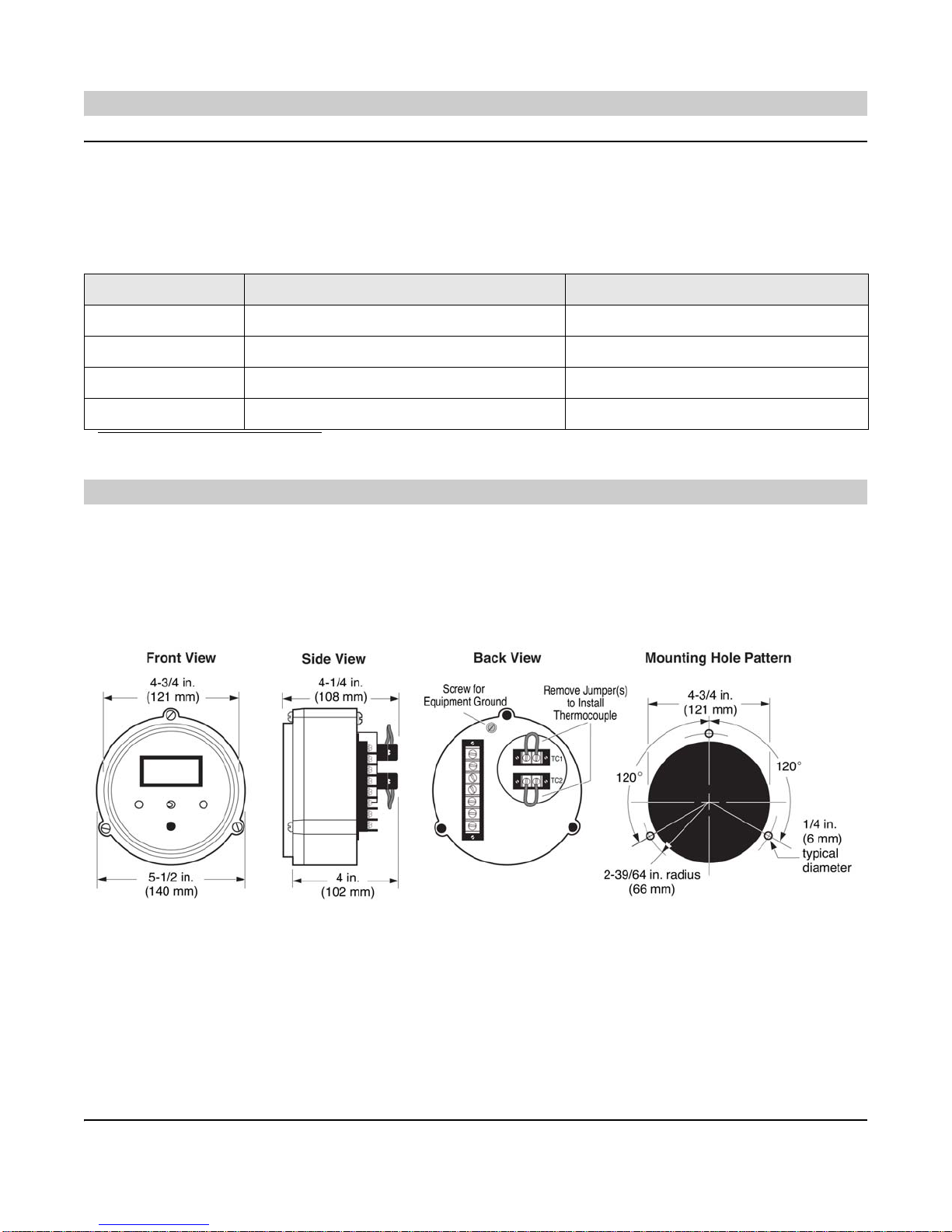
When monitoring one temperature, always jumper the unused thermocouple terminals on the back of the MDTM89
with a short length of wire. The unused channel will display approximate ambient temperature.
Open Thermocouple Input
An open thermocouple input forces the monitor into upscale overrange. The monitor indicates an overrange by dis-
playing the numeral “1” in the left most digit of the display. An overrange will turn on the trip point output, for the
respective thermocouple.
MDTM89 Wiring and Adjustment Instructions
A. Using Thermocouple Extension Wire
1. After thermocouple installation, connect the thermocouple leads to the MDTM89 according to the instruc-
tions.
2. If the thermocouple leads are not long enough you will need to use shielded thermocouple extension wire.
The thermocouple extension wires, from your thermocouple lead wires to the terminals of the MDTM89,
must be of the same material as the thermocouple lead wires. (See Table 1.)
3. When connecting the thermocouple extension wire to your thermocouple leads, twist the wire connections,
then install wire nuts, such as ceramic type, which have no metal insert. DO NOT SOLDER.
To prevent problems of interference from electrical noise, DO NOT route thermocouple wires in the same
conduit or within 12 inches (304 mm) of ignition wires or alternating current conductors.
Metallic-overbraided, thermocouple wire is recommended. It provides electrical shielding as well as protec-
tion against wear and abrasion.
CAUTION: Perform the wiring operation with the power source “OFF”. Make
sure the voltage and current requirements are within the SWICHGAGE® rat-
ings. Keep all high voltage wiring, such as spark plug wires away from THER-
MOCOUPLES AND EXTENSION WIRING. Before wiring determine the voltage
and polarity for the application.
Table 1. Thermocouple Extension Wire Color Code
Thermocouple
Type Thermocouple
Extension Wire Color Code/Material
Positive Lead Negative Lead
JJxWhite/Iron Red/Constantan
K Kx Yellow/Chromel Red/Alumel
Table 2. Thermocouple Extension Wire Loop
Resistance in Ohms per Foot at 68°F
Size AWG No. Type “J” Type “K”
14 .07 .146
16 .137 .230
18 .222 .374
20 .357 .586
24 .878 1.490
IMPORTANT: Use correct wire for the thermocouple selected. USE ONLY
THERMOCOUPLE EXTENSION WIRE.
CAUTION: The use of non thermocouple wire will cause inaccurate tempera-
ture sensing and erratic operation.