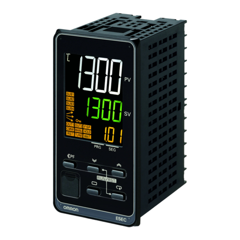
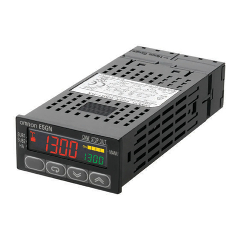
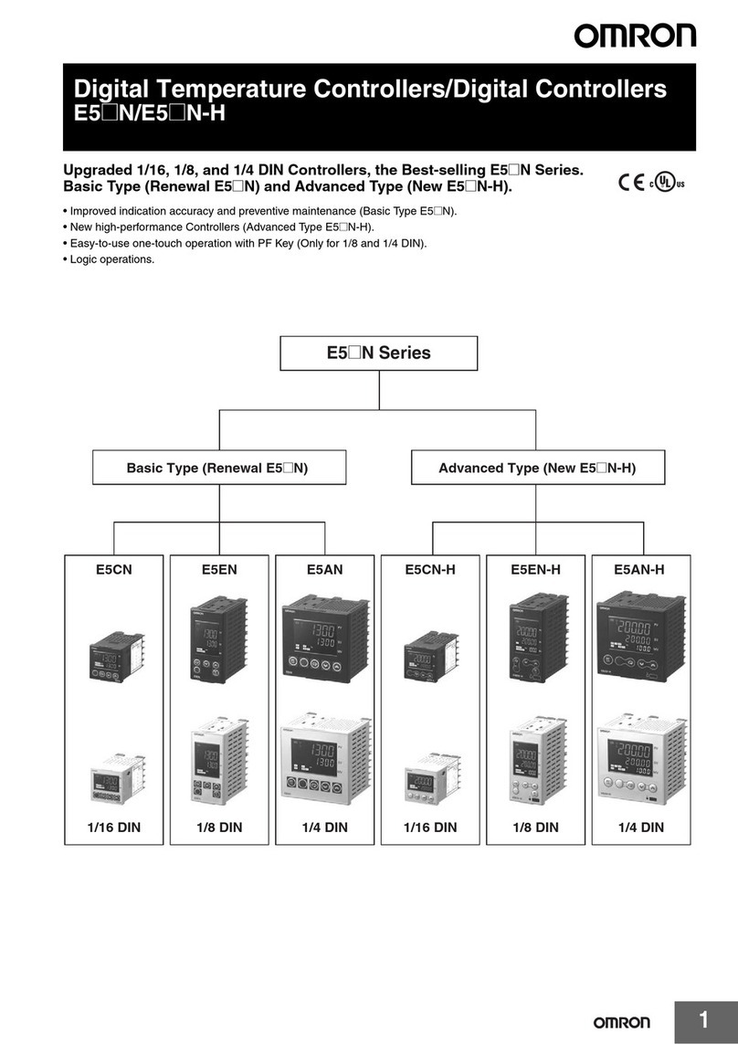
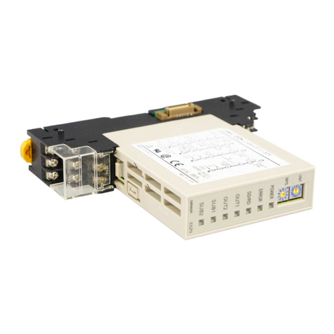
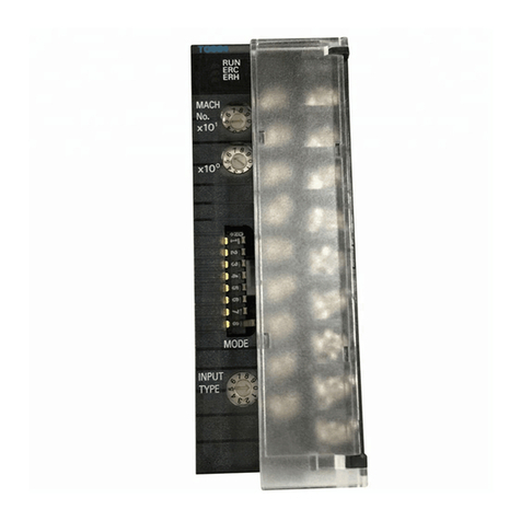
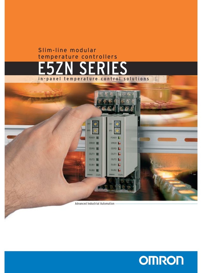
Omron E5ZN Series User manual

OPERATION MANUAL
Cat. No. H113-E1-1
E5ZN
Temperature Controller

E5ZN Temperature Controller
Operation Manual
Produced January 2001

iv

v
Notice:
OMRON products are manufactured for use according to proper procedures by a qualified operator
and only for the purposes described in this manual.
The following conventions are used to indicate and classify precautions in this manual. Always heed
the information provided with them. Failure to heed precautions can result in injury to people or dam-
age to property.
!DANGER Indicates an imminently hazardous situation which, if not avoided, will result in death or
serious injury.
!WARNING Indicates a potentially hazardous situation which, if not avoided, could result in death or
serious injury.
!Caution Indicates a potentially hazardous situation which, if not avoided, may result in minor or
moderate injury, or property damage.
Visual Aids
The following headings appear in the left column of the manual to help you locate different types of
information.
Note Indicates information of particular interest for efficient and convenient opera-
tion of the product.
1,2,3... 1. Indicates lists of one sort or another, such as procedures, checklists, etc.
ÓOMRON, 2001
All rights reserved. No part of this publication may be reproduced, stored in a retrieval system, or transmitted, in any form, o
r
by any means, mechanical, electronic, photocopying, recording, or otherwise, without the prior written permission o
f
OMRON.
No patent liability is assumed with respect to the use of the information contained herein. Moreover, because OMRON is con-
stantly striving to improve its high-quality products, the information contained in this manual is subject to change without
notice. Every precaution has been taken in the preparation of this manual. Nevertheless, OMRON assumes no responsibility
for errors or omissions. Neither is any liability assumed for damages resulting from the use of the information contained in
this publication.

vi
Abbreviations
The following table lists the main abbreviations used in parameters, diagrams, and in the text itself.
Note Scaled data is expressed in °C, m, g, and other engineering units. EU is used
as the minimum unit for engineering units For example, the smallest unit of
50.02 (m) is 0.01 (m) and 0.01 is thus one EU.
Parameter Notation
The following table shows the alphabet notation used for parameter abbreviations and settings dis-
played on the E5ZN-SDL Setting Display Unit.
Abbreviation Meaning
PV Process value
SP Set point
AT Autotuning
EU Engineering units (See note.)
ch Channel
abcdefghijklm
ABCDEFGHI JKLM
nopqrstuUwxy=
NOPQRSTUVWXYZ

vii
TABLE OF CONTENTS
PRECAUTIONS . . . . . . . . . . . . . . . . . . . . . . . . . . . . . . . . xiii
1 Intended Audience . . . . . . . . . . . . . . . . . . . . . . . . . . . . . . . . . . . . . . . . . . . . . . . . . xiv
2 General Precautions . . . . . . . . . . . . . . . . . . . . . . . . . . . . . . . . . . . . . . . . . . . . . . . . xiv
3 Application Precautions . . . . . . . . . . . . . . . . . . . . . . . . . . . . . . . . . . . . . . . . . . . . . xiv
SECTION 1
Outline . . . . . . . . . . . . . . . . . . . . . . . . . . . . . . . . . . . . . . . . 1
1-1 Name and Function of Parts . . . . . . . . . . . . . . . . . . . . . . . . . . . . . . . . . . . . . . . . . . 2
1-2 I/O Configuration and Main Functions. . . . . . . . . . . . . . . . . . . . . . . . . . . . . . . . . . 4
SECTION 2
Preparations . . . . . . . . . . . . . . . . . . . . . . . . . . . . . . . . . . . 7
2-1 Installation. . . . . . . . . . . . . . . . . . . . . . . . . . . . . . . . . . . . . . . . . . . . . . . . . . . . . . . . 8
2-2 Using the I/O Section . . . . . . . . . . . . . . . . . . . . . . . . . . . . . . . . . . . . . . . . . . . . . . . 13
2-3 Installation Precautions. . . . . . . . . . . . . . . . . . . . . . . . . . . . . . . . . . . . . . . . . . . . . . 18
SECTION 3
Temperature Control Settings. . . . . . . . . . . . . . . . . . . . . 21
3-1 Setting the Input Type. . . . . . . . . . . . . . . . . . . . . . . . . . . . . . . . . . . . . . . . . . . . . . . 22
3-2 Selecting °Centigrade/°Farenheit . . . . . . . . . . . . . . . . . . . . . . . . . . . . . . . . . . . . . . 23
3-3 Selecting PID Control or ON/OFF Control . . . . . . . . . . . . . . . . . . . . . . . . . . . . . . 24
3-4 Setting Output Specifications . . . . . . . . . . . . . . . . . . . . . . . . . . . . . . . . . . . . . . . . . 25
3-5 Setting the SP . . . . . . . . . . . . . . . . . . . . . . . . . . . . . . . . . . . . . . . . . . . . . . . . . . . . . 27
3-6 Executing ON/OFF Control . . . . . . . . . . . . . . . . . . . . . . . . . . . . . . . . . . . . . . . . . . 28
3-7 Determining PID Constants: Autotuning and Manual Setup . . . . . . . . . . . . . . . . . 30
3-8 Alarm Outputs. . . . . . . . . . . . . . . . . . . . . . . . . . . . . . . . . . . . . . . . . . . . . . . . . . . . . 32
3-9 Using Heater Burnout Alarm (HBA) . . . . . . . . . . . . . . . . . . . . . . . . . . . . . . . . . . . 35
3-10 Starting and Stopping Control. . . . . . . . . . . . . . . . . . . . . . . . . . . . . . . . . . . . . . . . . 37
3-11 Operating Precautions. . . . . . . . . . . . . . . . . . . . . . . . . . . . . . . . . . . . . . . . . . . . . . . 38
SECTION 4
Settings Used Only when Required. . . . . . . . . . . . . . . . . 39
4-1 Shifting Input Values. . . . . . . . . . . . . . . . . . . . . . . . . . . . . . . . . . . . . . . . . . . . . . . . 40
4-2 Alarm Hysteresis. . . . . . . . . . . . . . . . . . . . . . . . . . . . . . . . . . . . . . . . . . . . . . . . . . . 44
4-3 Setting Scaling Upper and Lower Limits (Analog Input). . . . . . . . . . . . . . . . . . . . 46
4-4 Executing Heating and Cooling Control. . . . . . . . . . . . . . . . . . . . . . . . . . . . . . . . . 47
4-5 Using the Event Input . . . . . . . . . . . . . . . . . . . . . . . . . . . . . . . . . . . . . . . . . . . . . . . 48
4-6 Setting the SP Upper and Lower Limit Range . . . . . . . . . . . . . . . . . . . . . . . . . . . . 50
4-7 SP Ramp Function: Limiting SP Change Rate . . . . . . . . . . . . . . . . . . . . . . . . . . . . 51
4-8 Key Protection. . . . . . . . . . . . . . . . . . . . . . . . . . . . . . . . . . . . . . . . . . . . . . . . . . . . . 52
4-9 Manual Mode . . . . . . . . . . . . . . . . . . . . . . . . . . . . . . . . . . . . . . . . . . . . . . . . . . . . . 54
4-10 Reading Temperatures for Multiple E5ZN Units . . . . . . . . . . . . . . . . . . . . . . . . . . 56
4-11 Remote PV Mode . . . . . . . . . . . . . . . . . . . . . . . . . . . . . . . . . . . . . . . . . . . . . . . . . . 57
viii
TABLE OF CONTENTS
SECTION 5
Communications . . . . . . . . . . . . . . . . . . . . . . . . . . . . . . . . 59
5-1 Communication Protocols . . . . . . . . . . . . . . . . . . . . . . . . . . . . . . . . . . . . . . . . . . . 60
5-2 Data Format Structure . . . . . . . . . . . . . . . . . . . . . . . . . . . . . . . . . . . . . . . . . . . . . . 61
5-3 Structure of Command/Response Text . . . . . . . . . . . . . . . . . . . . . . . . . . . . . . . . . 63
5-4 Variable Area. . . . . . . . . . . . . . . . . . . . . . . . . . . . . . . . . . . . . . . . . . . . . . . . . . . . . 64
5-5 Read from Variable Area. . . . . . . . . . . . . . . . . . . . . . . . . . . . . . . . . . . . . . . . . . . . 65
5-6 Write to Variable Area. . . . . . . . . . . . . . . . . . . . . . . . . . . . . . . . . . . . . . . . . . . . . . 66
5-7 Operation Commands . . . . . . . . . . . . . . . . . . . . . . . . . . . . . . . . . . . . . . . . . . . . . . 67
5-8 Setting Areas . . . . . . . . . . . . . . . . . . . . . . . . . . . . . . . . . . . . . . . . . . . . . . . . . . . . . 69
5-9 Commands and Responses . . . . . . . . . . . . . . . . . . . . . . . . . . . . . . . . . . . . . . . . . . 70
5-10 Variable Area Map. . . . . . . . . . . . . . . . . . . . . . . . . . . . . . . . . . . . . . . . . . . . . . . . . 85
SECTION 6
Using the E5ZN-SDL. . . . . . . . . . . . . . . . . . . . . . . . . . . . . 97
6-1 Introduction . . . . . . . . . . . . . . . . . . . . . . . . . . . . . . . . . . . . . . . . . . . . . . . . . . . . . . 98
6-2 Names of Parts on the Front Panel. . . . . . . . . . . . . . . . . . . . . . . . . . . . . . . . . . . . . 100
6-3 Setup Level Configuration and Front Panel Keys . . . . . . . . . . . . . . . . . . . . . . . . . 102
6-4 Initial Setup Examples. . . . . . . . . . . . . . . . . . . . . . . . . . . . . . . . . . . . . . . . . . . . . . 104
6-5 Using Copy Mode . . . . . . . . . . . . . . . . . . . . . . . . . . . . . . . . . . . . . . . . . . . . . . . . . 107
6-6 List of Parameters . . . . . . . . . . . . . . . . . . . . . . . . . . . . . . . . . . . . . . . . . . . . . . . . . 108
SECTION 7
Parameters. . . . . . . . . . . . . . . . . . . . . . . . . . . . . . . . . . . . . 111
7-1 Conventions Used in this Chapter . . . . . . . . . . . . . . . . . . . . . . . . . . . . . . . . . . . . . 113
7-2 Protect Level . . . . . . . . . . . . . . . . . . . . . . . . . . . . . . . . . . . . . . . . . . . . . . . . . . . . . 114
7-3 Operation Level. . . . . . . . . . . . . . . . . . . . . . . . . . . . . . . . . . . . . . . . . . . . . . . . . . . 115
7-4 Adjustment Level. . . . . . . . . . . . . . . . . . . . . . . . . . . . . . . . . . . . . . . . . . . . . . . . . . 121
7-5 Initial Setting Level . . . . . . . . . . . . . . . . . . . . . . . . . . . . . . . . . . . . . . . . . . . . . . . . 128
7-6 Advanced Function Setting Level . . . . . . . . . . . . . . . . . . . . . . . . . . . . . . . . . . . . . 135
7-7 Communications Setting Level . . . . . . . . . . . . . . . . . . . . . . . . . . . . . . . . . . . . . . . 145
SECTION 8
Troubleshooting. . . . . . . . . . . . . . . . . . . . . . . . . . . . . . . . . 147
8-1 Troubleshooting Procedure . . . . . . . . . . . . . . . . . . . . . . . . . . . . . . . . . . . . . . . . . . 148
8-2 Communications Errors. . . . . . . . . . . . . . . . . . . . . . . . . . . . . . . . . . . . . . . . . . . . . 149
8-3 Temperature Sensing Errors . . . . . . . . . . . . . . . . . . . . . . . . . . . . . . . . . . . . . . . . . 150
8-4 Temperature Control Errors. . . . . . . . . . . . . . . . . . . . . . . . . . . . . . . . . . . . . . . . . . 152
8-5 Output Errors. . . . . . . . . . . . . . . . . . . . . . . . . . . . . . . . . . . . . . . . . . . . . . . . . . . . . 154
8-6 HB Alarm Errors . . . . . . . . . . . . . . . . . . . . . . . . . . . . . . . . . . . . . . . . . . . . . . . . . . 155

ix
TABLE OF CONTENTS
Appendices
A Specifications . . . . . . . . . . . . . . . . . . . . . . . . . . . . . . . . . . . . . . . . . . . . . . . . . . . . . 157
B Error Displays. . . . . . . . . . . . . . . . . . . . . . . . . . . . . . . . . . . . . . . . . . . . . . . . . . . . . 161
C Sensor Input Setting Ranges/Control Ranges. . . . . . . . . . . . . . . . . . . . . . . . . . . . . 163
D ASCII Table . . . . . . . . . . . . . . . . . . . . . . . . . . . . . . . . . . . . . . . . . . . . . . . . . . . . . . 165
Index. . . . . . . . . . . . . . . . . . . . . . . . . . . . . . . . . . . . . . . . . . 167
Revision History . . . . . . . . . . . . . . . . . . . . . . . . . . . . . . . . 171

x

xi
About this Manual:
This manual describes how to use the E5ZN and includes the sections described below.
Before using your E5ZN, thoroughly read and understand this manual in order to ensure correct use.
Also, store this manual in a safe place so that it can be accessed whenever necessary.
The E5ZN Temperature Controller allows the user to perform the following:
• Control temperature for two channels with one Temperature Controller. The Temperature Controller
can be expanded to control up to 32 channels.
• Use an E5ZN-SDL Setting Display Unit to set the Temperature Controller.
• Input non-contact temperature sensors, analog voltages, thermocouples, or platinum-resistance ther-
mometers.
• Select heating/cooling control in addition to standard control.
• Select autotuning as the tuning function.
• Use multi-SP and a RUN/STOP function with event inputs.
• Use a HBA (heater burnout alarm).
• Use communications.
The E5ZN conforms to UL/CSA/ICE safety standards and EMC standards.
Precautions provides general precautions for using the E5ZN.
Section 1 describes E5ZN features, part names, and main functions.
Section 2 describes mounting, wiring, and other preparatory work that must be done before the E5ZN
can be used.
Section 3 describes the basic settings required by the E5ZN.
Section 4 describes scaling, SP ramp, and other functions to enable maximum use of the E5ZN func-
tions.
Section 5 describes performing communications for the E5ZN.
Section 6 describes how to operate the E5ZN-SDL Setting Display Unit.
Section 7 describes the parameters used to control E5ZN operation.
Section 8 classifies problems by situation and describes the methods for checking any possible mal-
functions.
!WARNING Failure to read and understand the information provided in this manual may result in per-
sonal injury or death, damage to the Temperature Controller, or product failure. Please
read each section in its entirety and be sure you understand the information provided in
the section and related sections before attempting any of the procedures or operations
given.

xii

xiii
PRECAUTIONS
This section provides general precautions for using the E5ZN Temperature Controller.
The information contained in this section is important for the safe and reliable application of the Temperature
Controller. You must read this section and understand the information contained before attempting to set up or
operate an Temperature Controller.
1 Intended Audience . . . . . . . . . . . . . . . . . . . . . . . . . . . . . . . . . . . . . . . . . . . . . xiv
2 General Precautions . . . . . . . . . . . . . . . . . . . . . . . . . . . . . . . . . . . . . . . . . . . . xiv
3 Application Precautions . . . . . . . . . . . . . . . . . . . . . . . . . . . . . . . . . . . . . . . . . xiv

xiv
Intended Audience 1
1 Intended Audience
This manual is intended for the following personnel, who must also have
knowledge of electrical systems (an electrical engineer or the equivalent).
• Personnel in charge of installing automation systems.
• Personnel in charge of designing automation systems.
• Personnel in charge of managing automation systems and facilities.
2 General Precautions
The user must operate the Temperature Controller according to the perfor-
mance specifications described in the operation manuals.
Before using the Temperature Controller under conditions which are not
described in the manual or applying the Temperature Controller to nuclear
control systems, railroad systems, aviation systems, vehicles, combustion
systems, medical equipment, amusement machines, safety equipment, and
other systems, machines, and equipment that may have a serious influence
on lives and property if used improperly, consult your OMRON representative.
Make sure that the ratings and performance characteristics of the Tempera-
ture Controller are sufficient for the systems, machines, and equipment, and
be sure to provide the systems, machines, and equipment with double safety
mechanisms.
This manual provides information for installing and operating OMRON Tem-
perature Controllers. Be sure to read this manual before operation and keep
this manual close at hand for reference during operation.
!WARNING It is extremely important that a Temperature Controller be used for the speci-
fied purpose and under the specified conditions, especially in applications that
can directly or indirectly affect human life. You must consult with your OMRON
representative before applying a Temperature Controller to the above men-
tioned applications.
3 Application Precautions
!WARNING Do not touch the terminals while the power is ON. Doing so may cause an
electric shock.
!WARNING It may be necessary to install a power supply breaker to turn OFF the power
supply before working on the Temperature Controller. Not turning OFF the
power supply may result in electrical shock.
!WARNING Do not allow metal fragments or lead wire scraps to fall inside this Tempera-
ture Controller. These may cause electric shock, fire, or malfunction.
!WARNING Do not use the Temperature Controller in flammable and explosive gas atmo-
spheres. There is danger of explosion.
!WARNING Never disassemble, repair, or modify the Temperature Controller. Doing so
may cause electric shock, fire or malfunction.
!Caution Set all settings according to the control target of the Temperature Controller. If
the settings are not appropriate for the control target, the Temperature Con-
troller may operate in an unexpected manner, resulting in damage to the Tem-
perature Controller or resulting in accidents.

xv
Application Precautions 3
!Caution Tighten the terminal screws properly. Tighten them to a torque of 0.40 to
0.56 N·m.
!WARNING To maintain safety in the event of a Temperature Controller malfunction,
always take appropriate safety measures, such as installing an alarm on a
separate line to prevent excessive temperature rise. If a malfunction prevents
proper control, a major accident may result.
Observe the following precautions when using the Temperature Controller.
• Use and store the Temperature Controller within the specified tempera-
ture and humidity ranges. If the Temperature Controller is installed incor-
rectly, heat will build up inside, shortening the life of the Temperature
Controller. If heat buildup is a problem, used forced cooling, e.g., install a
cooling fan.
• Do not touch the patterns or components on a board with your bare
hands. Hold it by the case.
• To allow heat to escape, do not block the area around the Temperature
Controller. (Ensure that enough space is left for the heat to escape.) Do
not block the ventilation holes on the casing.
• Use the Temperature Controller within the specified power supply voltage
and rated load ranges.
• Wire properly using the correct terminal polarity.
• Use the specified size of solderless terminals for wiring (M3, width 5.8
mm or less).
• Use the specified wire sizes for wiring. Power supply terminals: AWG22 to
AWG14 (cross-sectional area of 0.326 to 2.081 mm2), Other terminals:
AWG28 to AWG16 (cross-sectional area of 0.081 to 1.309 mm2), Length
of exposed wire: 6 to 8 mm.
• Do not wire unused terminals.
• Make sure that the rated voltage is reached within 2 seconds after the
power supply is turned ON.
• Allow a warmup period of 30 minutes.
• Attach a surge suppressor or noise filter to peripheral devices that gener-
ate noise (in particular, motors, transformers, solenoids, magnetic coils or
other equipment that have an inductance component). When mounting a
noise filter on the power supply, be sure to first check the filter's voltage
and current capacity, and then mount the filter as close as possible to the
E5CN. Allow as much space as possible between the Temperature Con-
troller and devices that generate powerful high-frequency noise (e.g.,
high-frequency welders, high-frequency sewing machines) or surges.
• To reduce induction noise, separate the high-voltage or large-current
power lines from other lines, and avoid parallel or common wiring with the
power lines when you are wiring to the terminals. We recommend using
separating pipes, ducts, or shielded lines.
• Install a switch or circuit breaker in a location easily accessible to the
operator and label it appropriately.
• Do not use this Temperature Controller in the following places:
• Places subject to dust or corrosive gases (in particular, sulfide gas and
ammonia gas)
• Places subject to high humidity, condensation or freezing
• Places subject to direct sunlight
• Places subject to vibration and large shocks
• Places subject to splashing liquid or oily atmosphere

xvi
Application Precautions 3
• Places directly subject to heat radiated from heating equipment
• Places subject to intense temperature changes
• Cleaning: Do not use paint thinner or the equivalent. Use standard grade
alcohol to clean the Temperature Controller.
• Install DIN track vertically.
• When mounting the Terminal Unit to the Temperature Controller, make
sure that the hooks on the Temperature Controller are inserted properly
into the Terminal Unit.
• Remove the dust sticker from the Temperature Controller after completing
wiring to enable heat radiation.
• When you draw out the internal mechanism from the housing, never
touch electric components inside or subject the internal mechanism to
shock.

1
SECTION 1
Outline
1-1 Name and Function of Parts . . . . . . . . . . . . . . . . . . . . . . . . . . . . . . . . . . . . . . 2
1-1-1 External Appearance. . . . . . . . . . . . . . . . . . . . . . . . . . . . . . . . . . . . . 2
1-1-2 Front Panel Names . . . . . . . . . . . . . . . . . . . . . . . . . . . . . . . . . . . . . . 2
1-1-3 Display . . . . . . . . . . . . . . . . . . . . . . . . . . . . . . . . . . . . . . . . . . . . . . . 3
1-1-4 Setting Switches . . . . . . . . . . . . . . . . . . . . . . . . . . . . . . . . . . . . . . . . 3
1-2 I/O Configuration and Main Functions. . . . . . . . . . . . . . . . . . . . . . . . . . . . . . 4
1-2-1 I/O Configuration . . . . . . . . . . . . . . . . . . . . . . . . . . . . . . . . . . . . . . . 4
1-2-2 Main Functions. . . . . . . . . . . . . . . . . . . . . . . . . . . . . . . . . . . . . . . . . 5

2
Name and Function of Parts Section 1-1
1-1 Name and Function of Parts
1-1-1 External Appearance
• The E5ZN Temperature Controller can be mounted inside another device.
• RS-485 communications is a standard feature with the E5ZN, allowing
monitoring of process values and reading/writing parameters from the
host.
• The Terminal Unit and the Temperature Controller Module can be sepa-
rated, making wiring and maintenance of the E5ZN easier.
• Space and wiring can be reduced by using an Expansion Terminal Unit
when connecting two or more E5ZN Controllers to the same host.
1-1-2 Front Panel Names
Basic Controller Expansion Controller
Terminal Unit Front Panel
E5ZN
Controller
Module
POWER
ERROR
UNIT
BPS
E5ZN
E5ZNE5ZN
E5ZN
SD/RD
OUT1
OUT2
SUB1
SUB2
0
1
2
3
4
5
9
8
7
6
0
1
2
3
4
5
6
7
F
E
D
C
B
A
9
8
ユニット番号
設定スイッチ
通信速度
設定スイッチ
動作表示LED
Unit number
switch
Baud rate
switch
Operation indicators
(LED)

3
Name and Function of Parts Section 1-1
1-1-3 Display
Operation Display
1,2,3... 1. POWER
Lit when power is ON.
2. ERROR
Flashes when a memory error or an input error to either channel has oc-
curred.
3. SD/RD (send data/receive data)
Flashes during communications with the host computer.
4. OUT1, OUT2 (control output 1, control output 2)
Lit when control output 1 or 2 is ON.
5. SUB1, SUB2 (auxiliary output 1, auxiliary output 2)
Lit when auxiliary outputs 1 or 2 is ON.
1-1-4 Setting Switches
Use the switches to change the communications conditions for communica-
tions with the host computer. Before using the E5ZN, match the settings to the
host.
Operate the switches under the following conditions only.
• The power supply must be turned OFF. The settings will be enabled only
when the power is turned ON again.
• To change the switch setting, use a flat-blade screwdriver and turn the
switch to the required position.
Unit Number A unit number is set for each Temperature Controller to identify the Tempera-
ture Controllers connected to the host and to an E5ZN-SDL Setting Display
Unit.
The unit number is set in hexadecimal.
The switch settings are 0 to F, which correspond to unit numbers 00 to 15.
Default
Set a different unit number for each Temperature Controller when more than
one E5ZN Temperature Controller is connected for RS-485 communications.
Communications cannot be performed if the same unit number is used more
than once in one system.
Baud Rate Match the E5ZN Temperature Controller baud rate to the host baud rate.
Default
Setting 0 123456789ABCDEF
Unit No. 00 01 02 03 04 05 06 07 08 09 10 11 12 13 14 15
Setting 0 1 2 3456789
Baudrate
(bit/s) 4800 9600 19200 38400 Do not use these settings.

4
I/O Configuration and Main Functions Section 1-2
1-2 I/O Configuration and Main Functions
1-2-1 I/O Configuration
Control ch1
Temperature
input/ analog input
CT input
Controller Heating
control output
OR of Alarm 1
and HBA
Alarm 2
Alarm 3
Cooling
control output
Control output
1
Aux. output 1
Control ch2
Temperature
input/ analog input
CT input
Heating
control output
OR of Alarm 1
and HBA
Alarm 2
Alarm 3
Cooling
control output
Control output
2
Aux. output 2
Communica-
tions
Event input
(one)

5
I/O Configuration and Main Functions Section 1-2
1-2-2 Main Functions
Communications
Functions Communications according to CompoWay/F (See note.) are supported and
are performed through the RS-485 interface.
Up to 16 E5ZN Temperature Controllers can be operated from the host.
Note CompoWay/F is a general-purpose serial communications-based unified communica-
tions protocol developed by OMRON. CompoWay/F uses commands compatible with
the well-established FINS, together with a unified frame format on OMRON program-
mable Controllers to facilitate communications between personal computers and com-
ponents.
Number of Control
Points One E5ZN Temperature Controller has two channels for controlling tempera-
ture.
Input Sensor Types The following input sensors can be connected for temperature input. Both
channels will use the same type of sensor.
Thermocouple: K, J, T, E, L, U, N, R, S, B
Infrared temperature sensor type: ES1A
K (10 to 70°C), K (60 to 120°C), K
(115 to 165°C), K (160 to 260°C)
Platinum resistance thermometer: Pt100, JPt100
Analog input: 0 to 50 mV
Control Output The control output is either a voltage pulse output or a transistor (open-collec-
tor) output, depending on the model of E5ZN.
Alarms • Set the alarm type and alarm value, or set upper- and lower-limit alarms.
• If necessary, a more comprehensive alarm function can be achieved by
setting the “standby sequence,” “alarm hysteresis,” and “close for alarm/
open for alarm,” parameters.
Control Adjustment Optimum PID constants can be set easily by autotuning.
Event Input • The following functions can be achieved using the event input (one input
per Temperature Controller): Set point selection (multi-SP, 2 points max.)
and RUN/STOP.
• The event input is used by both temperature control channels.
HBA A heater burnout alarm (HBA) is supported.
Other manuals for E5ZN Series
5
Table of contents
Other Omron Temperature Controllers manuals

Omron
Omron E5ZN Series User manual

Omron
Omron E5CSV - User manual

Omron
Omron E5C2 User manual

Omron
Omron E5AN Use and care manual

Omron
Omron EJ1G User manual

Omron
Omron E5CD-B User manual

Omron
Omron E5CC-800 User manual

Omron
Omron E5EWL User manual

Omron
Omron E5CWL Instruction manual

Omron
Omron E5ZE-8 Use and care manual

Omron
Omron E5GN-QTD User manual

Omron
Omron E5ZE User manual

Omron
Omron E5ZE User manual

Omron
Omron E5EX-P User manual

Omron
Omron E5AZ User manual

Omron
Omron E5CS User manual

Omron
Omron EJ1 EtherCAT User manual

Omron
Omron E5CC User manual

Omron
Omron E5GC-6 Series User manual

Omron
Omron E5_N-H Series User manual