Muscle Rack ACR4896B User manual

THANK YOU FOR YOUR PURCHASE
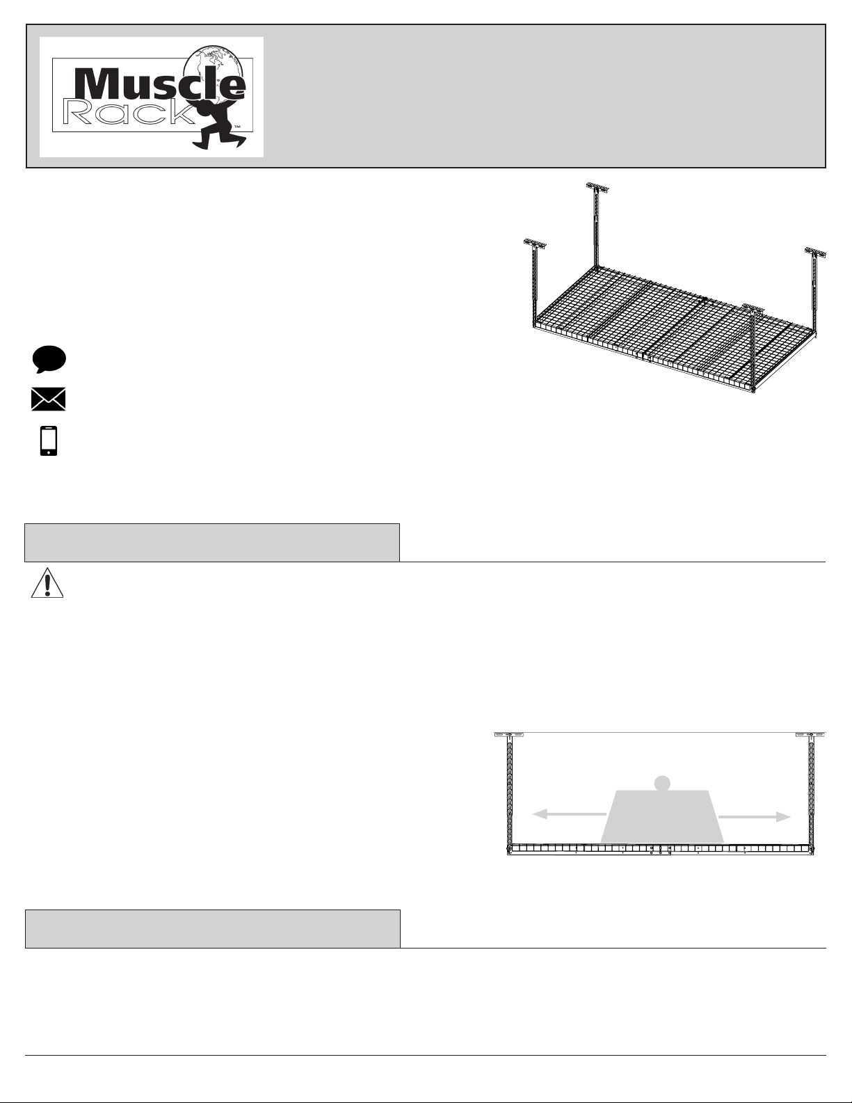
Adjustable Ceiling Storage Rack
Model # ACR4896B
WARNING: Excessive weight hazard! Use two or more people to move and install this rack to avoid injury.
Do not leave children unaended near overhead rack. High risk of injury if installed incorrectly. Follow instrucons
carefully and rounely inspect your system to ensure all components are fastened securely. DO NOT JUMP, CLIMB
OR HANG FROM THIS CEILING RACK. Never install more than one of these ceiling storage rack units on any two
overhead joist supports. Use care when working with metal parts, wear gloves. Do not use this unit for anything other
than the manufacture’s intended purpose.
600 lbs.
This unit has a total load capacity of 600 pounds of evenly
distributed weight (not to exceed 18.75 lbs. per square foot), using
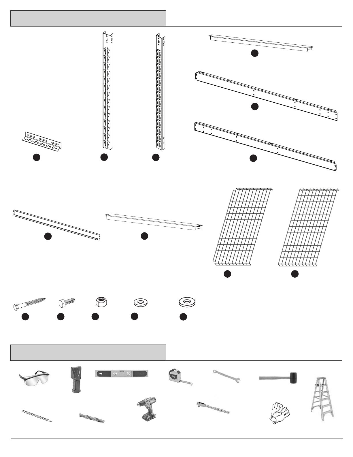
all 8 lag bolts (included in package) anchored into solid wood
joists or supports capable of supporng such a load. Do not over
load. Do not aempt to mount to steel beams. Be sure overhead
joists and supports are structurally sound. Edsal is not liable for
structure failure, or damage or injury resulng from structure
failure.
Warranty
Important Safety Informaon
USE AND CARE GUIDE
Quesons, problems, missing parts?
Contact our customer service department for assistance:
7 a.m. - 5 p.m., CST, Monday-Friday:
Chat: www.edsal.com/chat or www.edsal.com/contact
Phone: 1-773-475-3131
Edsal Manufacturing Company, Inc. products are guaranteed for a period of one (1) year from the date of purchase. The SOLE AND EXCLUSIVE REMEDY for
such defects is the repair or replacement of a defecve product or parts thereof by Edsal Manufacturing Company, Inc. or, at Edsal Manufacturing Company,
Inc opon, refund of the purchase price upon return of the item to Edsal Manufacturing Company, Inc.. This warranty shall not apply in the event the
products are damaged as a result of misuse, neglect, accident, moisture, improper applicaon, improper assembly, or assembly not in conformity with the
instrucons of Edsal Manufacturing Company, Inc., failure to abide by safety precauons prescribed by Edsal Manufacturing Company, Inc or modicaon
or repair by persons not authorized by Edsal Manufacturing Company, Inc..
To obtain replacement parts please provide: Model Number, Part Number & Descripon, Store Locaon and Date Purchased

2
A x4
Ceiling Angle
Bracket
#GLSA-B
Safety Glasses
Magnec Leveler
Tape Measure
Stud Finder
Pencil 7/32” Drill Bit
7/16” Open End
Wrench
Cordless
Power Drill
Rubber Mallet
Ladder
Tools Required
Parts List
Upper Post
#GLUP-B
B x4
Lower Post
#GLLR-B
C x4
Cross Support
#GLSTB-R-48-B
H x6
Center Support
#GLFTB-48-B
G x1
End Wire Deck
#GLWFDS-48
I x2
Center Wire Deck
#GLWFD-48
J x2
Le Beam
#GLBML-B
E x2
Right Beam
#GLBMR-B
F x2
Gloves
Side Brace
#GLSB-48-B
D x2
7/16” Socket Wrench
and
9/16” Socket Wrench
Lag Bolt
K x8
Hex Bolt
L x36
Lock Nut
M x36
Small Washer
N x72
Large Washer
O x8

Determine if your ceiling rack will be installed parallel or perpendicular to the direcon of your ceiling joists. Use a
stud nder to locate the joists if ceiling is nished with drywall.
Check the spacing of your ceiling joists to ensure that they will work for the size and direcon of your ceiling rack
install. If the spacing of your joists is 24” there should be ceiling joists located in the necessary posion. See note
below if spacing is an issue.*
3
*Note: If the spacing of your ceiling joists does not match the desired assembled size and direcon of your ceiling
rack installaon you will need to install an addional joist support in the correct posion (not included). See below
for suggested addional joist support soluons. If your unsure how to install addional joist supports, consult with
your local professional contractor for assistance.
Parallel Perpendicular
72" or 96"
For a parallel installaon ensure that the ceiling
joists are 48” apart.
For a perpendicular installaon ensure that the ceiling
joists are 72” or 96” apart depending on the ceiling
rack conguraon that best suits your needs.
Assembly Instrucons
48"
Step 1 - Plan the Installaon
Note: Measure from center to center
of ceiling joists using a tape measure.

4
Assembly Instrucons
Note: Install into solid wood joists only. Brackets must be mounted perfectly in line and square to each other.
Make sure the lag bolts are ght against the joist but DO NOT over-ghten the lag bolts. If they are over-
ghtened, the bolt could snap or the hole may be stripped.
Step 2 - Install Ceiling Brackets (A)
Locate and mark the center of ceiling joist with a pencil.
Use a stud nder to locate the joists if ceiling is nished
with drywall. Use Ceiling Angle Bracket as a template to
mark the two end holes of the Ceiling Angle Bracket on
the center line of the joist using a pencil. Drill pilot holes
using a 7/32” drill bit to the marked locaons.
✓
Depending on the ceiling rack size and orientaon
determined, measure 48, 72 or 96” from the installed
ceiling angle bracket to determine the locaon of the
second ceiling angle bracket along the same joist.
Must be measured from the same end of the bracket.
Repeat the steps to install the second ceiling angle
bracket in the same orientaon as the rst.
Install Ceiling Angle Bracket (A) into marked joist us-
ing two Lag Bolts (K) and two Large Washers (O) with a
9/16” socket wrench. The Lag Bolts should be installed
into the two end holes of the Ceiling Angle Brackets.
X
X
A
A
48”, 72” or 96”
For the second set of brackets, depending on desired
size and orientaon, measure 48”, 72” or 96” from
edge of installed ceiling angle bracket to the other
locaon for the next bracket on the other joist. The
bracket should be installed in the same orientaon and
must measure 48”, 72” or 96” from same edge of each
bracket. Repeat the steps to install the second set of
ceiling angle brackets in the same orientaon.
72”
96”
48”
Note: If spacing in joists do not match up to the desired
assembled size and direcon you will need to install an
addional joists to accommodate, see page 3 for opons.
Must measure 48”, 72” or 96” from same end of
each bracket.
Must measure 48”, 72” or 96” from same edge of
each bracket.

5
Assembly Instrucons
Step 3 - Assemble Upper and Lower Posts (B & C)
27 - 42”
C
B
✓
Note: Must be bolted at the highest
point and lowest point of the two
posts and at opposite holes.
Determine desired height of ceiling rack from the ceiling to boom of the overhead rack. Join the upper and lower
post and line up the holes to the determined height. Bolt Upper Post (B) to Lower Post (C) using two Hex Bolts (L),
two Lock Nuts (M) and four Small Washers (N). Bolt at the top hole locaon of the lower post and at the boom hole
locaon of the upper post where they overlap. Each bolt assembly should be on opposite holes. Repeat assembly
for the remaining three Upper Post (B) and Lower Post (C) at the same height.
For Parallel Assembly: Bolt one post assembly to the inside of the installed ceiling angle bracket through the center
hole using one Hex Bolt (L), one Lock Nut (M) and two Small Washers (N). The tapered ends of the post slots must
be facing down. Repeat Post assembly installaon to the Ceiling Angle Bracket located on the same joist in the same
manner and orientaon. For the other two remaining Post Assemblies, installaon will be on the outside of the
ceiling angle bracket. Bolt one each of the post assembly to the outside of the other two installed ceiling angle
brackets located on the other joist using one Hex Bolt (L), one Lock Nut (M) and two Small Washers (N) for each post
assembly. The tapered ends of the post slots must be facing down.
posts assembled to
the inside of bracket
posts assembled to
the outside of bracket
Post Assembly to the outside
of Ceiling Angle Bracket
tapered
ends
of post
slots face
down
Step 4 - Install Post Assemblies
C
B
✓✓
Post Assembly to the inside
of Ceiling Angle Bracket

6
Assembly Instrucons
Step 5 - Install Side Braces (D)
Line up the top and boom holes on the ends of the Side Brace (D) with the two holes located on the outer boom
sides of two post assemblies. Bolt each end of the side brace to the posts assemblies using two Hex Bolt (L), two
Lock Nut (M) and four Small Washers (N) through the top and boom holes of the side brace and the two holes of
the post. Repeat assembly for the other Side Brace (D) to the other set of post assemblies.
Note: The assembly of the
side braces must be on the
outside of the posts.
D
D✓
For Perpendicular Assembly: Bolt together one post assembly through the hole located on the side of the post to
the center hole of the inside angle of bracket using one Hex Bolt (L), one Lock Nut (M) and two Small Washers (N).
The backside of the post must be facing in and the tapered ends of the post slots must be facing down. Repeat post
assembly for the bracket located on the same joist, making sure backside of the post faces in and the tapered ends
of the post slots face down (as illustrated below). Repeat steps for other two post assemblies to the brackets on the
other joist.
Step 4 - Install Post Assemblies Connued
tapered end
of post slots
face down
✓
D

7
Assembly Instrucons
Step 7 - Install Beam Assemblies
Tap down lightly on beam with rubber
mallet to seat the beam clips into the
tapered ends of the slots.
Step 6 - Assemble Le and Right Beams (E & F)
72” Assembly
✓
✓
E
F
96” Assembly
E
F
✓
F
F
E
E
Bolt together one Le Beam (E) and one Right Beam (F) at the determined 72” or 96” length assembly by using four
Hex Bolts (L), four Lock Nuts (M) and eight Small Washers (N). Repeat steps to assemble the other Le and Right
Beam.
Install one beam assembly by aaching both ends of the beam into the boom slots of each post. Use a rubber
mallet to lightly tap down on each end of the beam to properly seat the beam clips into the tapered ends of the slot.
Bolt together by using one Hex Bolt (L), one Lock Nut (M) and two Small Washers (N) per side into the lined up holes
of the beam and post. Repeat step to install the other beam assembly to other posts assemblies.

8
Assembly Instrucons
Step 8 - Install Center Support (G)
72” Assembly View
96” Assembly View
Bolt the Center Support (G) into the two holes found in the middle of each beam assembly (see diagrams for
reference to hole locaon on a 72” or 96” beam assembly). Use two Hex Bolts (L), two Lock Nuts (M) and four Small
Washers (N) per side.
✓
G
G
G
G
✓

9
Assembly Instrucons
Step 10 - Install Wire Decking (I & J)
Only one Center Wire Deck (J) will be used
for a 72” ceiling rack installaon.
Step 9 - Install Cross Supports (H)
Assemble the six Cross Supports (H) by placing the rivets located on both ends of the cross support into the triangular holes
located on the top ledge of the both beam assemblies.
Two Center Wire Decks (J) will be used
for a 96” ceiling rack installaon.
Note: Be sure the notched
ends on the End Wire Deck (I)
are installed facing the posts.
96” Assembly View
72” Assembly View
I
I
J
J
J
H
H✓
I
Place the End Wire Decks (I) on the ends of the beams with the notched corners facing the end corners of the posts.
The notched corners should provide clearance for the posts. Place one Center Wire Deck (J) between the previously
installed end wire decks for a 72” ceiling rack, or install two for an 96” ceiling rack. There will be one center wire deck
le over if installing on a 72” wide ceiling rack.

Assembly Instrucons
10
Retain this manual for future use.
STEP 11 - Final Inspection
Check each beam and post connecon to be sure that the beams are properly seated and brackets are rmly
connected to the overhead joists. Make sure all bolts and nuts are properly ghtened. It is recommended to
periodically repeat this inspecon process to ensure safety.
✓
Table of contents
Other Muscle Rack Storage manuals
Popular Storage manuals by other brands

Teac
Teac HD3U-80 installation guide

Sony
Sony SDT-S9000 - DDS Tape Drive Operator's guide

RAIDAGE
RAIDAGE EAGE1040TG-SAU3 user manual

Medion
Medion External hard disk user guide

Fujitsu
Fujitsu MAX3036FC Product/maintenance manual

Western Digital
Western Digital WDH2U20000 - My Book Mirror Edition Hard Drive... Specifications

TwinMOS
TwinMOS USB 2.0 Mobile Disk Quick installation guide

G-Technology
G-Technology G DRIVE user manual

IBM
IBM SAN192C-6 Installation, service and user guide

HP
HP StorageWorks 1000 - Modular Smart Array Administrator's guide

HP
HP ProLiant SB460c - SAN Gateway Storage Server user guide

Seagate
Seagate SPINPOINT F3 HD164GJ Specifications