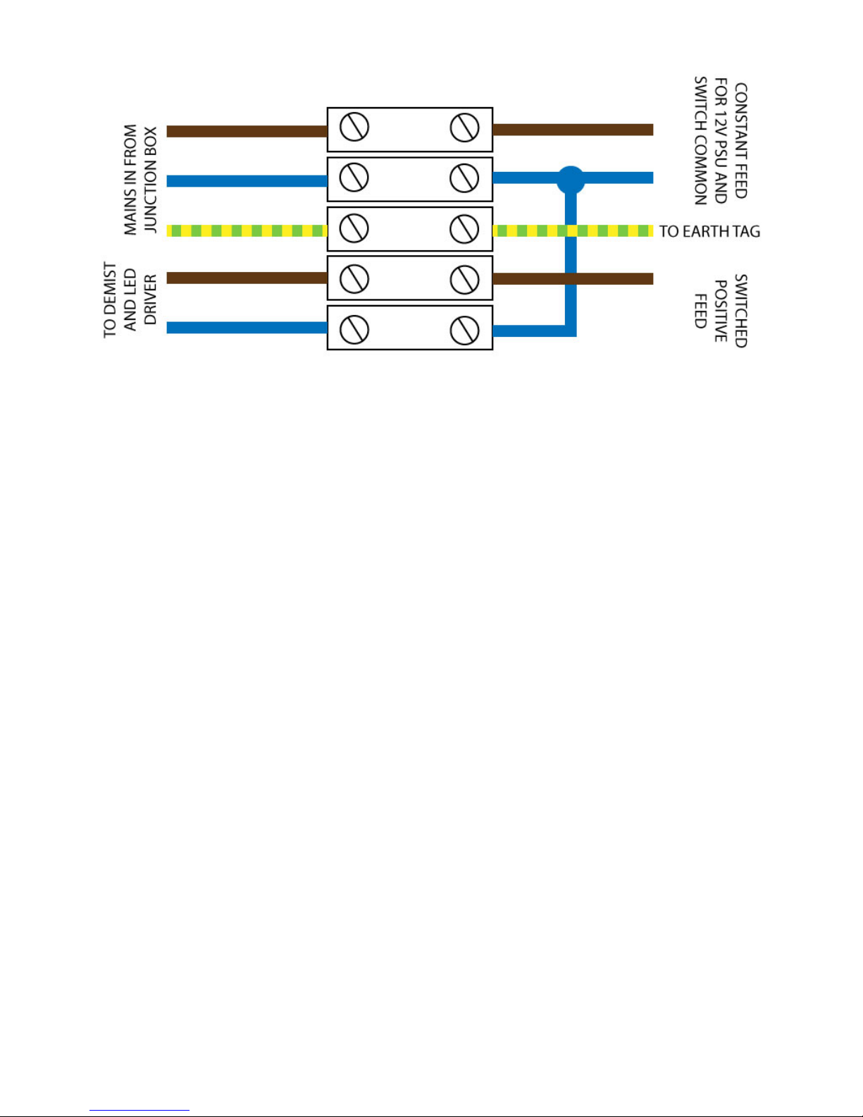
Music in Every Room Tenor Audio Mirror User manual

Music in Every Room Ltd
Tenor Audio Mirror
Bluetooth
FM/DAB Radio
What’s in the box:
1. Mirror with attached aerial
2. Remote control with tted battery
3. 4 x Fixing screws, raw plugs and 3
grommets
4. Fixing Template
5. Install and operation instructions
Please carefully inspect the mirror to en-
sure no damage has occured in transit. If
any damage is evident please photograph
both the mirror and any damage to the
packaging and contact us directly.
SAFETY
• THE MIRROR MUST BE INSTALLED BY A COMPETENT PERSON IN
ACCORDANCE WITH CURRENT IEEE REGULATIONS.
• IF IN DOUBT CONSULT A “PART P” REGISTERED ELECTRICIAN.
• THE MIRROR MUST BE PERMANENTLY INSTALLED AND NOT
CONNECTED TO A TRAILING PLUG/SOCKET.
• THE MIRROR MUST BE EARTHED.
• e product is for indoor use only in a ventilated bathroom. It is not
suitable for saunas, steam rooms or shower cubicles.
• e mirror is suitable for installation in Zone 2 and outside zones. It must
not be installed in Zone 0 or Zone 1. Please refer to the diagram.

1.Selecting the installed position
Do not install in Zone 0 or Zone 1, or a position where it can be accidentally sprayed down
with the shower head.
It will require a mains cable feed to the rear of the case. (see wiring section) and ideally a co-
axial feed for a remote aerial.
e mirror weighs 14kgs so ensure tting is to a sturdy wall.
Light proximity sensor
e base of the mirror should be 150mm clear of any under surface (sink, shelf etc.) to prevent
interference to the LED proximity switch.

Li the bottom edge of the glass and support as shown, resting the top brackets on the edge of
the case. Use a prop to hold the glass at an angle to make it easier to disconnect cables.
3. Remove glass from case
Lay the mirror case down at on a suitable surface and remove the 6 screws indicated by the
red arrows
2. Reception
e mirror has its own tted aerial which in strong signal areas will be adequate. Mounting
near a window generally improves reception.
For best performance we strongly recommend a coaxial feed is run to a full external DAB/FM
aerial, roof or lo mounted.

4. Position the mirror on the wall
A Template 800 x 600 mm is included, use this to determine best position and height.
Use a spirit level and stick the template to the wall in the exact position required.
Please Note: e template positions allow for the mirror to drop by 12mm when it is hung from
the keyhole slots, it will position exactly to the template.
Mark rough:
4 x Keyhole slots
Mains Cable
External aerial coax (if tted)
Once all cables have been disconnected li the glass clear of the case to a safe position
Take care to protect the edges of the glass, do not stand the mirror on its glass edge unless
protected by so material.
Disconnect: Low Voltage DC Plug - Black
2 x Speaker cables - Red
Aerial “F” Connector - Brown
LED Strip light connector - Red/Black
Earth Tag - -Green/Yellow

5. Wiring
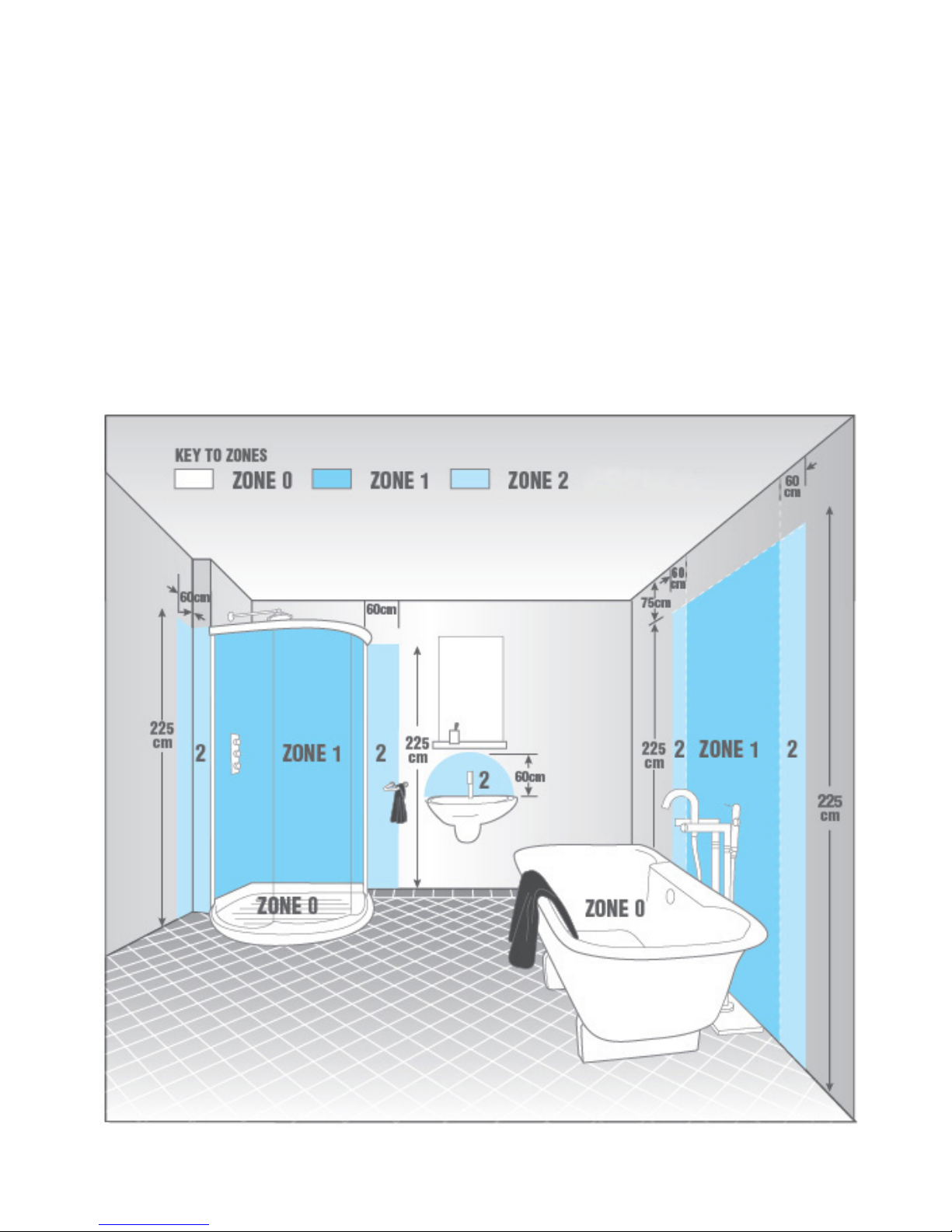
SAFETY - THE MIRROR MUST BE EARTHED
THE MIRROR MUST BE WIRED FROM AN RCD DEVICE
WE RECOMEND WIRING VIA A LOCAL FUSED SPUR FUSED AT 3 AMPS
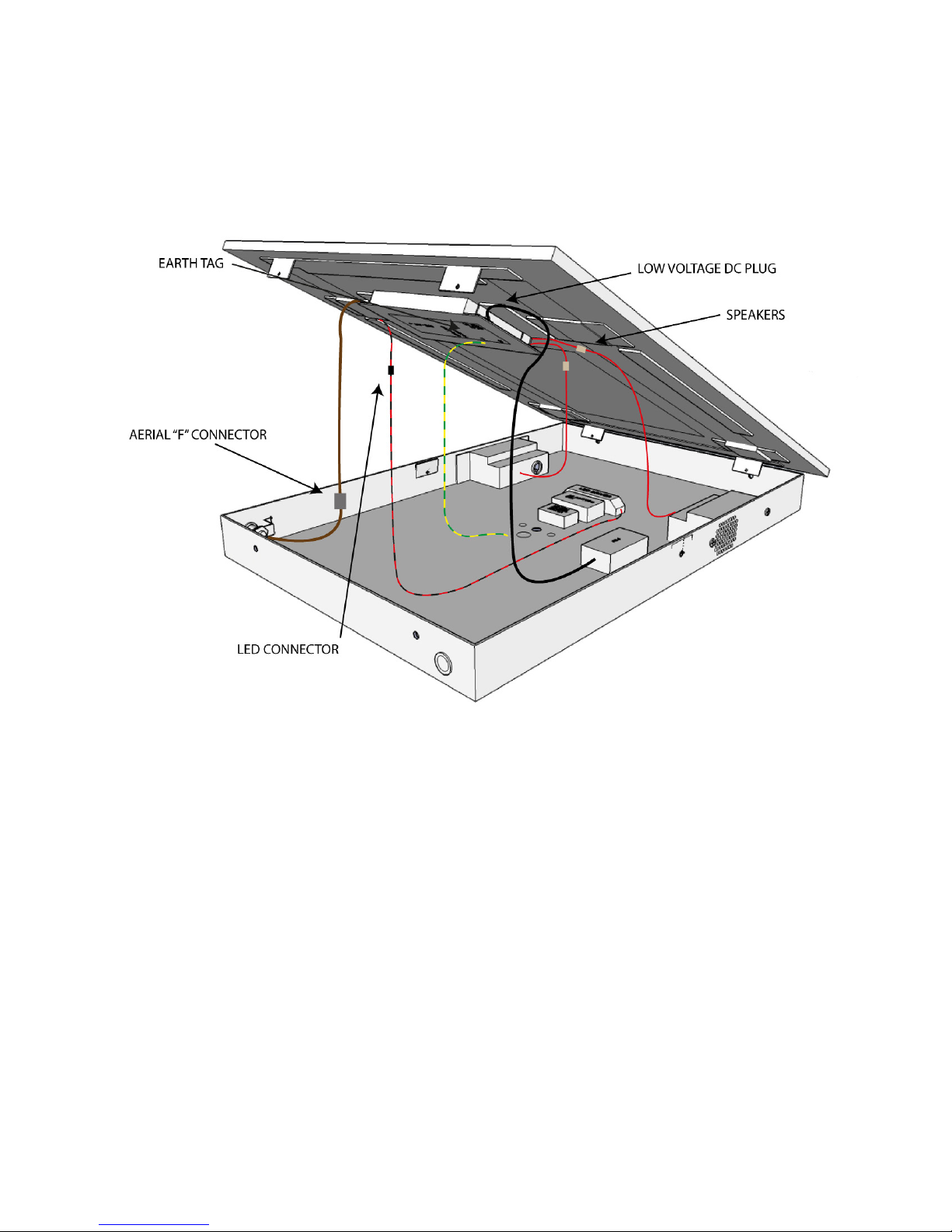
e mirror is supplied with a connected mains cable. e installing electrician may wish to make
use of this cable or to replace it with a pre installed cable. In the later case open the mains terminal
box, remove the provided cable and wire in the new cable.
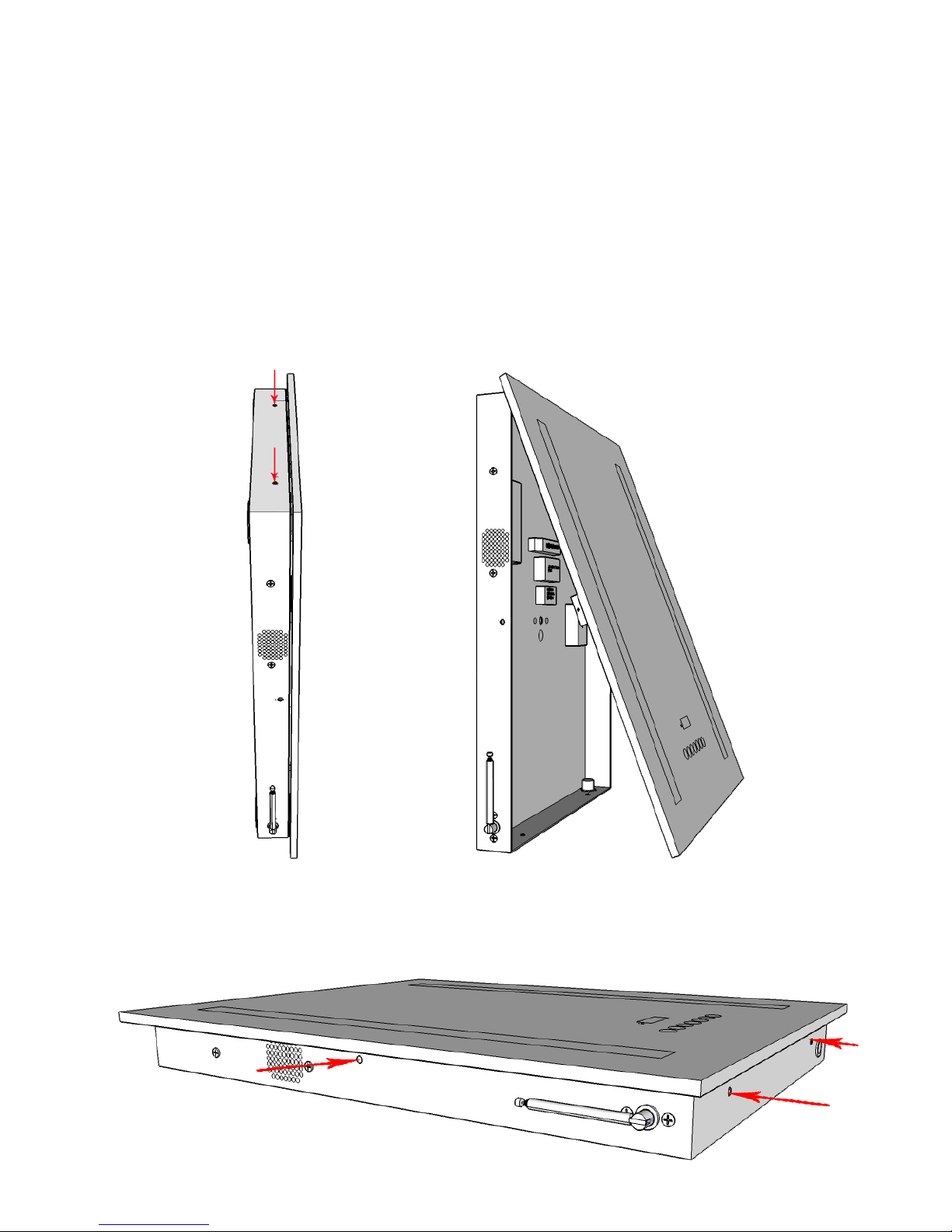
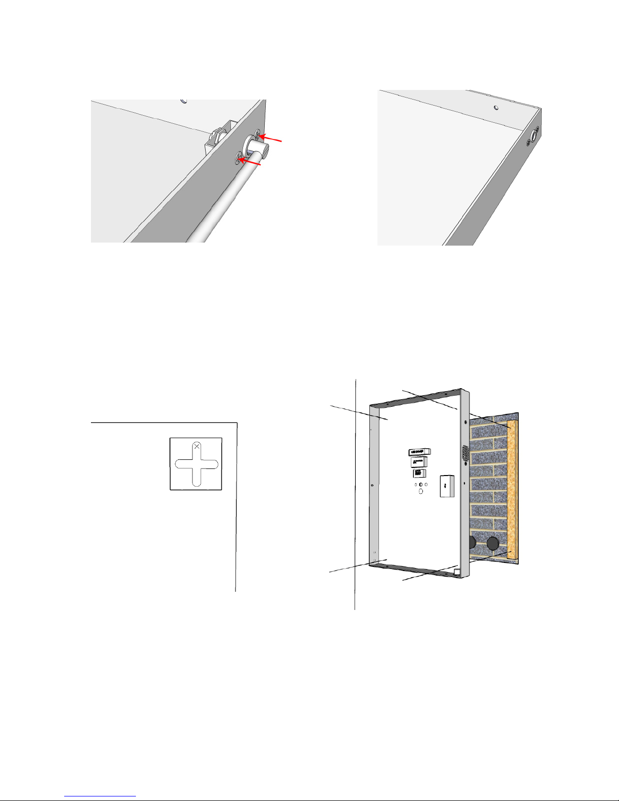
4 x Keyhole slots
Cable entry for mains feed and coaxial
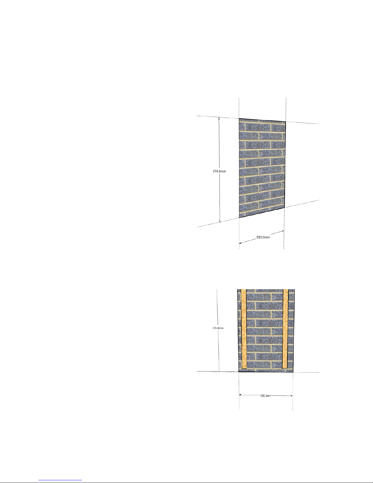
Drill the wall for rawl plugs, 4 x 8mm rawl plugs and
screws are provided but contractors must assess and pro-
vide xings appropriate for the wall-- Solid, Stud, Dot and
Dab, etc. e mirror weighs 14kg, make sure its secure.
When hung the mirror should be tight to the wall. Test the
screw height with the case. You may wish to add a retain-
ing baton along the top of the case to prevent it being
lied upwards o its hanging plates.
AERIAL
e mirror is tted with a side mounting aerial. In strong reception areas this may be adequate, but
for best radio performance ---
WE STRONGLY RECOMMEND YOU WIRE IN AN EXTERNAL FM/DAB AERIAL.
Mount the aerial externally or in the lo and wire to the mirror with coaxial cable.
Use the open grommet provided to bring the coaxial into the rear of the case. Terminate with an “F”
connector and connect in place of the side mount aerial. Unscrew the two small screws retaining the
side aerial bracket. e side mount aerial can now be removed through the hole and use the blank-
ing grommet removed from the rear of the case to ll the hole.
In a stud wall a terminal box can be tted inside
the cavity. is allows the case to be oered to the
wall and wired into the terminal box using the
supplied cable. An external aerial coax can also be
provided. As the mirror is oered to the wall the
connecting cables will hang down into the cavity.

6. Hanging the mirror
Hang the case securely to the wall and wire in the mains cable.
With the case wired and securely hung, oer up the glass and loosely t the two top screws as indicated
Swing the glass outwards always supporting the base and remake the connections.
Connect: Low Voltage DC Plug - Black
2 x Speaker cables - Red
Aerial “F” Connector - Brown
LED Strip light connector - Red/Black
Earth Tag - -Green/Yellow
Once all the connections have been made, close the glass to the case, align the screw holes and t the
other 4 screws, As you tighten press lightly on the glass to compress the gasket.

FULLY RECESSING THE MIRROR
It’s possible to fully recess the mirror. It will then operate:
• Wired to on-wall or ceiling speakers
• Wired to an external FM/DAB aerial
• Rewire the LED to the room, or a separate light switch
1.Installation
Cut a hole in the wall 774mm high 535mm wide.
e case is 762mm in height. It enters the top of the
cut out and drops 12mm onto the keyslots
Recess depth
Within the recess x 2 vertical batons (aprox
20mm deep) that will hold the xing screws and al-
low room for spare cable as the mirror is hung back
into position. e case is 70mm deep from face to
keyhole slot (including the gasket). e case should
sit proud of the recess by 2-3mm. If you wish to tile
up to the mirror or silicon seal in the wall then set
at the appropriate clearance.
*Note - ONLY USE MIRROR/GLASS SEALANT,
STANDARD SILICON WILL DAMAGE THE
BACKING ON THE GLASS.

Split the glass fropm the case as previously described.
Remove the side mounting aerial by removing the screws shown, push the aerial back through the
hole to remove, ret the screws and t the blanking grommet tted in the rear of the case.
2. Fitting the case into the recess
Drill through the case keyhole slot in the position shown “X” below. Drill all 4 plates (approx 2mm)
is position should be the centre of the screw when engaged in the keyhole slot.
Place the case in the recess, resting on the lower edge of the cutout. Pack up the bottom of the case
by 4mm for clearance. Accurately mark through the drilled holes onto the batons. Remove the case
and x the mounting screws in the batons. Test that the case enters the cut out and drops down onto
the screws. It should be clear at the base and held securely to the wall. e gasket should t snugly
into the recess.
3. Wiring
Mains: Fit a mains connection block between the wall batons. Retain the mains cable supplied with
the mirror and cut to appropriate length (aprox 1m)
LED & Demist: e on/o proximity sensor will not be used. e LED/Demist on/o is rewired
through a separate switch. is could be next to the room light switch or alternatively a pull cord near
the mirror. Disconnect the LED sensor box (no longer used) from the incoming mains box and wire
the new switch. See diag over. Leave trailing wire of aprox 1m from the rear of the case. e cable
exists through one of the rear holes, gromet supplied. Fit a terminal box between the battons wired to
the external switch.

Speakers
Disconnect the inbuilt speakers and rewire to the rear of the case for ceiling or wall speakers. Leave aprox
1m of cable exiting from one of the rear holes, gromet supplied. Wire to terminal blocks positioned
between the batons.
We can oer an excellent range of appropriate speakers.
Aerial
Using an F connector run aprox 1 m of coaxial cable to the rear of the case and terminate with F connec-
tor. Wire coaxial to an external or lo mounted DAB/FM aerial.
Rear wiring connection
Reassemble the case and glass as previously described
Stand the assembled mirror within the cable length (aprox 1m) of the wall recess. Support and connect:
Mains into termination block
LED light/heater switch into termination block
Speakers into terminal block
Aerial into F connector
Li mirror and glass into the recess, push back and drop onto the 4 hanging screws. Conrm all 4 screws
engage securely.
You may wish to place beading across the gap at the top of the mirror case to prevent the mirror being
lied o its hangers.
4. Auxiliary audio input
e mirror has an auxiliary audio input, ideal for wiring in a bathroom TV or linking to a whole house
system.
Wire from the 3mm Auxiliary input maked on the control board using screen audio line cable.

Table of contents