Mustek PP4000 Series User manual

Rev.: Original
PP4000 Series
Thermal Printer
User's Guide

Federal Communications Commission Radio Frequency
Interference Statement
This equipment has been tested and found to comply with the limits for a Class A digital device,
pursuant to Part 15 of the FCC Rules. These limits are designed to provide reasonable protection against
harmful interference when the equipment is operated in a commercial environment. This equipment
generates, uses, and can radiate radio frequency energy and, if not installed and used in accordance with
the instruction manual, may cause harmful interference to radio communications. Operation of this
equipment in a residential area is likely to cause harmful interference in which case the user will be
required to correct the interference at his own expense.
For compliance with Federal Noise Interference Standard, this equipment requires a shielded cable.
This statement will be applied only for the printers marketed in U.S.A.
CE manufacturer’s Declaration of Conformity
(EC Council Directive 89/336/EEC of 3 May 1989)
This product has been designed and manufactured in accordance with the International Standards
EN50081-1/01.92 and EN50082-1/01.92 following the provisions of the Electro Magnetic
Compatibility Directive of the European Communities as of May 1989
Warranty Limits
Warranty will terminate automatically when the machine is opened by any person other than
the authorized technicians. The user should consult his/her dealer for the problem happened. Warranty
voids if the user does not follow the instructions in application of this merchandise. The manufacturer is
by no means responsible for any damage or hazard caused by improper application.
About This Manual
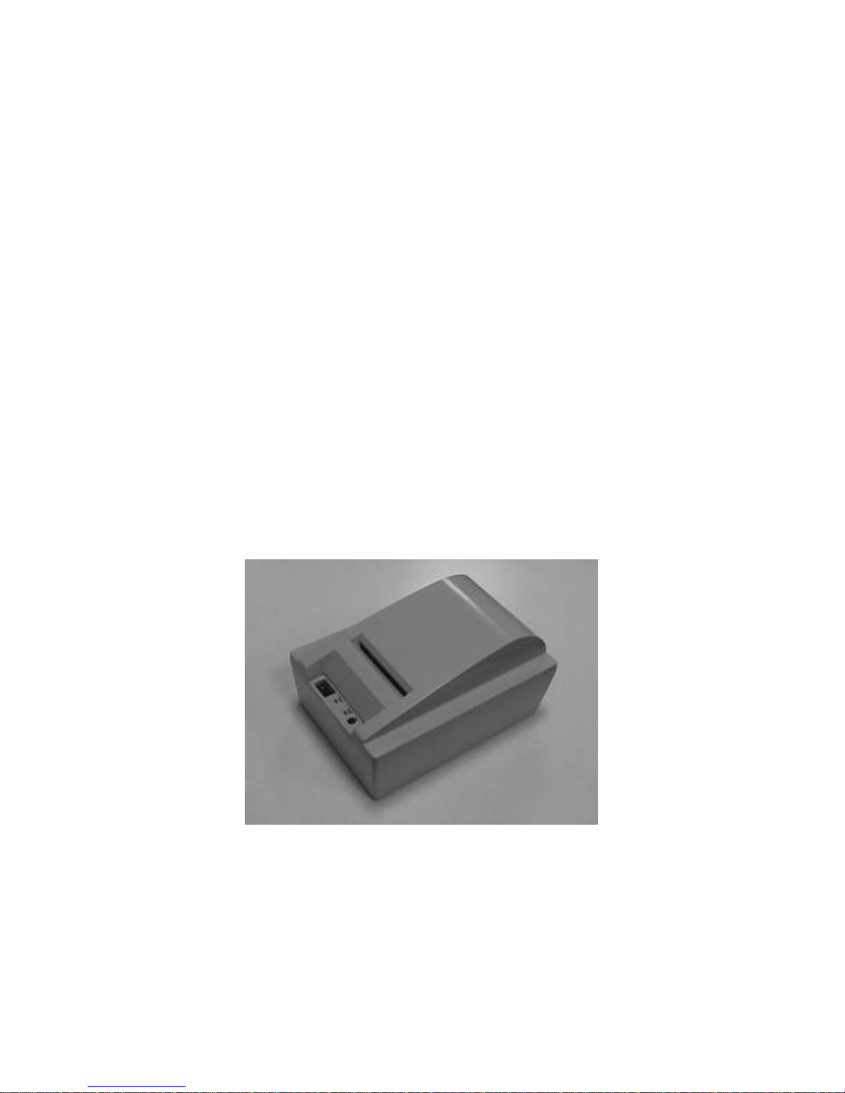
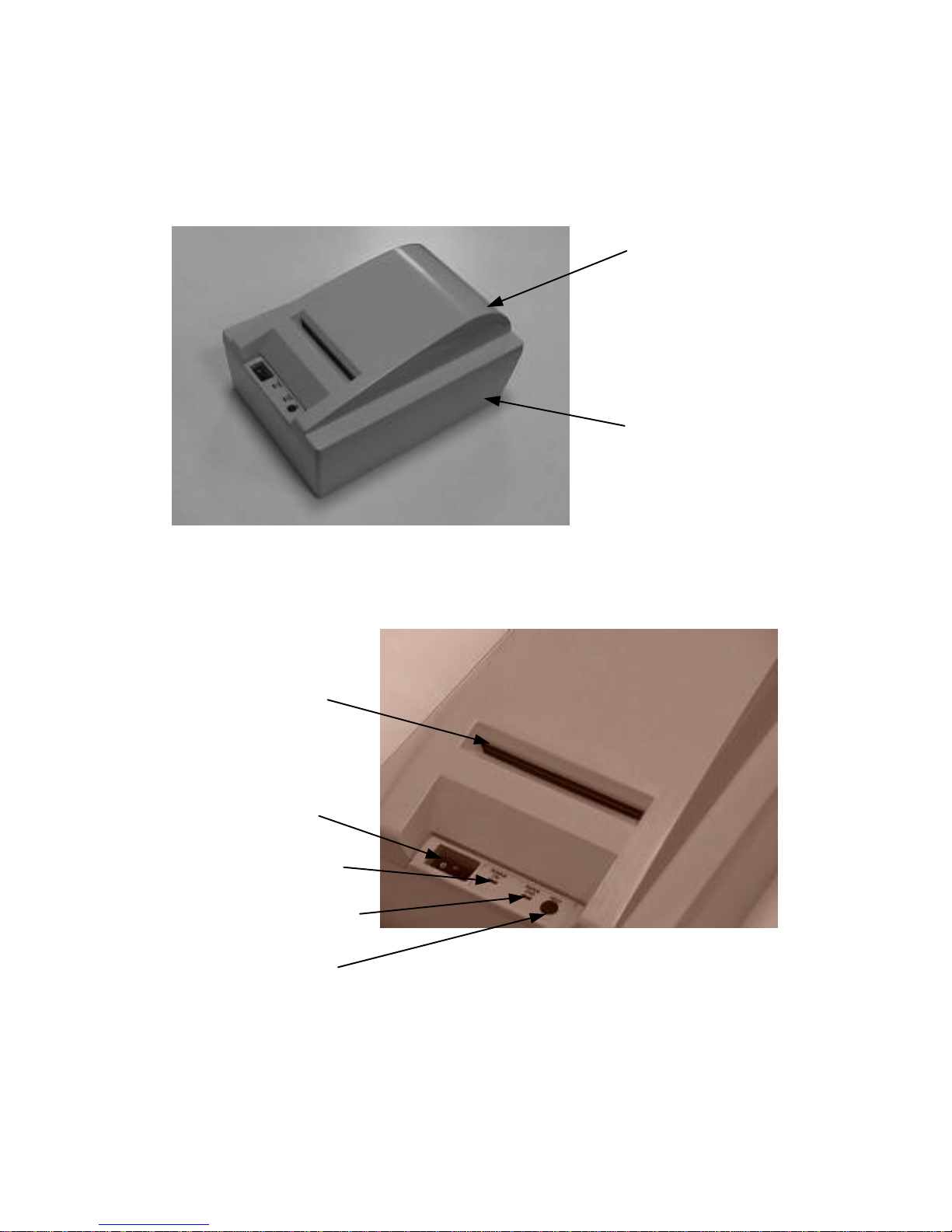
This manual is aimed to assist the user to utilize the PP4000 series which is a series of POS
thermal printers delicately designed to work with either serial or parallel interface connection. This
manual covers both operational and technical aspects. This manual is revised to cover also the Epson
emulation commands and some frequently asked questions.
The manufacturer of the PP4000 series heartily apologizes to the user for reserving the right to
change or to modify this manual without notice due to the rapid and constant progress and improvement
on science and technology. The user may always obtain the most up to date information through our
web site: http://www.posiflex.com.tw .
©Copyright Mustek Corp. 1998
All rights are strictly reserved. No part of this documentation may be reproduced, stored in a
retrieval system, or transmitted in any form or by any means, electronic, mechanical, photocopying, or
otherwise, without the prior written consent of Mustek Corp. the publisher of this documentation.

i
Table Of Contents
GETTING STARTED . . . . . . . . . . . . . . . . . . . . . 1-- 1
CONGRATULATION . . . . . . . . . . . . . . . . . . . . . 1-- 1
PRODUCT BRIEFING . . . . . . . . . . . . . . . . . . . . . 1-- 2
MODEL NUMBERS . . . . . . . . . . . . . . . . . . . . . . . 1 -- 3
UNPACKING . . . . . . . . . . . . . . . . . . . . . . . . . . . . . 1 -- 4
MAIN PARTS ON THE EXTERIOR . . . . . . . . . 1-- 5
INDICATORS . . . . . . . . . . . . . . . . . . . . . . . . . . . . 1-- 6
OPERATING ENVIRONMENT . . . . . . . . . . . . . 1 -- 7
USEFUL TIPS . . . . . . . . . . . . . . . . . . . . . . . . . . . . 1-- 8
QUICK START-UP . . . . . . . . . . . . . . . . . . . . . . . .2-- 1
LOADING PAPER . . . . . . . . . . . . . . . . . . . . . . . . 2-- 1
AUTO PAPER FEED . . . . . . . . . . . . . . . . . 2-- 2
MANUAL PAPER FEED . . . . . . . . . . . . . . 2-- 3
WHEN TO REPLACE PAPER . . . . . . . . . 2 -- 3
CONNECTING CABLES . . . . . . . . . . . . . . . . . . 2 -- 4
SERIAL CONNECTION . . . . . . . . . . . . . . 2-- 4
PARALLEL CONNECTION . . . . . . . . . . . 2 -- 5
PERIPHERAL CONNECTION . . . . . . . . . 2 -- 5
POWER CONNECTION . . . . . . . . . . . . . . 2-- 6
POWER ON . . . . . . . . . . . . . . . . . . . . . . . . . 2 -- 6
SELF TEST . . . . . . . . . . . . . . . . . . . . . . . . . . 2-- 7
MAINTENANCE AND INTERNAL PARTS . . . . 3 -- 1
MAINTENANCE GUIDE LINES . . . . . . . . . . . . 3-- 1
INTERNAL PARTS . . . . . . . . . . . . . . . . . . . . . . . 3-- 1
PAPER JAM . . . . . . . . . . . . . . . . . . . . . . . . . . . . . 3 -- 2
PRINT HEAD CLEANING . . . . . . . . . . . . . . . . . 3-- 2
SPECIFICATIONS . . . . . . . . . . . . . . . . . . . . . . . . . . . 4 -- 1
PRINTER . . . . . . . . . . . . . . . . . . . . . . . . . . . . . . . . 4-- 1
PAPER . . . . . . . . . . . . . . . . . . . . . . . . . . . . . . . . . . 4 -- 1

ii
POWER ADAPTOR . . . . . . . . . . . . . . . . . . . . . . . 4 -- 2
TECHNICAL INFORMATION . . . . . . . . . . . . . . . 5 -- 1
INTERFACES . . . . . . . . . . . . . . . . . . . . . . . . . . . . 5-- 1
SERIAL INTERFACE . . . . . . . . . . . . . . . . 5-- 1
RS232 . . . . . . . . . . . . . . . . . . . . . . . . . . 5-- 1
RS422 . . . . . . . . . . . . . . . . . . . . . . . . . . 5-- 1
PARALLEL INTERFACE . . . . . . . . . . . . . 5 -- 2
PERIPHERAL INTERFACE . . . . . . . . . . . 5 -- 2
HARDWARE SETTINGS . . . . . . . . . . . . . . . . . . 5 -- 3
SOFTWARE COMMANDS . . . . . . . . . . . . . . . . . 5-- 5
CHARACTER CODE PAGES . . . . . . . . . . . . . . . . . 6-- 1
PAGE 0 ENGLISH / JAPANESE . . . . . . . . . . . . 6-- 1
PAGE 1 ENGLISH / EUROPEAN . . . . . . . . . . . 6 -- 2

1 - 1
I. GETTING STARTED
A. CONGRATULATION
You have made a very wise decision by purchasing the high
speed –low noise –high resolution –light weight –high
reliability thermal printer PP4000 series of Posiflex products. This
series of printers has been elegantly designed for a Point-Of-Sale
application. The manufacturer of this printer not only wishes to
take this opportunity to congratulate your smart investment on
buying this printer but also likes to express the wishes for your
prosperous future by using it.

1 - 2
B. PRODUCT BRIEFING
The PP4000 series printer uses thermal sensitive paper in
form of a roll at a width of 80 mm. The PP4000 printer serves the
stand-alone POS application as well as the application within a
PST system equally perfect.
The PP4000 series can support different interface input
through different sub-codes to the model number. The interfaces
include RS232 for serial interface and Centronics for parallel
interface. PP4000 printer of different model number sub-codes
utilizes different connector, accessory cable and part of internal
circuitry to accommodate the requirement of different interface.
As a variation from the RS232 for serial interface, RS422 serial
interface is also available.
In addition to the capability of supporting international
character sets, there are also some models in PP4000 series that
supports the oriental characters as indicated in the following
paragraph about model numbers.
The PP4000 supports an auto cutter. The PP4000 also
supports application in different countries of various kinds of
power systems by changing the power adaptor and/or the power
cord to the power adaptor. The PP4000 further supports some
built-in bar code printing commands for UPC-A, EAN8, EAN13,
CODE 39, ITF and CODABAR.

1 - 3
C. MODEL NUMBERS
EXAMPLE: PP 4 00 0 S0
Power adaptor:
0: No adaptor
1: USA adaptor
2: European adaptor
3: UK adaptor
4: SA adaptor
5: AUS adaptor
Interface:
B: serial (RS422)
C: parallel
S: serial (RS232)
Reserved
Language/Expanded character set
0: English (standard)
1: GB-code Chinese
2: BIG-5 code Chinese
3: Korean
4: Thai
5. Japanese Kanzi
Reserved
Product series
4: thermal printer
POS printer
The last two digits in the model number structure as
explained above are called sub-codes. The rest are the basic
model number.

1 - 4
D. UNPACKING
As illustrated in the above picture, followings are items you
may find when you carefully unpack the carton that delivers
PP4000 series printer. If there is any discrepancy or problem,
contact your dealer immediately. Be sure to save the packing
materials in the event that the printer needs to be shipped at
some point in the future.
•The printer itself. Choices are PP4000S, PP4000C and
PP4000B.
‚Thermal paper roll. 80 mm wide, outer diameter 83 mm max.
ƒaSerial cable with 9 pin D sub Female to 9 pin D sub Male
connectors for PP4000S
ƒbParallel cable with 25 pin D sub Male to 25 pin D sub
Female connectors for PP4000C
„Power adaptor. (depends on sub-code ordered)
…Power cord for power adaptor (depends on sub-code ordered)
†This User’s Manual
•
‚
ƒaƒb
„
…
†

1 - 5
E. MAIN PARTS ON THE EXTERIOR
Power LED (green)
Paper End LED (red)
Paper feed button
Power On / off switch
Paper exit slot
Bottom base
Top cover

1 - 6
F. INDICATORS
•POWER LED: green
•PAPER END INDICATOR: red. Different lighting
pattern indicates each error status.
Lighting pattern Meaning
Constant light up Paper End
Constant blinking Paper Near End
1 blink plus OFF 1.2 seconds ABMARK
2 blinks plus OFF 1.2 seconds HEAD UP
3 blinks plus OFF 1.2 seconds TEMPERR
4 blinks plus OFF 1.2 seconds VOLTERR
5 blinks plus OFF 1.2 seconds HWRERR
Parallel connector
Serial connector
Power connectorPeripheral connector
Bottom plate

1 - 7
G. OPERATING ENVIRONMENT
•Place the printer on a sturdy, level surface.
•Choose a place that is well ventilated and free of
excessive dust, smoke or fume.
•Do not put the printer in direct sunlight or near a heater.
•Ideal room temperature is from 5ºC to 40ºC. Ideal
humidity is from 20% to 85% RH (no condensation).
•Since the paper roll is very thermal sensitive, please
keep them in a dark place that is 20º and 65% RH when
not installed in the printer.
•Use a grounded AC power outlet.
•Use only the power cord and power adaptor furnished
with the printer.
•Do not use a power outlet of a circuit shared with any
equipment that causes great electrical noise, such as
motors.
•Do not use a power outlet of a circuit shared with any
equipment that uses a lot of power, such as a copier or a
coffee maker.
•Do not touch any connector contacts to avoid possible
electrostatic damage.

1 - 8
H. USEFUL TIPS
•Do not pull the paper in the direction opposite to the
paper feeding direction with the print head closed.
•Do not touch the areas around the print head and motor
during or right after printing. It can be very hot.
•Do not use thermal paper containing Sodium (Na+),
Potassium (K+) and Chlorine (Cl-) ions that can harm
the print head thermal elements.
•Use only water paste, starch paste, polyvinyl paste or
CMC paste when gluing thermal paper.
•Use of volatile organic solvents such as alcohol, ester
and ketone on thermal paper can cause discoloration.
•Some adhesive tapes on thermal paper may cause
discoloration or faded printing.
•Use only products made from polyethylene,
polypropylene or polyester for storage of thermal paper.
If thermal paper touches anything includes phthalic acid
ester plasticizer for a long time, the image formation
ability may be reduced or the printed image may fade.
•If thermal paper touches diazzo copy paper immediately
after copying, the printed surface may be discolored.
•Thermal paper must not be stored with the printed
surfaces against each other as the printing may be
transferred between the surfaces.
•If the surface of thermal paper is scratched with a hard
metal object such as a nail, the paper may become
discolored.

1 - 9
•Store thermal paper away from high temperature and
humidity. Avoid extended exposure to direct light.
•Do not set any liquid or drinks such as coffee on the
printer case

2 - 1
II. QUICK START-UP
A. LOADING PAPER
Open top cover by gently pressing the rear part of cover
inward and lift it up. Take the cover away to expose the paper roll
compartment and the thermal print engine.
Put the paper roll into the paper roll compartment in the
direction shown as above. Push down the head-up lever on
Paper roll compartment
Thermal print engine
Head-up lever Rear insert slotNote direction of paper roll

2 - 2
thermal print engine and try to aim the front end of the paper roll
toward the rear insert slot.
When the front end is inserted into the rear insert slot, close
up the head-up lever and turn the paper feed knob to roll the paper
forward. If the paper is not inserted in proper position, you may
push down the head-up lever and adjust the position of paper and
close up the head-up lever again.
1. Auto paper feed
This printer automatically feeds paper forward about 4 mm
every time it is powered up or every time the head-up lever is
closed up during power on. Therefore, you may tear the front end
of paper roll off against the auto cutter assembly. You may then
put on the top cover back and have the new front end of paper
come out to the paper exit slot automatically when the printer is
powered on.
Paper feed knob
Tear paper off

2 - 3
2. Manual paper feed
You may also extend the front end of paper out of the paper
exit slot of the top cover and put top cover back to the printer case.
Tear the paper off or cut the paper by software command later.
3. When to replace paper
Whenever the printer gives paper near end signal or a red
line appears on the thermal paper, it is the proper timing for
replacing the paper. Do not wait till the print engine is dragging
the paper roll at the very end. Remove the leftover and replace a
new paper roll as illustrated above to prevent excessive paper dust
in the printer and consequently possibility for paper jam.
Front end of paper Front end of paper

2 - 4
B. CONNECTING CABLES
1. SERIAL CONNECTION
All the external connectors are in the recessed area at the
rear bottom. The serial connector is a 9 pin D sub Female
connector at the left. Apply this cable only for serial application
of the serial model. The protocol used in serial connection is
always 19200 bps, none parity, 8 data bits, 1 stop bit.
All connectors are at the
bottom rear
This cable comes from any
COM port of host computer

2 - 5
2. PARALLEL CONNECTION
The parallel connector is a 25 pin D sub Male connector at
the rightmost location in the connector area. Apply this cable only
for parallel model.
3. PERIPHERAL CONNECTION
The peripheral controller is a RJ11 jack near the serial
connector. With use of Posiflex special split cable (CCBLA-238
as an option) for cash drawer control, this port can control two
cash drawers.
This cable
connects to
LPT port
of the host
computer
This cable
goes to cash
drawer.

2 - 6
4. POWER CONNECTION
The power connector is a 3 pin jack between the peripheral
connector and the parallel connector. During insertion, be sure to
hear the click to obtain a firm contact.
CAUTION: Before doing the insertion or extraction of the
power plug, be sure to pull the outer sleeve of the
plug backward to release the internal latch.
Failure to do this could damage the power plug.
Such damage is considered as an artificial
destruction and is not covered by the warranty.
5. POWER ON
When all the above cable connections are made correctly,
you may connect your power adaptor to the wall outlet. Make
sure that the type of power cord and the voltage requirement of
the power adaptor meet the local power conditions. Now the
printer is ready for power on.
Power connector from power adaptor
Pull back the
outer sleeve first

2 - 7
6. SELF TEST
Press and hold down the paper feed button while turning the
on / off switch on. The printer will then perform a self test. A slip
of self test result is printed below. Please note that the content of
such print is always the same no matter what interface or
communication protocol is used.
Please note that there could be some mild vibration of the
printer due to intermittent pulling on the paper roll by the motor.
This vibration would be lighter with thinner paper roll and higher
printing speed and heavier with thicker paper roll and lower
printing speed.
Paper feed button
On / off switch
Table of contents