variations and HARMONICS controls the frequency spread or the balance between the various
constituents of the tone.
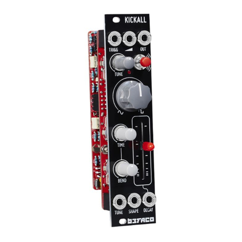
F. Attenuverters for the TIMBRE, FM and MORPH CV inputs. When the corresponding CV input is left
unpatched and the trigger input [3] is patched, the attenuverter adjusts the modulation amount from the
internal decaying envelope generator. When unplugging a CV input, and if the trigger input is patched,
remember to reset the attenuverter to 12 o’clock if you do not want the internal envelope to take over!
Inputs and outputs
1. Model selection CV input. When this CV input is modulated, two LEDs are lit: the steadily lit LED
indicates the current model, and the slowly blinking LED indicates the central value, which would be
obtained with a CV of 0V and which is still modifiable with the buttons [A].
Note that when the trigger input [3] is patched, model changes occur only whenever a trigger is received.
2. CV inputs for the timbre, frequency, morph and harmonics parameters.
3. Trigger input. Serves four percussive purposes:
Triggers the internal decaying envelope generator.
Excites the physical and percussive models.
Strikes the internal low-pass gate (unless the LEVEL CV input [4] is patched).
Samples and holds the value of the MODEL CV input.
4. Level CV input. Opens the internal low-pass gate, to simultaneously control the amplitude and
brightness of the output signal. Also acts as an accent control when triggering the physical or percussive
models.
5. V/Oct CV input. Controls the fundamental frequency of the sound, from -3 to +7 octaves relative to the
root note set by the coarse frequency knob [B].
6. 7. Outputs. The AUX output carries a variant, sidekick, or by-product of the main signal produced on
OUT.
SETTINGS
Adjusting the internal LPG and envelope
Hold the first button (A) and:
Turn the TIMBRE knob to adjust the response of the LPG, from VCFA to VCA.
Turn the MORPH knob to adjust the ringing time of the LPG and the decay time of the internal envelope.
The value of both settings are represented by 4 yellow LEDs.
Adjusting the FREQUENCY knob range
Hold the second button (A) and turn the HARMONICS knob to adjust the range of the FREQUENCY knob.
The first 8 settings correspond to C0 +/- 7 semitones, C1 +/- 7 semitones, and so on. The last setting, with
all LEDs lit, corresponds to the full 8-octave range from C0 to C8.
