Mutec FORMAT CHANGER advanced User manual

�������������������������������������������������������
�
���������������������������������������������������������������������


WARRANTY REGULATIONS
§1 Warranty
MUTEC GmbH warrants the flawless performance of this product to the original buyer for a period of two (2) years from the date of purchase. If any failure occurs within
the specified warranty period that is caused by defects in material and/or workmanship, MUTEC GmbH shall either repair or replace the product free of charge within 90
days. The purchaser is not entitled to claim an inspection of the device free of charge during the warranty period. If the warranty claim proves to be justified, the product
will be returned freight prepaid by MUTEC GmbH within Germany. Outside Germany, the product will be returned with the additional international freight charges payable
by the customer. Warranty claims other than those indicated above are expressly excluded.
§2 Warranty transferability
This warranty is extended exclusively to the original buyer who bought the product from a MUTEC GmbH specialized dealer or distributor, and is not transferable to anyone
who may subsequently purchase this product. No other person (retail dealer, distributor, etc.) shall be entitled to give any warranty promise on behalf of MUTEC GmbH.
§3 Waranty regulations
The return of the completed registration card, or online registration on one of the websites specified below, is a condition of warranty. Failing to register the device before
returning it for repair will void the extended warranty.
The serial number on the returned device must match the one stated on the registration card or entered during online registration. Otherwise, the device will be
returned to the sender at the senders expense.
Any returned device must be accompanied by a detailed error description and a copy of the original sales receipt issued by a MUTEC dealer or distributor.
The device must be returned free of shipping expenses and in the original package, if possible; otherwise, the sender has to provide comparably protective packaging.
The sender is fully responsible for any damage or loss of the product when shipping it to MUTEC GmbH.
§4 Limitation of warranty
Damages caused by the following conditions are not covered by this warranty:
Damages caused by every kind of normal wear and tear (e.g. displays, LEDs, potentiometers, faders, switches, buttons, connecting elements, printed labels, cover
glasses, cover prints, and similar parts).
Functional failure of the product caused by improper installation (please observe CMOS components handling instructions!), neglect or misuse of the product, e.g.
failure to operate the unit in compliance with the instructions given in the user or service manuals.
Damage caused by any form of external mechanical impact or modification.
Damage caused by the users failure to connect and operate the unit in compliance with local safety regulations.
Damage caused by force majeure (fire, explosion, flood, lightning, war, vandalism, etc.).
Consequential damages or defects in products from other manufacturers as well as any costs resulting from a loss of production.
Repairs carried out by personnel which is not authorized from MUTEC GmbH will void the warranty. Adaptations and modifications to the device made with regard to
national, technical, or safety regulations in a country or of the customer do not constitute a warranty claim and should be set with MUTEC GmbH in advance.
§5 Repairs
To obtain warranty service, the buyer must call or write to MUTEC GmbH before returning the unit. All inquiries must be accompanied by a description of the problem and
the original buyers invoice. Devices shipped to MUTEC GmbH for repair without prior notice will be returned to the sender at the senders expense. In case of a functional
failure please contact:
MUTEC Gesellschaft fuer Systementwicklung und Komponentenvertrieb mbH
Siekeweg 6/8 12309 Berlin Fon 030-746880-0 Fax 030-746880-99 [email protected]
MUTEC GmbH assumes no liability for any incorrect information given in this manual. Please note that
all software/hardware product names are registered trademarks of their respective owners. No part of
this manual may be reproduced, copied or converted to a machine-readable form or electronical media
without a written permission of MUTEC GmbH. We reserve the right to change or improve our products
without notice. © MUTEC GmbH 2002
SAFETY INSTRUCTIONS
General instructions
To reduce the risk of fire or electrical shock, do not expose this appliance to rain or moisture, direct
sunlight or excessive heat from sources such as radiators or spotlights. No user serviceable parts are in-
side. Repair and maintenance must be carried out by qualified personnel authorized by MUTEC GmbH!
The unit has been designed for operation in a standard domestic environment. Do NOT expose the unit
and its accessories to rain, moisture, direct sunlight or excessive heat produced by such heat sources as
radiators or spotlights! The free flow of air inside and around the unit must always be ensured.
Initial operation
Prior to the initial operation of the unit, the appliance, its accessories and packaging must be inspected
for any signs of physical damage that may have occurred during transit. If the unit has been damaged
mechanically or if liquids have been spilled inside the enclosure, the appliance may not be connected
to the mains or must be disconnected from the mains immediately! If the unit is damaged, please do
NOT return it to MUTEC GmbH, but notify your dealer and the shipping company immediately, other-
wise claims for damage or replacement may not be granted. If the device is left in a low-temperature
environment for a long time and then is moved to a room-temperature environment, condensation
may occur on the inside and the exterior. To avoid short-circuits and flashovers, be sure to wait one or
two hours before putting the device into operation.
Power supply
The unit has been designed for operation in a standard household environment. Before you attempt
to operate the unit, please make sure that your local voltage matches the voltage required by the unit!
In addition, make sure that the device is properly grounded via the local electric installation!
Continent Mains voltage + Frequency Mains fuse
Europe 220V - 230V, 50Hz 230V
USA, Canada, Japan 115V, 60Hz 115V
Australia 240V, 50Hz 230V
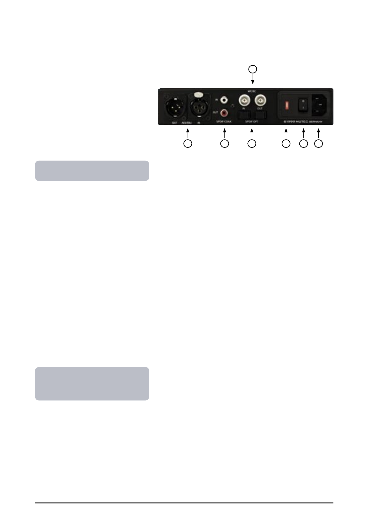
The fuse holder can be found on the rear of the unit, just below the compartment marked »230 V (115
V)«. Use the fuse holder to adjust the required mains voltage. Ex factory, the unit is normally equipped
with a 230-V mains fuse. If the unit needs to be adjusted to 115 V, the fuse must be replaced as de-
scribed in the appendix section »Replacing the mains fuse«.
Please use the enclosed power cord (see packaging) to connect the unit to the mains. Switch the unit
off before you attempt to connect it to the mains. Connect the power cord to the unit, then to a stand-
ard 3-pin mains outlet. To draw the power cord, never pull on the cable but on the mains plug! For
information on the power-inlet wiring, refer to the »Wiring of connectors« section in the appendix.
Disconnect the device from the mains when not using it for an extended period!
Declaration of Conformity
We herewith confirm that the product complies with the European
Commissions standards on electromagnetic compatibility.
Interference emission: EN 50081-1, 1992
Resistance to interference: EN 50082-1, 1992
Presupposed as operation condition is that all clock outputs are con-
nected with high-quality and good shielded BNC 75 ohms cable.
This symbol, an exclamation mark inside a triangle,
alerts you to important operating or safety instructions
in this manual.
!
RISK OF
ELECTRICAL SHOCK!
CAUTION
!
This symbol, a flash of lightning inside a triangle, alerts
you to the presence of uninsulated dangerous voltage
inside the enclosure - voltage that may be sufficient to
constitute a risk of shock.


CONTENT
INTRODUCTION
General Function Description . . . . . . . . . . . . . . . . . 7
Functions . . . . . . . . . . . . . . . . . . . . . . . . . . . . 7
Applications. . . . . . . . . . . . . . . . . . . . . . . . . . . 7
CONTROL ELEMENTS
SMART CLOCK Front Panel. . . . . . . . . . . . . . . . . . . 8
SMART CLOCK Rear Panel . . . . . . . . . . . . . . . . . . . 9
INSTALLATION
Content of the Box . . . . . . . . . . . . . . . . . . . . . . . 10
Placing the Device . . . . . . . . . . . . . . . . . . . . . . . 10
Wiring the Word Clock and Video Interfaces . . . . . . . . . 10
Wiring the AES/EBU and S/PDIF Interfaces . . . . . . . . . . 11
OPERATION
Functional Areas + Parameters . . . . . . . . . . . . . . . . 12
Operating the FORMAT CHANGER advanced . . . . . . . . . 12
Parameters in the AUDIO INPUT Area. . . . . . . . . . . . . 13
Parameters in the SYNC SOURCE Area . . . . . . . . . . . . 13
Parameters in the OUPUT FREQ (-UENCY) Area. . . . . . . . 14
Parameters in the SCMS Area . . . . . . . . . . . . . . . . . 14
STATUS Area + Frequency Analyses . . . . . . . . . . . . . . 15
APPENDIX
Pin Assignment of the Connectors . . . . . . . . . . . . . . 17
Ground-lift Word Clock Input . . . . . . . . . . . . . . . . . 17
Replacing the Mains Fuse . . . . . . . . . . . . . . . . . . . 18
Technical Data . . . . . . . . . . . . . . . . . . . . . . . . . 18
Schematic Diagram . . . . . . . . . . . . . . . . . . . . . . . 19


�������������������������������������������������������������������� ��
�
��������������������������������������������������������������������
INTRODUCTION
Thank you for purchasing the digital audio format and sampling rate
converter FORMAT CHANGER advanced from MUTEC GmbH.
General function description
The FORMAT CHANGER advanced from our SMART DIGITALs Series helps
you interconnect digital audio devices with different transmission formats,
sampling rates and connecting elements. The standard version is equipped
with S/PDIF (optical and coaxial) and AES/EBU interfaces.
The format-only conversion involves not only the necessary electrical
conversion but also a format conversion of the signals, in compliance with
the specifications standardized by the Audio Engineering Society (AES) and
the International Electrotechnical Commission (IEC). The signal from the
selected input is converted in its format and simultaneously sent to all three
output interfaces.
In sampling rate conversion mode the FORMAT CHANGER advanced can be
Word Clock or Word Clock x 256 (so-called Super Clock) synchronized exter-
nally as well as through an audio signal provided at any one of the freely
selectable audio inputs. If no external sync signal is available, the unit can be
set to internal synchronization mode with six different reference frequencies.
Basically, all operating modes allow you to process signals with a sampling
rate ranging from 32 kHz to 108 kHz and a word length of up to 24 bits
(linear, input and output). When synchronized externally, the FORMAT
CHANGER advanced offers a varispeed function for the frequency range
mentioned above.
In addition to the real-time sampling rate display of incoming audio or
clock signals, various operating statuses can be controlled visually by means
of status LEDs. SCMS copy bits can be placed or filtered manually. Addition-
ally, the status of incoming SCMS copy bits (original or 1st generation) is
signaled by LEDs.
In all operating modes, constant jitter, level and edge compensation is
applied to all outgoing signals.
Features
Conversion of the two standardized 2-channel digital audio formats
S/PDIF (optical and coaxial) and AES/EBU.
Simultaneous format conversion on all three outputs with one audio
input selected as the signal source.
Real-time sampling rate conversion, independent of the incoming sam-
pling rate and with six selectable frequencies available (32 kHz 96 kHz).
External synchronization based on Word Clock, Word Clock x 256
(so-called Super Clock) or the clock frequency of a digital audio signal
present at any one of the freely selectable audio inputs.
Interface conversion: OPTO CINCH XLR.
Varispeed-compatible with frequencies from 32 kHz through 108 kHz.
Hard-bypass of sampling rate converter allows format-only conversion.
Real-time frequency analysis and indication of the sampling rate of incom-
ing audio signals or of clock signals used for external synchronization.
Placing/filtering of SCMS copy bits, incl. status display.
Jitter, level and edge compensation applied to all outgoing signals.
Last function selected is retained after power-down.
Applications
Realtime format and sampling rate conversion
Integration of non-synchronizable devices into digital studio
environments
Jitter reducing and signal stabilization
Clock extraction
Variation of SCMS copy bits
Signal distribution
7
Boxes which contain a triangle
with an exclamation mark in the
inside should be read carefully!
These include additional information which
are of major importance for the functional
descriptions in the text column.
!
The grey boxes contain supplementary
informationen for the corresponding
sections in the text columns. The content of
the individual box refers to the description
in the text column beside the box.

������������������
��������������������������������������������������������������������
�������������������������������������������������������������������� ��
8

�������������������������������������������������������������������� ��
�
��������������������������������������������������������������������
CONTROL ELEMENTS
FORMAT CHANGER advanced Front Panel
1 POWER
This red LED lights up when the unit is switched on with the rear-panel
POWER switch (on condition that the adjusted voltage matches your local
voltage).
2 DATA
Use this key to select a function from a specific functional area.
3 SELECT
This key selects one of three functional areas available.
4 AUDIO INPUT
This is the first functional area. Here, you can select one of the three audio
inputs whose audio signal will be processed. Use option #4 in this area to
mute all outputs (TEST MUTE).
5 SYNC SOURCE
This is the second functional area, which allows you to determine the active
status of the sampling rate converter and/or its clock source. You can select
an internal or external clock, or hard-BYPASS the sampling rate converter
to allow for the conversion of signal formats only.
6 OUTPUT FREQ(UENCY)
The third functional area controls the output sampling rate applied to the
output copy of the incoming audio signal. This functional area is available
exclusively in INTERNAL SYNC mode.
7 STATUS
This is no real functional area but indicates various device statuses by means
of status LEDs.
8 AUDIO + SYNC INPUT FREQ(UENCY)
Here, the display reads in real time either the sampling rate of the signal
present on the selected audio input or the frequency of the external clock
signal.
9 SCMS
This area allows you to monitor the status of the incoming audio signal
with regard to any SCMS copy bits it may contain.
10 SCMS
Use this key to manually remove SCMS copy bits from the incoming S/PDIF
audio signal or add such data to the outgoing S/PDIF audio signal.
Refer to the OPERATIONS chapter for more
information.
9
8
910
1
64
3
2
5
7

�������������
��������������������������������������������������������������������
��������������������������������������������������������������������
��
FORMAT CHANGER advanced Rear Panel
1 AES/EBU IN + OUT
These interfaces receive/transmit balanced digital AES/EBU audio signals
based on the specifications of the standard AES 3-1992. The input/output
impedance is 110 Ω (XLR connector, male + female).
2 S/PDIF COAX IN + OUT
These inputs/outputs receive/transmit unbalanced digital S/PDIF audio
signals (coaxial) based on the electrical specifications of the standard IEC
60958. The input/output impedance is 75 Ω. (cinch connectors).
3 S/PDIF OPT IN + OUT
These inputs/outputs receive/transmit digital S/PDIF audio signals (optical)
in accordance with the specifications of the standard IEC 60958 (Toshiba
Toslink connector, EIAJ standard).
4 WC / SC IN + OUT (Word Clock + Word Clock x 256, so-called Super Clock)
This input receives a Word Clock or Word Clock x 256 signal (automatic dif-
ferentiation) for the synchronization of the FORMAT CHANGER advanced.
The incoming clock signal is processed electrically and immediately sent to
the WC/SC output for the synchronization of connected devices. If no exter-
nal clock signal is applied, the WC/SC output provides the sampling rate of
the incoming digital audio signal as the Word Clock frequency. The input/
output impedance is 75 Ω, the input impedance can be disabled internally.
5 230 V (115 V)
This compartment houses the mains fuses, which must be inserted in ac-
cordance with the local voltage used for operating the unit! See also the
safety instructions, in particular, the chapter OPERATION, and the section
»Replacing the Mains Fuse« in the appendix.
6 POWER switch
Mains power switch. Be sure to connect the unit properly to the mains by
using the enclosed power cord and select the country-specific mains volt-
age by inserting a mains fuse of the correct type and rating (5) before you
attempt to operate the unit. Please read the safety instructions.
7 Mains connector
Use this receptacle to connect the enclosed power cord. Be sure to set
the POWER switch to OFF and insert a mains fuse of the correct type and
rating, before you connect the power cord to the unit and/or wall outlet.
The section »Pin Assignment of the Connectors« in the appendix provides
you with information on how to wire the various connecting elements.
Refer to the OPERATIONS chapter for more
information.
For detailed specifications on all terminals,
refer to the PIN ASSIGNMENT OF THE
CONNECTORS and TECHNICAL DATA sections
in the appendix.
10
7
532 6
4
1

�������������������������������������������������������������������� ��
�
��������������������������������������������������������������������
INSTALLATION
Content of the Box
The unit was packed carefully. Nevertheless we recommend to check the
content directly after opening the package:
1 x FORMAT CHANGER advanced
1 x Power cable
4 x Rubber feets
1 x Manual
1 x Registration card
Placing the Device
The unit should be set up as closely as possible to the devices to which it
will be connected, so as to avoid excessive cable lengths. Use the 4 rubber
feets enclosed with the appliance and stick them symmetrically on the
bottom side of the unit to protect the enclosure and supporting surface
from being damaged. When the unit is installed in a rack, the rubber feets
should not be used to save space!
For 19 rack installation MUTEC offers an optional set of rack ears
(MW-01/19 order no. 8020-005). Install the device so that one unit of rack
space is left free above the device to allow for sufficient ventilation! The
mounting depth including the terminals is 180 mm/7.07.
Another 150 mm/5.9 should be added for the required cables.
Never expose the device and accessories to rain, moisture, direct sunlight,
or excessive heat produced by radiators, heaters, or spot lights! Sufficient
air circulation in the environment of the device must be ensured!
Wiring the Word Clock Interfaces
To allow for the synchronization of signals, the interfaces of all devices
involved must be properly connected to each other, so as to ensure a logi-
cal signal flow. Always be sure to connect the Word Clock output of the
FORMAT CHANGER advanced to the corresponding input of the devices you
wish to synchronize! Cable lengths should be kept as short as possible to
minimize signal losses and/or interferences!
For the transmission of Word Clock signals electrical, unsymmetrical cables
with a resistance of 75 Ω and BNC connectors on both ends are used. Typi-
cally, such cables are marked »RG-59U, RG59B/U«.
Additionally, you should make sure that the Word Clock inputs to be con-
nected to the FORMAT CHANGER advanceds output have a 75 Ω termi-
nating resistor! Most Word Clock inputs allow for enabling/disabling the
termination with a so-called »termination-switch«, which may be located
on the outside or inside of the device.
For devices which have no termination of the Word Clock input, e.g. RME
Hammerfall with Word Clock i/o or Alesis BRC, you can use an additional
BNC-T piece to terminate the input. Plug the T piece with its center connec-
tor into the input of the receiving device. Then, connect the cable coming
from the FORMAT CHANGER advanced to one of the lateral connectors,
and the other connector of the BNC-T piece to a 75 Ω resistor forming the
BNC termination.
Basically, you should avoid »looping through« Word Clock leads by means
of passive BNC-T pieces to preserve the signal quality, as level drops will be
the result. If there is no other way to wire your set-up, please make sure
that all Word Clock inputs (except for the last device in the chain) have
their terminations disabled! In a serial Word Clock chain only the last clock
input should have a termination! Never connect more than three devices in
series to one output!
Additionally the condition of the
packaging material and the device
should be checked carefully. If there
are any damages please refer to SAFETY
INSTRUCTIONS, Initial Operation, and
WARRANTY REGULATIONS.
!
Before installing the unit finally
the section SAFETY INSTRUCTIONS
located at the beginning of this
manual should be read.
!
It is imperative that the lengths
of all cables connected are largely
the same, as this is the only way to
ensure that all devices will be synchronized
in phase (exception: cable tolerances).
Please make sure that the cable used has a
resistance of 75 Ω, in compliance with the
specifications! If a cable with a different
resistance is used, a dramatic deterioration
of the signal quality can be the result! In
this case, the perfect synchronization of all
devices involved could be impaired.
!
We recommend using high-grade cables
with a good shielding for your clock signal
leads, in particular, if you need to transmit
Word Clock x 256 (so-called Super Clock)
signals over greater distances. In any case, a
length of max. 10 meters (approx. 30 feets)
should never be exceeded!
11

������������
��������������������������������������������������������������������
��������������������������������������������������������������������
��
Wiring the AES/EBU and S/PDIF Interfaces
Connect the AES/EBU interfaces with the help of balanced electrical cables
equipped with XLR connectors on both ends. The specifications stipulate a
specific cable resistance of 110 Ω (ask your retailer for a confirmation of this
value when purchasing the cables).
Connect the coaxial S/PDIF interface with the help of unbalanced electri-
cal cables equipped with cinch connectors on both ends. The specifications
stipulate a specific cable resistance of 75 Ω (ask your retailer for a confirma-
tion of this value when purchasing the cables).
Connect the optical S/PDIF interface with the help of Toshiba TOSLINK-
compliant optical fiber cables. Here, you can use both plastic and glass
fiber-based cables. When using plastic fiber cables, lengths of 10 meters
should not be exceeded, so as to ensure the reliable transmission of signals.
Glass fiber cables can transfer data reliably even over greater distances.
MUTEC offers optical cables of various
lengths that have been specifically tested
for the transmission of S/PDIF and ADAT
signals (retailers and distributors only)!
Since some manufacturers offer optimized
cables for the transmission of digital S/PDIF
and AES/EBU audio signals, it will be a good
idea to ask your retailer for specific cables.
12

�������������������������������������������������������������������� ��
�
��������������������������������������������������������������������
OPERATION
Functional Areas + Parameters
Your FORMAT CHANGER advanced provides four functional areas:
AUDIO INPUT
SYNC SOURCE
OUTPUT FREQUENCY
SCMS
Each of these functional areas comprises a variety of different parameters.
As an example, the illustration in the margin shows the functions included
in the functional area SYNC SOURCE.
After initial power-up of the unit the following parameters are preset in
the four functional areas (LEDs light up permanently):
Functional area AUDIO INPUT
Default parameter: S/PDIF OPT
Functional area SYNC SOURCE
Default parameter: BYPASS
Functional area OUTPUT FREQUENCY
Default parameter: 44,100 Hz
Functional area SCMS
Default parameter: SCMS not placed
Operating the FORMAT CHANGER advanced
After initial power-up of the unit, the LEDs of the functions selected (see
above) in the three functional areas light up permanently. Press the DATA
or SELECT key to edit one of the preset functions. Subsequently, the LED of
the preset function in the first functional area starts flashing, which signals
that you can now select another function or functional area.
SELECT key
The SELECT key is used to select one of the three functional areas. After
selection of a different functional area, the LED of the last function
selected in this area starts flashing. When you quit a functional area by
pressing the SELECT key again, the LED of the last function selected lights
up permanently.
DATA key
The DATA key is used to select a function from a specific functional area.
Use the upper key to select the functions above the current position, and
the lower key to select the functions below that position. Once a function
has been selected, its LED starts flashing.
If you press neither the DATA nor SELECT key for about 4 seconds, the LED
of the last function selected lights up permanently. To select a function
you must re-initiate SELECT mode now by pressing the SELECT key again.
Subsequently, the LED of the last function selected starts flashing. Press the
SELECT key again to select a new functional area, or the DATA key to select
a new function.
Parameters in functional area
Functional area
Parameters inclu-
ded in functional
area
When you select a new function, the
FORMAT CHANGER advanced remains in
the current functional mode, until the LED
of the new function selected has stopped
flashing. No further confirmation (ENTER
command, etc.) is required.
13
Functional areas

������������
��������������������������������������������������������������������
��������������������������������������������������������������������
��
Parameters in the AUDIO INPUT Area
S/PDIF OPT, S/PDIF COAX, AES/EBU
This functional area includes the three input formats mentioned above
for the digital audio signal to be received. The input interfaces avail-
able are listed in the section »CONTROL ELEMENTS, FORMAT CHANGER
advanced Rear Panel«
When you select an input connected to a feeding device, the FORMAT
CHANGER advanced initiates the simultaneous signal transfer to all three
output formats, which involves the electrical conversion between the two S/
PDIF interfaces as well as the format conversion from S/PDIF to AES/EBU, and
vice versa. At the same time, the sampling rate contained in the audio signal
is extracted and sent to the WC/SC output as a Word Clock signal, so that you
can synchronize the devices connected to this output to the incoming audio
signal.
The incoming audio signals quality is monitored by the system. Whenever
a usable signal is applied to the selected input, the red status LED AUDIO IN
in the STATUS area lights up.
If the audio signal contains emphasis information, the red status LED
EMPHASIS in the STATUS area lights up. In this case, the FORMAT CHANGER
advanced does not process the data status to maintain signal transparency
on the output sid further confirmation (ENTER command, etc.) is required.
The transfer of digital audio signals from the selected input to all three
outputs also ensures that the input signal can be used for further process-
ing on the output based on the same format. Since the output signal is
processed electrically in this case, the FORMAT CHANGER advanced can
also be used to refresh the incoming signal.
TEST MUTE
This function mutes all outputs of the FORMAT CHANGER advanced, which
includes not only the digital audio outputs but also the WC/SC output. Use
the function to configure your equipment set-up, so as to identify possible
problems caused by interconnected signals or interference.
Parameters in the SYNC SOURCE Area
BYPASS
In BYPASS mode the FORMAT CHANGER advanced works exclusively as
a format converter, bypassing the sampling rate converter in the signal
path.
S/PDIF OPT, S/PDIF COAX, AES/EBU
These parameters refer to the three digital audio inputs whose signals
are used as clock frequencies for the external synchronization of the
FORMAT CHANGER advanced. The unit processes digital audio signals
or S/PDIF and/or AES/EBU blank-frame signals, which also involves the
sampling rate converter!
When you select one of the three audio inputs as the clock source in the
SYNC SOURCE area, the FORMAT CHANGER advanced is synchronized to
the sampling rate included in the audio or blank-frame signal applied here.
In parallel to that, the sampling rate is sent as a Word Clock signal to the
WC/SC output for the synchronization of other devices. Now, the digital
audio input signal selected for processing in the AUDIO INPUT area is sent
to all three audio outputs; it has the same sampling rate as the audio or
blank-frame signal used for synchronization and is totally independent of
the original sampling rate!
WC/SC
Use this parameter to activate the WC/SC input on the rear of the FORMAT
CHANGER advanced and to synchronize the unit with an incoming clock
signal received at this input. You can feed in both Word Clock and Word
Clock x 256 (so-called Super Clock) signals, the input stage distinguishes
automatically between the two variants. In this mode, the digital audio
signal selected in the AUDIO INPUT area is synchronized with the sampling
rate of the incoming Word Clock or Word Clock x 256 signal, converted in
its format and sent to all three audio outputs - irrespective of its original
sampling rate!
If you wish to route the incoming clock signals to other equipment as
well, you need to lift the ground of the WC/SC input before. Please follow
the instructions given in the appendix, section »Ground-lift«.
Parameters in AUDIO INPUT area
If the incoming audio signal is interrupted
or the system detects an increase in the
error rate, the status LED ERROR MUTE in
the STATUS area lights up, while the AUDIO
IN LED goes out. At the same time, all audio
outputs and the WC/SC output are muted to
protect your monitor speakers or head-
phones from damage caused by erratic level
fluctuations.
Parameters in SYNC SOURCE area
The selection of one of the three audio
inputs as a clock source in the SYNC
SOURCE area is independent of the audio
input selected as the audio signal source in
the AUDIO INPUT area.
A Word Clock signal present at the WC/SC
input is routed in parallel to the WC/SC
output for the synchronization of other
equipment. For reasons determined by the
system any Super Clock signal applied here
will also be output as a Word Clock signal!
14

������������
��������������������������������������������������������������������
��������������������������������������������������������������������
��
Please note that this function may
not be used for unauthorized copy-
ing of any kind of data material!
!
INTERN SYNC
This function activates the clock oscillator built into the FORMAT CHANGER
advanced. In this mode, any clock signal applied to the inputs mentioned
above will be ignored. Independently of the incoming audio signals sam-
pling rate, you can now determine the exact sampling rate of the outgoing
audio signals. For this purpose, you need to select the function and then
switch over to the functional area OUTPUT FREQ (see below).
Parameters in the OUTPUT FREQ (-UENCY) Area
This functional area will be active only if the function INTERN SYNC in the
SYNC SOURCE area has been selected before. Independently of the incom-
ing audio signals sampling rate, you can now adjust one of the six output
sampling rates available. Since these rates are coupled to the internal high-
precision clock oscillator, they are generated with constant accuracy, even if
there are fluctuations in the audio signals sampling rate. The rate adjusted
here is simultaneously sent to the WC/SC output as a Word Clock signal for
the synchronization of equipment connected there.
The clock rates generated by the internal clock oscillator of your FORMAT
CHANGER advanced feature a temperature-compensated stability of +/- 10
ppm, which corresponds to the specifications of AES 11, Grade 2 (!). Thus
you can use the FORMAT CHANGER advanced even in smaller set-ups as
a master clock for the synchronization of other equipment. If one clock
output is not enough for your specific application, please consider using
our DISTRIBUTOR ws for the distribution of clock signals (see enclosed
brochure).
Parameters in the SCMS Area
In this functional area you can manually place SCMS copy bits and monitor
their status.
As is generally known, SCMS copy bits are exclusively defined in S/PDIF data
streams to prevent multiple copies of the digital audio material. As a result,
copy bits can only be placed into or removed from outgoing S/PDIF signals.
The AES/EBU specifications have no additional bits defined in the audio
material that prevent unauthorized copying.
Before you place SCMS copy bits, you should check the incoming audio
signal for existing SCMS data. For this purpose, the FORMAT CHANGER
advanced has two red status LEDs marked ORIG and 1st, which indicate
the current SCMS status of the incoming audio signal. This function works
independently of the general operating mode of the unit.
The SCMS copy bit system distinguishes originals (the bits placed to
represent the original version of the audio material) from 1st generation
copies (the bits placed to represent the first copy of the original). Conse-
quently, any audio material marked as 1st generation material cannot be
copied any longer via S/PDIF interfaces.
When working in a recording studio environment, you will usually need to
be able to easily exchange digital audio material between different devices,
which is why the FORMAT CHANGER advanced always erases copy informa-
tion contained in the channel status block of the outgoing audio signal,
which also includes SCMS copy bits. If you wish to protect your audio mate-
rial from unauthorized copying via S/PDIF interfaces, simply press the SCMS
key, so that the SET LED (green) lights up signaling that the outgoing audio
signal will be marked as 1st generation material.
Since the FORMAT CHANGER advanced
stores all settings even after power-down,
you should press the SET key again upon
completion of an SCMS-coded recording,
in order to disable this function and allow
for the free exchange of audio material
between the various devices in the studio.
Parameters in OUPUT FREQ (-UENCY) area
Parameters in SCMS area
15

������������������
��������������������������������������������������������������������
�������������������������������������������������������������������� ��
STATUS Area + Frequency Analysis
This functional area provides you with information on various operating
statuses of your FORMAT CHANGER advanced.
AUDIO IN
This LED lights up as soon as a usable digital audio signal is present at the
audio input selected.
EMPHASIS
If the audio input signal contains emphasis information, the status LED
EMPHASIS lights up. In this case, the FORMAT CHANGER advanced does not
process the data status to maintain signal transparency on the output side.
EXTERN SYNC
This LED lights up whenever a usable Word Clock, Word Clock x 256 or
digital audio signal is present at the clock input selected in the SYNC
SOURCE area.
ERROR MUTE
Whenever a signal in one of the functional areas is interrupted or the
incoming signal suffers from an increased error rate, the FORMAT
CHANGER advanced mutes all of its outputs (ERROR MUTE LED lights up),
so as to protect your monitoring speakers or headphones from damage
caused by erratic level fluctuations.
AUDIO/SYNC INPUT FREQ(UENCY)
Depending on the operating mode selected, this display shows in real time
the sampling rate of either the audio signal from the selected audio input,
or of the incoming clock signal.
When the BYPASS function in the SYNC SOURCE area is on, the display
reads the sampling rates of the incoming audio signal. In this mode, the
FORMAT CHANGER advanced does not display the rate of clock signals,
even if they are present, because it works exclusively as a format converter.
If the WC/SC input or one of the audio inputs is selected as a clock input
in this area, the applied clock signal is displayed, because in this mode the
sampling rate converter is enabled and the incoming audio signals rate is
adapted to the clock signal.
Parameters in STATUS area
16

�������������������������������������������������������������������� ��
�
��������������������������������������������������������������������
17
APPENDIX
Pin Assignment of the Connectors
MAINS
3
2
1
1
3
2
1 Live, phase (brown; USA: black)
2 Protective earth (green/yellow; USA: green)
3 Neutral (blue; USA: white)
AES/EBU XLR-Output AES/EBU XLR-Output
CINCH: OUPUT BNC-OUTPUT
1 Audio signal 1 Signal
2 Audio ground 2 Ground
2
1
1
2
1 Audio ground
2 a conductor (hot / +)
3 b conductor (cold / -)
2
3
1
1 Audio ground
2 a conductor (hot / +)
3 b conductor (cold / -)
Ground-lift of Word Clock Input
Place the unit, front panel towards you, on a table and remove the steel-
plate cover after unscrewing the six screws holding it. Locate the BNC jacks
on the rear of the unit (see WC/SC) and follow them all the way inside the
enclosure. Locate the DIP switch next to the BNC connectors (standard posi-
tion: »ON«). Carefully set the switch to position »OFF« to lift the ground of
the Word/Super Clock input.
CAUTION! Disconnect the unit from
the mains before opening!
Remount the steel-plate cover
thoroughly before you attempt to
operate the unit!
!
!

������������
��������������������������������������������������������������������
��������������������������������������������������������������������
��
18
Replacing the Mains Fuse
Disconnect the power cord from
both the wall outlet and the unit
before you attempt to replace the
mains fuse!
Make sure that the fuse holder is inserted
completely down to the bottom of its socket
and that the compartment is fully closed!
!
Use a small, flat-blade screwdriver to open the compartment that houses
the fuse holder. Carefully pull out the fuse holder from its socket. Turn it
by 180° and re-insert it into its socket. After closing the compartment, the
second mains voltage marker must be visible through the window in the
compartment cover.
Technical Data
S/PDIF OPTICAL INPUT
Interfaces 1 x Toshiba ToslinkTM, EIAJ RC-5720
Format IEC 60958
Resolution 16 24 bits
Lock range 32.0 kHz to 108.0 kHz
S/PDIF COAXIAL INPUT
Interface 1 x Coaxial (Cinch/RCA female), unbalanced, input impedance 75 Ω, 200 mV 7 V
Format IEC 60958
Resolution 16 24 bits
Lock range 32.0 kHz to 108.0 kHz
AES/EBU INPUT
Interface 1 x XLR female, transformer balanced, input impedance 110 Ω, 200 mV 7.0 V
Format AES/EBU 3 1992 + AES/EBU 11 1997
Resolution 16 24 bits
Lock range 32.0 kHz to 108.0 kHz
S/PDIF OPTICAL OUTPUT
Interface 1 x Toshiba ToslinkTM, EIAJ RC-5720
Format IEC 60958
Resolution 24 bits
Transmitted audio clock rates Every clock rate from 32.0 kHz to 108.0 kHz
S/PDIF COAXIAL OUTPUT
Interface 1 x Coaxial (Cinch/RCA female), unbalanced, 0.5 Vpp @ 75 Ω, output impedance 75 Ω,
buffered
Format IEC 60958
Resolution 24 bits
Transmitted audio clock rates Every clock rate from 32.0 kHz to 108.0 kHz
AES/EBU OUTPUT
Interface 1 x XLR male, transformer balanced, 3,5 Vpp @ 110 Ω, output impedance 110 Ω, buffered
Format AES/EBU 3 1992
Resolution 24 bits
Transmitted audio clock rates Every clock rate from 32.0 kHz to 108.0 kHz
WORD CLOCK INPUT
Interface 1 x BNC, 200 mV-7 V, unbalanced, input impedance 75 Ω + 1MΩ, switchable
Lock range 32.0 kHz to 108.0 kHz; 8.0 MHz to 13.0MHz, automatic selection
WORD CLOCK OUTPUT
Interface 1 x BNC, 3,5 V, unbalanced, input impedance 75 Ω, buffered
Transmitted audio clock rates Every clock rate from 32.0 kHz to 108.0 kHz + 8.0 MHz to 13.0MHz

������������
��������������������������������������������������������������������
��������������������������������������������������������������������
��
19
INTERNAL REFERENCE OSCILLATOR SPECIFICATIONS
Oscillator type TCXO, temprature com pensated crystal oscillator, burned-in and pre-aged
Clock accuracy (shipped) < ± 10.0 ppm, aligned to AES 11, grade 2
Generatable clock rates 32.0 kHz, 44.1 kHz, 48.0 kHz, 64.0 kHz, 88.2 kHz, 96.0 kHz
Operating temperature - 10°C to + 60°C
SIGNAL PROCESSING
Format conversion S/PDIF (optical) ↔ S/PDIF (coaxial) electrical conversion
S/PDIF (optical & coaxial) ↔ AES/EBU digital format conversion
Samplerate conversion ratio 1 : 3 to 3 : 1
Dynamic range 128 dB
External synchronisation Word Clock + Word Clock x 256; All digital audio inputs (clock extraction)
Fully varispeed compatible
SCMS copy bit Detection original + 1. generation; setting + removing
POWER SUPPLY
Type Internal power supply
Input voltage 115 V/230 V (switchable), 50-60 Hz
Power consumption max. 12 W, removable power cord (IEC320/C13 aligned)
SYSTEM UNIT COVER
Cover size / material / color 196 mm x 42 mm x 156 mm (W x H x D); aluminium sheet; black
Front panel size / material 198 mm x 44 mm x 2 mm (W x H x D), 7.8; aluminium anodized
Weight ~ 1550 g
Schematic Diagram
OPTO IN
COAX IN
AES IN
MUX
MUX
RX
I2SO
RX
I2SO
TX
I2SI
3
Clk
1
SDO
MUX
3
Clk
MUX
1
SDI
MUX
3
Clk
1
SDO
MUX
3
Clk
MUX
SDI
TX
I2SI
Cs8427
Cs8420
OSZ
Teiler1
Teiler2
PLL
SC/WC DETECT
Bidirekt.
SC/WC IN
OPTO OUT
COAX OUT
AES OUT
SYNC
SRC
SC/WC OUT
SC/WC
Ctrl.
Ctrl.
Ctrl.
Ctrl.
Ctrl.
Ctrl.
Ctrl.
Ctrl.
Cs8420 Ctrl.
Ctrl.
Ctrl.
EXTSync.
MCU
LEDS
23 St.
TASTER
4 St.
4
10 MUX 8:4
CPLDMuxCtrl.
8420 Ctrl/Data
EXTsync.
FREQUENZ
DETECTION
7 Segment
EEPROM
1
2
CPUClk
Teiler 3
Logik in
CPLD
XC 95144XL
© MUTEC GmbH 2000

�������������������������������������������������������������
Table of contents
Other Mutec Media Converter manuals
Popular Media Converter manuals by other brands

Moxa Technologies
Moxa Technologies IMC-21A IMC-21A Quick installation guide

Relectronic
Relectronic LMC-55 Installation

Delta Electronics
Delta Electronics PMC Series instruction manual

CYP
CYP AU-22DD Operation manual

Crestron
Crestron DM-NVX-E30 product manual

Interlogix
Interlogix ACL800FL-CONV-W-RS485 installation manual