© MuxLab Inc. 2017
Installation
For the Receiver (RX), connect a pair of 8 ohms speakers. Connect the included power supply (the
RX is not PoE) before connecting it to the AC. For more information on how to configure the unit
and the Ethernet switch, check Muxlab’s website, the 500811 Operation Manual and the 500755-
AMP-TX Quick Installation Guide.
Caution: Do NOT connect (short) any output signal wires together or to the ground.
Do not block the ventilation holes.
Verify that the UTP cable to be used is Cat5e/6 or better for LAN use, and is not intended for
telephone equipment.
Do not attempt to open the housing. There are no user-serviceable parts inside the amplifier.
Opening the unit will void your warranty.
1. Use a Cat 5e/6 UTP cable between the Receiver and the 1Gig Ethernet Switch.
2. It is recommend to use the Receiver with speakers with impedance of 8 ohms and a rating of 50W
minimum. Higher impedance will work but less power will be available but a lower impedance can
overheat and damage the unit.
3. Use wires with at least 18 AWG (ideally from 12 to 18 AWG) to connect the speakers to the
Receiver amplifier binding posts. Any standard electrical wire with minimum gage is
acceptable but a larger gauge is better. Limit the distance to less than 15ft (5m).
4. Turn the Volume Preset screw (located on the front of the unit) to maximum.
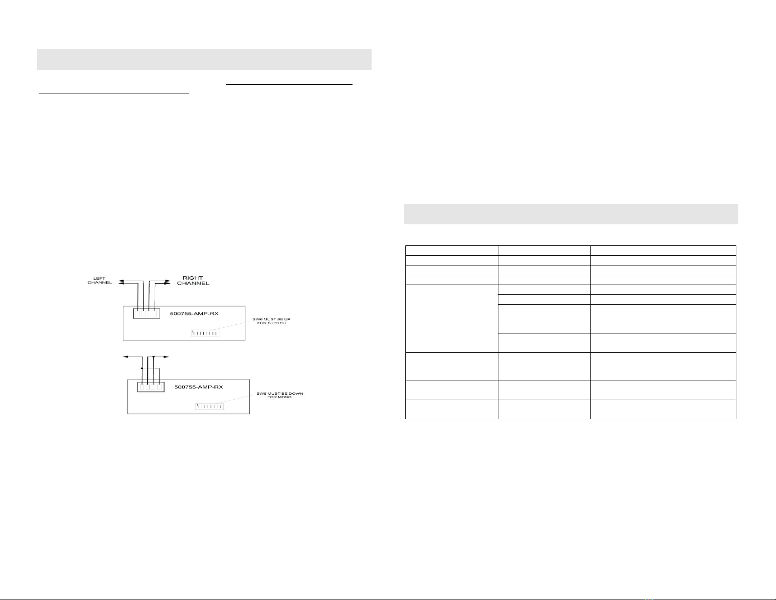
5. Speaker connection: (top portion: for stereo, bottom portion: for mono)
6. If configuration is point-to-point: use the DIP Switches to select a unique Device ID (DIP
switch positions #1, #2 and #3) for each Transmitter present on the network and configure
each Receiver Device ID to the corresponding selected Transmitter. An Ethernet switch is not
required but may be used. Note that this step is not necessary if the MuxLab Network
Controller (500811) is used.
7. If the configuration is a point-to-multipoint or multipoint-to-multipoint:
You will need to use an Ethernet Switch with 1Gig ports and DHCP Server support. In
addition IGMP Protocol support is required for the multipoint-to-multipoint case. Verify that
the Ethernet Switch is configured correctly and that the DHCP Server is enabled and
that the IGMP Protocol is enabled for multipoint-to-multipoint applications. See the
support documentation on MuxLab’s website regarding how to configure an Ethernet.
8. Power ‘ON’ all units.
9. Power ‘ON’ the audio equipment and verify the sound quality.
An IR Emitter and Sensor is not included, but may be purchased separately. If purchased, IR
control signals may initiate from control software on a PC, tablet, or smartphone connected to
the network, so that only IR Emitters are required next to the audio equipment. You can
differentiate the IR Sensor and the IR Emitter by looking at the 3.5 mm plug. The IR Sensor
is using a Stereo Plug (3 Contacts) and the IR Emitter a mono plug (2 Contacts). Set the IR
direction (Dip switch position #5, set to ON=Emitter, or OFF=Sensor). The IR direction
setting is read each time the unit is powered ON, always set DIP switch position #5 while the
unit is OFF in order for the setting to take effect during power ON.
10. Position the IR Sensor so that it is directed at the hand-held remote control. For a clear IR
signal reception, aim the hand-held remote control at the top of the IR Sensor enclosure.
11. Position the IR Emitter as close as possible to the source’s IR Sensor. For a clear IR signal
reception, the IR Emitter can be glued on the source’s IR Sensor. The IR Emitter’s signal is
transmitted from the side of the enclosure.
12. This product supports RS232 bidirectional communication. The default settings are 9600, N,
8, 1. To send an RS232 packet to a specific device, you need to put the IP address in front of
the packet. This communication is meant to be machine to machine; and hexadecimal codes
must be used. For example, to send the message “Hello” to a device having an IP address of
192.168.168.55 IP, send the following hexadecimal string: 0xC0 0xA8 0xA8 0x37 0x48
0x65 0x6C 0x6C 0x6F. (or “192 168 168 55 H e l l o” in hexadecimal).
Troubleshooting
The following table describes possible symptoms, probable causes and solutions regarding the unit:
Check continuity on each pair.
Turn up the front volume screw.
Turn down the front volume screw.
Check RX unit level.
No audio or freezing
audio
Check DIP switch address.
IGMP not enabled or not
working properly
Check the Ethernet switch configuration and
enable the IGMP protocol.
Defective audio cable or
equipment incorrectly
grounded.
Change cable or verify wiring interface.
Try grounding equipment on each side to
safety ground.
Place the unit in a ventilated area.
Wrong speaker impedance, or too low.
Software cannot detect
the 500755-AMP
Computer not on the same
subnet or wrong IP address
Set computer IP Address and mask.
If you still can’t diagnose the problem, please call MuxLab Customer Technical Support at
877-689-5228 (toll-free in North America) or (+1) 514-905-0588 (International).


