EMUGE Speedsynchro Modular/NFC User manual

Speedsynchro®Modular/NFC/IKZ
Speedsynchro®Modular/NFC/MQL
Speedsynchro®Modular/NFC
Operating instruction

Speedsynchro®Modular/NFC
2 Operating instruction edition: 01.09.2022
Contents:
1Application range, safety instructions and technical data............................. 4
1.1 Application range, determined use............................................................................................. 4
1.2 Specifications ............................................................................................................................. 5
1.3 Safety instructions and hints ...................................................................................................... 6
1.4 Proprietary rights ........................................................................................................................ 6
1.5 Dimensions and technical data .................................................................................................. 7
2Putting the Speedsynchro®Modular/NFC into operation............................... 8
2.1 Unpacking................................................................................................................................... 8
2.2 First putting into operation / preparation..................................................................................... 8
Setting the angular position of the stop block.................................................................. 8
Assembly of the coolant-lubricant tube depending on shank type................................ 10
Using the Speedsynchro®Modular/NFC with adjustment screw................................... 11
2.3 Programming notes.................................................................................................................. 13
2.4 Re-putting into operation.......................................................................................................... 14
2.5 Sealing disk .............................................................................................................................. 15
Application ..................................................................................................................... 15
Assembly of the sealing disk......................................................................................... 15
2.6 Collet......................................................................................................................................... 16
Application ..................................................................................................................... 16
Assembly of the collet.................................................................................................... 16
2.7 Assembly of the tap/cold-forming tap....................................................................................... 17
2.8 Remove of the tap/cold-forming tap, clamping nut and sealing disk........................................ 18
3Readout operating data via NFC interface..................................................... 19
3.1 Speedsynchro- Electronics................................................................................................... 19
3.2 Readout operating data............................................................................................................ 19
3.3 Display in the app..................................................................................................................... 20
4Maintenance / Servicing .................................................................................. 22
4.1 Maintenance schedule.............................................................................................................. 22
4.2 External cleaning...................................................................................................................... 22
4.3 Maintenance............................................................................................................................. 22
5Storage when not in use.................................................................................. 23
6Disposal instructions....................................................................................... 23
7EU-Declaration of Conformity......................................................................... 24
8UK Conformity Assessed................................................................................ 25
9FCC-Rules......................................................................................................... 26

Speedsynchro®Modular/NFC
Operating instruction edition: 01.09.2022 3
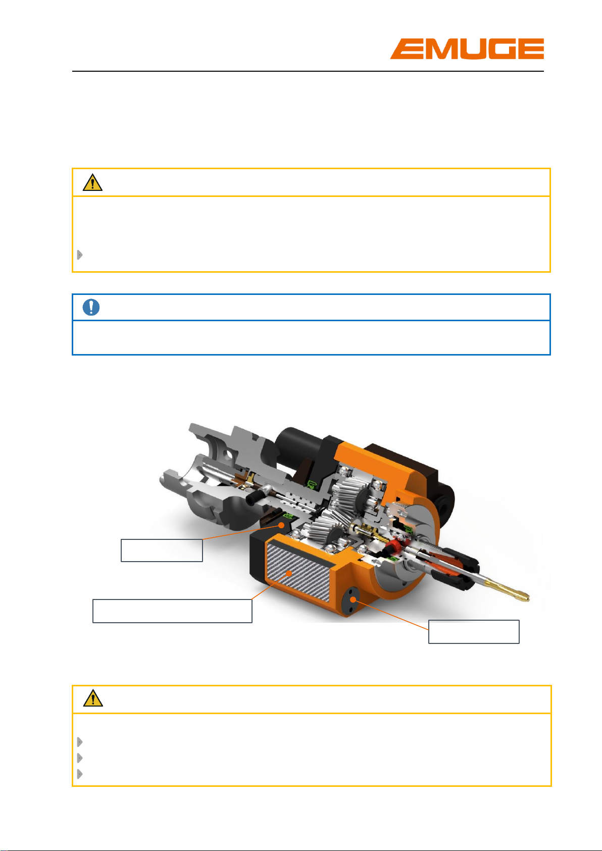
Electronics and NFC Antenna
Sensors
Battery
Warnings, symbols
In this operating instruction the following symbols are used:
Attention
Marks special instructions, rules and prohibitions, which are important in order to avoid
any damage.
Please observe these instructions!
Note
Marks application instructions and other useful information.
Sectional view:
Speedsynchro® Modular/NFC
Attention
Battery:
Not rechargeable
Do not incinerate
Dispose of as prescribed. Please refer to chapter 6, page 23

Speedsynchro®Modular/NFC
4 Operating instruction edition: 01.09.2022
1 Application range, safety instructions and technical data
1.1 Application range, determined use
The collet holders type Speedsynchro®Modular/NFC are used on CNC-machining
centers with synchronous control. They are intended for clamping of taps/cold-forming
taps for thread production.
Normally the Speedsynchro®Modular/NFC are equipped with one of the following
shanks:
Cylinder shank according to DIN 1835 B+E
ABS-clutch
Applicable for cutting range M1 –M8, please refer to Table 1, page 7
The tap/cold-forming tap is locked via the collets according to DIN ISO 15488.
The collets must be chosen depending on the used type and used tap/cold-forming
tap, for more information please refer to chapter 2.6, page 16.
The collet holders type Speedsynchro®Modular/NFC are available as:
IKZ for coolant-lubricant pressures up to 50 bar
MQL for 1-channel or 2-channel - MQL systems, up to 10 bar
For correct use, the Speedsynchro Modular/NFC must be secured against twisting in
the machine spindle. This requires a stop fixture adapted to the machine-side stop
block. For further details, please refer to chapter 2.2 page 8
The non-determined use exempts the manufacturer from any liability.

Speedsynchro®Modular/NFC
Operating instruction edition: 01.09.2022 5
1.2 Specifications
Further characteristics of the Speedsynchro®Modular/NFC:
The Speedsynchro®Modular/NFC uses an integrated gear ratio of 1:4,412. (This
enables the machine spindle to be operated in a lower speed range, thus saving
energy up to 90%)
The integrated minimal length compensation on tension and compression
compensates arising minimal pitch differences between synchronous spindle and
tap/cold forming tap possibly leading to high thread flank friction forces. A possible
increase of axial force during the thread producing cycle is reduced to a minimum.
The resulting advantages are:
- no mis-cutting of the threads
- optimized tool life of tap/cold-forming tap
The Speedsynchro®Modular/NFC has an NFC-Modul (NFC = Near Field
Communication) with integrated electronics. This takes and stores the operating
data. An NFC-enabled smartphone is required to read out the data (not included in
the delivery). For further details please refer to chapter 3, page 19.
Simple programming as synchronous cycle with feed programme adapted to the
transmission ratio.
The reversal of the tap/cold-forming tap is done by the machine spindle:
- no switching components in the Speedsynchro®Modular/NFC
- low wear and longer maintenance intervals
Due to the modular design, the adjustment screw matched to the tool can be
mounted if required, please refer to chapter 2.2.3 , page 11.

Speedsynchro®Modular/NFC
6 Operating instruction edition: 01.09.2022
1.3 Safety instructions and hints
For all works, i.e. putting into operation, production or maintenance, please observe
the details given in the operating instruction.
All relevant safety regulations as well as local instructions are to be observed when
working with the tapping attachments.
Below please find some basic rules:
Attention
Please wear gloves during tool change to avoid injury.
Basically change the tool yourself to avoid the sudden start of the spindle
caused by mis-operating.
Hold the tool when loosening the tool clamping to avoid it falling down and
damaging the tool and the work piece.
Keep the tool adaptation clean.
There are maximum values for cutting speeds and feeds for every kind of
machining. Please observe such data.
Please observe the maximum tool dimensions.
Furthermore, the instructions of the tool manufacturers are valid!
1.4 Proprietary rights
The entire contents of these operating instructions are subject to German proprietary
rights legislation.
Any form of multiplication, processing, broadcasting, passing on to third parties - also
in the form of extracts - and any kind of use outside the boundaries of proprietary rights
requires the written consent of EMUGE GmbH&Co.KG.

Speedsynchro®Modular/NFC
Operating instruction edition: 01.09.2022 7
1.5 Dimensions and technical data
Picture 1: Dimensions of Speedsynchro®Modular/NFC
Table 1: Technical data of Speedsynchro®Modular/NFC
Type
Article
number
Cutting
range
Clamping
range
Ø D1 [mm]
Collet
size
max.
spindle
speed
[min –1/rpm]
Transmission
ratio
Ø D2
C
T
P
max.
[bar]
Speedsynchro®
Modular/NFC/
IKZ
F3761L01
M1 –M8
2,5 –8
ER 16
(GB)
2000
1:4,412
ABS 32
0,5
0,5
50
F3761G26
DIN 1835B/25
Speedsynchro®
Modular/NFC/
MQL
F3771L01
M1 –M8
2,5 –8
ER 16
(GB)
2000
1:4,412
ABS 32
0,5
0,5
10

Speedsynchro®Modular/NFC
8 Operating instruction edition: 01.09.2022
2 Putting the Speedsynchro®Modular/NFC into operation
2.1 Unpacking
Take the Speedsynchro®Modular/NFCfrom the packing
Clean the Speedsynchro®Modular/NFC with a duster to remove any
conservation oil
Note
Do not use any aggressive solvents.
Do not use fibrous materials i.e. steel wool.
2.2 First putting into operation / preparation
Setting the angular position of the stop block
The stop fixture mounted on the
Speedsynchro®Modular/NFC must be
set to the corresponding angular
position of the machine-side stop block.
If the angular position is specified when
ordering, the stop fixture will be pre-
adjusted by EMUGE at delivery.
First use, please see point 1 + 3, page 9
If the angular position is not specified
when ordering, the stop fixture must be
adjusted at the first use.
First use, please see point 1 –5, page 9
Attention
The housing of the Speedsynchro®Modular/NFC must be secured against twisting via
stop fixture.
The adaptation of the stop fixture to the machines is normally made when ordering,
specifying the machine type.
The machine-side stop block must be attached to the machine.
Fixing bolt
Stop block
machine-side
Machine spindle
Picture 2

Speedsynchro®Modular/NFC
Operating instruction edition: 01.09.2022 9
Please note the respective notice on the Speedsynchro®Modular/NFC:
1. Engage locking pin in fixing ring.
2.Loosen clamping screw.
3.Change the Speedsynchro®Modular/NFC
into machine spindle by hand.
4.The fixing bolt must engage in the stop block
of the machine, if necessary twist the
housing.
5.Secure fixing ring in this position by
tightening the locking screw (12-15 Nm).
The looking pin re-engages in the fixing
ring when changing the Speedsynchro®
Modular/NFC
The angle position of the stop fixture is defined.
The Speedsynchro®Modular/NFC can be changed or replaced over the tool
exchanger.
Note
The locking pin is disengaged from the
fixing ring. The fixing bolt must not contact
the housing.
√
Locking screw
Fixing ring
Disengaged
locking pin
Picture 3

Speedsynchro®Modular/NFC
10 Operating instruction edition: 01.09.2022
Assembly of the coolant-lubricant tube depending on shank type
Shank types HSK:
If the required cooling-lubricant tube is already specified when the order is placed, the
Speedsynchro®Modular/NFC is delivered with the suitable transfer element.
For IKZ-application, an HSK cooling-lubricant tube according to DIN 69895 can be
mounted.
When working with MQL, (MQL-1-channel, MQL-2-channel, adapter - if HSK-A is used
as form C) the suitable cooling-lubricant tube must be mounted depending on the
application.
Shank types SK:
Mount suitable fixing bolt before first use.
Attention
Owing to the stop fixture it is possible that a second tool place in the tool exchanger
may be required. It is therefore necessary to carry out a manually operated test run
before the putting into operation. For automatic tool exchange we recommend to
reduce the tool exchange speed.

Speedsynchro®Modular/NFC
Operating instruction edition: 01.09.2022 11
Using the Speedsynchro®Modular/NFC with adjustment screw
On option we may supply adjustment screws for the Speedsynchro®Modular/NFC
adapted to the threading tool.
Attention
Do not use the SpeedsynchroModular-NFC/MQL without adjustment screw
and coolant-lubricant tube!
1. Select the correct adjustment screw
Select suitable adjustment screw for clamping diameter
When used with MQL:
Select suitable adjustment screw for threading tool end
For internal coolant supply we recommend the adjustment screw with
external bevel.
2. Assembly of the adjustment screw
Note
Required internal hexagon wrench: SW 2
Adjustment screw
with external bevel
Tool with
internal bevel (WzIF)
Tool with external
bevel (WzAF)
Adjustment screw with
internal bevel
Adjustment screw

Speedsynchro®Modular/NFC
12 Operating instruction edition: 01.09.2022
Screw in the adjustment screw up to dimension L max., please refer to Table 2, page
12
Note
The traverse is 2 mm in direction of tap/cold-forming tap.
Table 2: maximum screw-in depth of the adjustment screw
Attention
The dimension L max. must not be exceeded, otherwise the adjustment screw is
not in contact with the tool!
To ensure an optimum MQL-supply the adjustment screw must contact the square
of the tool.
Clamping
diameter
Dimension L max.
WzIF
WzAF
6
18,5
18,5
7
18,5
18,5
8
23
23,5
9
23,5
24,5
Traverse 2 mm
L max.

Speedsynchro®Modular/NFC
Operating instruction edition: 01.09.2022 13
2.3 Programming notes
The transmission ratio of the Speedsynchro®Modular/NFC is 1:4,412.
This results in the following programming guidelines.
Feed f
f = Feed [mm/rev.]
P = Pitch of threading tool [mm]
Rotational speed n of the machine spindle for the desired tool speed
nMSP = Rotational speed of machine spindle [rpm]
nTOOL = Rotational speed of threading tool [rpm]
Attention
The max. speed at the machine spindle is: n MSP = 2000 rpm
The max. speed at the tool is: n WZG = 8824 rpm
Example: thread M6 / pitch P = 1 mm:
Desired rotational speed of threading tool:
nTOOL = 6000 rpm
Required rotational speed of the machine spindle:
nMSP =6000 rpm / 4,412 = 1360 rpm
Required feed:
f = 1 x 4,412 mm/rev. = 4,412mm/rev.
nMSP = nTOOL / 4,412
f = P x 4,412

Speedsynchro®Modular/NFC
14 Operating instruction edition: 01.09.2022
The Speedsynchro®Modular/NFC is ready for use.
2.4 Re-putting into operation
If the Speedsynchro®Modular/NFC is put back into operation as described in chapter
5, page 23, please go through the following steps:
- Clean the Speedsynchro®Modular/NFC with a duster to remove any conservation
oil
Note
Do not use any aggressive solvents.
Do not use fibrous materials i.e. steel wool.
- Test the stop fixture:
Press the fixing bolt down The fixation must be released, please refer to
picture 3, page 9
Release the fixing bolt The locking pin must re-engage into the fixing
ring
Check the angular position of the stop fixture, refer to chapter 2.2.1, page 8
Attention
When working with coolant-lubricant:
The maximum coolant-lubricant pressure is 50 bar.
When working with minimum-quantity lubrication:
The maximum coolant-lubricant pressure is 10 bar.
The coolant-lubricant supply occurs centrally through the spindle.
√

Speedsynchro®Modular/NFC
Operating instruction edition: 01.09.2022 15
2.5 Sealing disk
Application
The sealing disks are inserted into the clamping nuts for producing threads with internal
coolant supply or minimum quantity lubrication. The sealing disks additionally avoid
the penetration of dirt and chips into the collet slots. We do recommend the use of
sealing disks.
Note
Normally a nut for sealing disks is part of the delivery. The sealing disk hasto be
ordered separately, suitable for clamping nut and clamping diameter.
Assembly of the sealing disk
1. Screw off the clamping nut
2. Insert sealing disk into
clamping nut as shown on
picture.
Push sealing disk forward into
clamping nut until you clearly
hear the engagement.
The sealing disk must be flush
at the front with the clamping
nut.
Click!

Speedsynchro®Modular/NFC
16 Operating instruction edition: 01.09.2022
Klick!
√
2.6 Collet
Application
The adaptation of the tap/cold-forming tap is done via collets type ER and/or ER/GB.
With collets type ER the tap/cold forming tap is centered and clamped via the shank
diameter. With collets type ER/GB the torque - arising during the thread producing
operation - is additionally transferred via the square integrated in the collet.
Note
Due to the better torque transmission we recommend the use of collets type ER/GB.
The collet sizes for the according SpeedsynchroModular/NFC may be taken from
Table 1, page 7. The clamping diameter is specified by the tap/cold-forming tap used.
Assembly of the collet
1. Insert collet into clamping nut,
tilt collet.
The groove of the collet must
engage in the eccentric ring of the
clamping nut at the marked
position. Tilt collet in opposite
direction until it clearly engages.
→Collet is flush with clamping nut
and/or sealing disk.
2. Screw clamping nut with
engaged collet manually onto the
thread of the collet holder.
Groove of collet
Eccentric ring
Marking
Click!

Speedsynchro®Modular/NFC
Operating instruction edition: 01.09.2022 17
2.7 Assembly of the tap/cold-forming tap
1. Insert tap/cold-forming tap
If collet and tool are provided
with a square, the tool must be
turned into position in order to
be inserted into the square of
the collet!
2. Tighten clamping nut with
appropriate wrench.
Attention
In order to avoid damaging of
Speedsynchro®Modular/NFC
parts, it is necessary during the
tightening of the clamping nut via
wrench to support with open-
ended spanner .
As an alternative to the open-
ended spanner the assembly
deviceF3741909 can be used.
Note
Wrenches are part of the delivery.
To adjust the correct torque (please see table 3), we recommend to use a torque
wrench.
Table 3: Tightening torques for clamping nuts
Type
Recommended tightening
torque [Nm]
Hi-Q/ERMC 16
24
Data valid for the use of ER-GB collets.
The maximum tightening torque must not be
more than
25% above the recommended values.
Higher torque
may result in the damage of the collet
holder.

Speedsynchro®Modular/NFC
18 Operating instruction edition: 01.09.2022
2.8 Remove the tap/cold-forming tap, the clamping nut and the sealing disk
1. Loosen the clamping nut with
wrench
Attention
In order to avoid damaging of
Speedsynchro®Modular/NFC parts, it
is necessary during the loosening of
the clamping nut via wrench to
support with open-ended spanner .
As an alternative to the open-ended
spanner the assembly device
F3741909 can be used.
2. Pull out tap/cold-forming tap
3. Screw off the clamping nut
4. Tilt collet up to the marking until it is
removed from the eccentric ring
Remove collet
5. Press the sealing disk out of the
clamping nut from the front and
remove it

Speedsynchro®Modular/NFC
Operating instruction edition: 01.09.2022 19
3 Readout operating data via NFC interface
The operating data is recorded and stored by the electronics integrated in the
SpeedsynchroModular/NFC. The readout of data is done via an NFC-enabled
smartphone.
The required app can be downloaded free of charge for iOS from Apple store or for
Android operating systems from Google Play Store.
3.1 Speedsynchro- Electronics
The electronics of the Speedsynchrosystem are embedded and protected under the
cover, the NFC readout antenna is integrated inside. Depending on the operating
condition, the electronics are in active or in energy saving mode.
Power is supplied by a battery integrated in the SpeedsynchroModular/NFC, the
battery charge state can be read via NFC. The battery has a service life of several
years and is easy replaceable. The operating data is not lost when the battery is
changed.
3.2 Readout operating data
The operating data is read out via wireless coupling of smartphone and
Speedsynchroantenna. The antenna is located under the cover. The position of the
antenna in the smartphone depends on manufacturer and model.
For coupling and reading the operating data, it is sufficient to move the back of the
smartphone in direct contact or within a few millimeters over the cover.
Depending on the smartphone model, the EMUGE app opens automatically and the
operating data can be read. If the app does not open automatically, it must be opened
manually before coupling the devices.
Picture 4

Speedsynchro®Modular/NFC
20 Operating instruction edition: 01.09.2022
3.3 Display in the app
7 + 8 Date / Time
Shows the current date and time of time
zone Europe / Berlin.
1 Number of threads
Shows the number of threads produced since the
last maintenance or for new devices from date of
delivery. The display/number is reset to „0“during
maintenance at EMUGE.
4 Duration of use
Shows the operating hours since the last
maintenance or for new devices from date of
delivery. Is reset to „0“during maintenance at
EMUGE.
2 Last service
Shows the date of last maintenance or for new
devices the date of delivery.
3 Service status
Maintenance is recommended after production of
2 million threads or 1000 hours of operation.
If maintenance is due, the traffic indicator jumps
from green to red, which means in detail:
Number of threads < 2 Mio.
Operation hours < 1000
Number of threads > 2 Mio.
Operation hours > 1000
1
2
4
5
7
8
9
3
6
Picture 5
6 Battery status
The traffic light colours indicate the
battery status.
Specific meaning of the colours:
Fully charged
OK
Critical: Please return for
maintenance
5 Temperature
Shows the maximum temperature the
SpeedsynchroModular/NFC reached since last
maintenance/ / new delivery.
9 Device number
Shows the unique device number in addition to
the article number, is assigned by EMUGE
upon delivery.
This manual suits for next models
2
Table of contents
Other EMUGE Industrial Equipment manuals
Popular Industrial Equipment manuals by other brands

Bundle
Bundle WNJ380 manual

Aventics
Aventics R434001025 quick start guide

NORTHERN ELECTRIC
NORTHERN ELECTRIC RVG-1 Installation and operation manual

Scheppach
Scheppach hf 50 Translation from the original instruction manual

Siemens
Siemens SIMATIC V4.0 SP2 Product information

TE Connectivity
TE Connectivity HF-20 Customer's manual