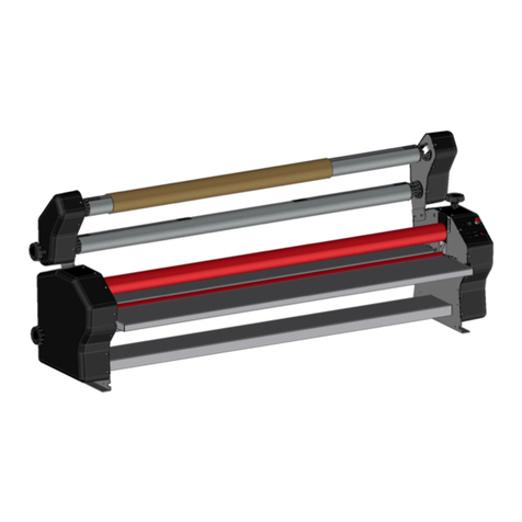
GBC 80-99 Installation and operation manual

GBC Pro - Tech
4151 Anderson Road
DeForest, WI 53532
Revision : Ph: ( 608 ) 246 - 8844
Fx: ( 608 ) 246 - 8645
ORCA 80-99 OPERATION
& MAINTENANCE MANUAL
© June 2000 GBC Pro-Tech
Do not duplicate without written permission.
Partnumber:930-055

Page I
Tableof ContentsOrca 80-99 Operation and Maintenance Manual
© GBC Pro - Tech June 2000
Table of Contents
Section 1: Safety
Safety features .............................................................................. 1 - 1
Section 2: Warranty
Limited warranty information ..................................................... 2 - 1
Exclusions to the warranty .......................................................... 2 - 1
Section 3: Specifications
Section 4: Installation
Uncrating ........................................................................................4 - 1
Uncrating Diagram........................................................................4 - 2
Electrical Requirements................................................................4 - 3
Suggested Layout...........................................................................4 - 4
Air Requirements...........................................................................4 - 5

Page II
Tableof Contents Orca 80-99 Operation and Maintenance Manual
© GBC Pro - Tech June 2000
Section 5: Operations
Operation....................................................................................... 5 - 1
Front control panel diagram........................................................ 5 - 2
Rear control panel diagram......................................................... 5 - 3
Front control panel....................................................................... 5 - 4
Rear control panel........................................................................ 5 - 4
Setup .............................................................................................. 5 - 5
Processes....................................................................................... 5 - 7
Process control chart (blank) ...................................................... 5 - 10
Process control diagram (blank)................................................. 5 - 11
Hot mount (Chart 2.2) .................................................................. 5 - 12
Hot mount (Diagram 2.2) ............................................................. 5 - 13
Hot mount/Laminate (Chart 2.3)................................................. 5 - 14
Hot mount/Laminate (Diagram 2.3)............................................ 5 - 15

Page III
Tableof ContentsOrca 80-99 Operation and Maintenance Manual
© GBC Pro - Tech June 2000
Encapsulation (Chart 2.4)............................................................ 5 - 16
Encapsulation (Diagram 2.4)........................................................5 - 17
Hot laminate/PSA mount (Chart 2.5)...........................................5 - 18
Hot laminate/PSA mount (Diagram 2.5)......................................5 - 19
Hot laminate/PSA mount (Second pass - Chart 2.6) ..................5 - 20
Hot laminate/PSA mount (Second pass - Diagram 2.6) ............5 - 21
Cold overlaminate/ PSA mount (Chart 2.7) ................................5 - 22
Cold overlaminate/PSA mount (Diagram 2.7) ............................5 - 23
Cold overlaminate/PSA mount (Second pass - Chart 2.8).........5 - 24
Cold overlaminate/PSA mount (Second pass - Diagram 2.8)....5 - 25
Cold laminate only using a sled (Chart 2.9) ................................5 - 26
Cold laminate only using a sled (Diagram 2.9)...........................5 - 27

Page IV
Tableof Contents Orca 80-99 Operation and Maintenance Manual
© GBC Pro - Tech June 2000
Section 6: Maintenence
Daily ................................................................................................6 - 1
Monthly...........................................................................................6 - 1
Six Month .......................................................................................6 - 2
Chain Diagram...............................................................................6 - 3

Page 1 - 1
SafetyOrca 80-99 Operation and Maintenance Manual
© GBC Films Group June 2000
SAFETY
READTHISSECTION BEFORE
OPERATINGTHEORCA80-99 LAMINATOR!
FOR YOUR SAFETY:
Yoursafetyaswellasthesafetyof others is important to
GBC Pro-Tech. In this instruction and on the product
are important safety messages. Read these messages
carefully.
1. Readalltheseinstructions.
2. Savetheseinstructionsfor later use.
3. Follow all warning and instructions marked on the
product.
4. Unplugthisproductfromthewalloutletbeforecleaning.
Do not use liquid cleaners or aerosol cleaners. Use a
dampclothforcleaning.
5. Do not use this product near water.
6. This product should be operated from the type of
powersourceindicated on the marking label. Ifyouare
notsureofthetypeofpoweravailable,consultyourdealer
ora qualified andcertifiedelectrician.
7. Donot allow anythingto rest onthe power cord. Do
not locate this product where persons will walk on the
cord.
8. Neverpushobjectsof any kind into this
productthrough any slotsas they maytouch dangerous
voltagepointsorshortoutpartsthatcould result in a risk
offireorelectricshock. Neverspillliquidof anykindon
theproduct.
9. Do not attempt to service this product yourself, as
openingorremovingcoversmayexposeyoutodangerous
voltagepointsorotherrisks. Referallservicingtoservice
personnel.
10. Unplug this product from the wall outlet and refer
servicingtoqualifiedservicepersonnelunderthefollowing
conditions:
A. When the power cord is damaged or frayed.
B. Ifliquidhasspilledintothe product.
C. If the product has been exposed to rain or water.
WARNING:
Never place fingers or arms between the rollers
whenthey are turningor whenthe rollers arein
theclosed position.
D. If the product does not operate normally when the
operating instructions are followed. Adjust only those
controls that are covered by the operating instructions
sinceimproper adjustmentofothercontrolsmay resultin
damageandwilloftenrequireextensiveworkbyaqualified
technicianto restore the product tonormal operation.
E. Iftheproductexhibitsadistinctchangeinperformance,
indicatinga need for service.
Safety Information
WARNING:
Itis vitalthat everyoneworking aroundthe
laminatorrollsavoidwearing loose-fittingclothing,
tiesordangling jewelrywhichcould becaughtin
thenip.
The GBC Pro-Tech laminator has been designed with
operator safety as a primary consideration. However,
operators must become thoroughly familiar with the
controls,andproper operation and safetyfeaturesofthe
machinebefore starting to use the unit.

Page 1 - 2
Safety Orca 80-99 Operation and Maintenance Manual
© GBC Films Group June 2000
GBCPro-Tech laminatorsarepowerfulmachines which
are designed to accomplish specific tasks such as
mounting, laminating and encapsulating. The forces
requiredtoaccomplishlaminatingcanvaryfromnegligible
to very large. The air-cylinder system used to provide
downwardpressureonthetoprolliscapableofproducing
forces greater than 1000 pounds (454 kg). This force
can be applied to any object that may be present in the
opening(called the nip) between the tworollers.
As a safety measure, the laminator is equipped with a
photoelectriceyesystem which stops the machine when
objects or hands are located in the nip area. Once the
blocking object is removed and the light beam is
reestablished,thelaminatorrollsresumeturning.
Operatorsshould use careinloweringthetoplaminating
rolland know howtoreactquickly in anemergency.The
laminatorroll UP-DOWNswitch is located onthefront
instrumentpanel labeled“LaminatorRollControls”on
theleft-hand side ofthe machine. Asthe name implies,
this switch controls the up and down motion of the top
laminatorroll. Before turning thisswitchto the DOWN
position,assure that nothing is in theniparea.
MostGBC Pro-Tech machinesare designed toheat the
laminationrollers. Temperatures canbe set toover 200
degrees F (100 degrees C). Thus there is a danger of a
severeburn if the
rollersare touched during set-up oroperation.
The machines have steel end cabinets that are bolted
closed. They serve to isolate the electrical- and drive-
systemcomponents.
WARNING:
Pleasenote: All personsworking on ornear the
Orca80-99 Laminatormust beadvised ofthe
following:
Ifany clothing, tools,or anything otherthan film
orpaperis inadvertentlydrawninto thenip,the
actionof therolls maybe halted immediately(and
thetop rolllifted) bypushing or strikingany ofthe
red E-Stop switches located at the top of the
machine,or bystepping onor kickingthe E-Stop
cablelocated at thebottom of themachine.
Quickaction in thisregard canaid in preventingor
minimizinginjuryormachinedamage.
Because of the electrical shock hazard and the
chance that a person might get either fingers or
clothing into the drive mechanism, the cabinets
shouldonly beopened byaqualified service person,
after the machine is shut off and the power
disconnected.

Page 2 - 1
Warranty
Orca 80-99 Operation and Maintenance Manual
© GBC Films Group June 2000
WARRANTY
LimitedWarranty
CAUTION:
Unauthorizedcustomeralterations willvoidthis
warranty.
GBCPro-Tech warrants the equipment sold is free from
defectsinmaterial and workmanship for a period of one
(1) year from the date of delivery to the customer.
This warranty is the only warranty made by Pro-Tech
andcan not be modified oramended.
GBCPro-Tech’s soleand exclusiveliability andthe
customer’s sole and exclusive remedy under this
warranty shall be, at GBC Pro-Tech’s option, to
repairorreplaceanysuchdefectivepartorproduct.
TheseremediesareonlyavailableifGBCPro-Tech’s
examination of the product discloses to GBC Pro-
Tech’s satisfaction that such defects actually exist
andwere not caused by misuse, neglect, attemptto
repair, unauthorized alteration or modification,
incorrect line voltage, contaminated air supply, or
byfire, accident orflood orotherhazard.
Thiswarrantyspecificallydoesnotcover damage to the
laminatingrollers caused byknives, razor blades,other
sharp objects, failure caused by adhesives or improper
useof the machine. Warranty repair orreplacementdoes
notextendthewarranty beyondtheinitialoneyear period
fromthe date of delivery.
THE WARRANTY MADE HEREIN IS IN LIEU
OFALL OTHERWARRANTIES, EXPRESS OR
IMPLIED, INCLUDING ANY WARRANTY OR
MERCHANTABILITY OR FITNESS FOR A
PARTICULAR PURPOSE. GBC PRO-TECH
WILL NOT BE LIABLE FOR PROPERTY
DAMAGE OR PERSONAL INJURY (UNLESS
PRIMARILYCAUSED BY ITS NEGLIGENCE),
LOSSOFPROFITOROTHERINCIDENTALOR
CONSEQUENTIAL DAMAGES ARISING OUT
OF THE USE OR INABILITY TO USE THE
EQUIPMENT.
Exclusions to the Warranty
Thiswarranty specifically doesnotcover:
1.Damagetothelaminatingrollerscausedbyknives,razor
blades, other sharp objects, or
failurecaused by adhesives.
2.Damagetothemachinecausedbylifting,tilting,and/or
anyattempt to position the machine otherthanrollingon
theinstalledcasters.
3. Improper use ofthe machine.

Page 3 - 1
SpecificationsOrca 80-99 Operation and Maintenance Manual
© GBC Films Group June 2000
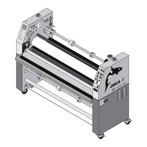
ORCA 80-99
SPECIFICATIONS
Description:
Floor-standinglaminatorwithmultipleunwind
positionsforhighproductivity heat-activatedlaminating,
encapsulating,heat transfer andmounting. The
laminatorcan alsobeusedwith pressure-sensitive films
forcoldmountingandlaminatingapplications.
Includes:
Outfeededgeslittersforinlinetrimmingoffinished
product.
Dimensions:
L - 120", D - 50", H - 66" (L- 3M, D- 1.27M, H-
1.68M)
Weight(uncrated):
2800 pounds (1270 kg)
LaminatingRolls:
86.5" length(220cm)roll facewiththermally
conductivesilicone coveredwithhighrelease silicone
surface,upper and lower rolls internally heated.
Temperaturecontrolledby state of the art infrared
sensorswithclosedloopdigital control systems,
independentlyadjustableforboth top and bottom rolls.
LaminatingOpening:
1_”(4.75 cm) maximumopeningcontrolledwithdual
aircylinders.
LaminatingMaterial:
Usesheat-activated 0-74” and pressure-sensitive
materials0-80" (0- cm) wide with films on3"(7.6
cm.)ID core.
LaminatingSpeeds:
0 to 30 fpm ( 0 to 9 Mpm) with variable speed,
reversibleaction, START and STOP controlled via the
frontinstrument-panel switchorwitha foot switch.
Unwind-Rewind:
Threeunwind positions; three rewind positions
Safety Features:
(1) Photo-eye motor stop, 4 emergency stop buttons
andtwo kick cablestostop the machineand raise rolls.
Warranty:
Oneyearpartswarranty(exceptsiliconerollcoverings
andtable tops).
Electric:
220 VAC, 50 or 60 Hz, single phase, 60-65 Amps.
Threephase32 Amps (Europe only).
CompressedAir:
2 CFM @ 100 PSI.

Page 4 - 1
InstallationOrca 80-99 Operation and Maintenance Manual
© GBC Films Group June 2000
INSTALLATION
UncratingtheMachine
CAUTION:
When taking the top off, care should be taken so
that the top does not fall into the crate, possibly
damagingthe laminator. It mightbe necessary to
use two or three people for this task.
During the uncrating process make sure thatthe
screws do not end up on the floor. They can cause
problemslaterwhen tryingtoroll themachineinto
position.
To uncrate the Orca 80-99 Laminator you will need a
phillipshead screwdriver. It helpstohave acordlessdrill
with the screwdriver bit, because there are quite a few
screwstoremovethroughoutthisprocedure. Inorder to
minimizethe possibilityofdamageto yournewOrca80-
99Laminator, please follow this procedure exactly.
1. The top of the crate is the first piece to be removed
(see diagram on page 4-3).
2. Next,remove one sideof the crate(see diagram). At
this point it is necessary to have someone support the
remainingsideofthecratewhiletheremainingendisbeing
removed. Maintainsupport of thesideuntilall mounting
screwsare removed andthe side isoff the crate.
3. Removethe end ofthe crate (seediagram).
CAUTION:
Donot use a knife or other sharpinstrument to
removeany protective covering. This could cause
irreparabledamageto themachine.
4. Remove the shrink wrap from the machine and its
contents.
5. Oncethe shrink wrapis off, removeany accessories
from the crate. While doing this, take care not to scuff
themachine.
6. Whenall the accessories have been removedfromthe
crate you will notice that there are two ramps that are
bolted down to the crate bottom: these will need to be
removed,using the phillipsheadscrewdriver.
Theramps must then besecuredto the edge ofthecrate
bottomusing the screwsleftoverfromcratedisassembly
(seediagram).
PLEASENOTE:The Orca80-99 Laminatorisa
largeand heavypiece ofmechanical equipment.
Casualmovement of equipment of this type canbe
hazardous to the average person; and poses the
potentialof serious damageto the machine.
It willbe necessaryto employqualified and
trainedpersonnel (licensed, certified RIGGERS)
ifany movement ofthe machine otherthan rolling
on a flat, level surface is contemplated.
TheOrca 80-99 Laminatoris not designedto be
tippedup or sidewaysin anyway. Suchaction may
disturbthe exactalignment of the rolling partsof
themachine andrequire extensivere-alignment.
GBCPro-Tech’s warrantydoes notcover
malfunctionofthe equipmentdueto mis-handling
and/ortipping.
GBCPro-Tech bearsno responsibility for parties
whofail tofollow these directions. Anyinjury or
damageto themachine dueto improper movingis
the sole responsibility of the mover.
Before the machine can be rolled off the crate, the foot
bolts must be freed from the four shipping hold-down
plates. Loosenthe lock-nut oneach of thefoot bolts.
Unscrewthe foot boltsfromthehold-down plates. Raise
butdonot removetheboltsandlocknutsfromthefoot
bracket.(Atthis time, you may wish to remove the hold-
downplatesfromthecratetoprovideunrestrictedremoval
ofthe machine from the crate).

Page 4 - 2
Installation
© GBC Films Group June 2000
Orca 80-99 Operation and Maintenance Manual
23in.
[59 cm]
3
2
INSTALL SCREWS
UNCRATING DIAGRAM
5
ORCA-80-99
1
4

Page 4 - 3
InstallationOrca 80-99 Operation and Maintenance Manual
© GBC Films Group June 2000
7. Oncetherampsaresecuredand the hold down plates
are removed, the machine can be rolled off the crate
bottom. Thiswillrequirefourpeoplehandlingthemachine
onitsfourcornersandcarefullyrollingthemachineoffthe
crate bottom (see diagram). The machine can now be
rolledinto its finaloperatingposition.

Choose a spot with sufficient space around the unit so
thatthere can be frontandbackworktables and adequate
spaceforefficientmaterialflow.Thus,atypicalroomarea
requirementfor the ORCA 80-99is 20 X 24feet (6.0 x
7.3 Meters) to allow use of work tables in front and to
therearofthemachine. See the suggested layout in Fig.
1-1 (page 4-4).
Once the Orca 80-99 Laminator has been placed in its
final position, optimum performance is obtained by
installing the supplied leveling pads and leveling the
machine. Install one leveling pad on each foot-bolt,
tighteningsecurely.
Lower the leveling padtothe floor by turningdownthe
footbolts. Turnalltheboltssufficientlyto lift all four of
thecastersoffthefloor.
CAUTION:
Some generation of static electricity is
unavoidableduringthe laminatingprocessdue to
thenature of the materials used. In order toavoid
anyhazard ofignition, fireor explosion dueto
staticspark, itis imperative that the operating
environmentis freeof dust,flammable liquids,and
vapors.
Then,face themachineandplace a carpenter’slevelleft-
to-righton one of the idlers. Adjust the bolts on the front
twofootbracketsso thatthemachineislevel left-to-right.
Then,movethelevel totherearofthemachineandadjust
thereartwolevelingpads.
Next,placethelevelfront-to-rearononeoftheaircylinder
brackets and adjust the bolts equally on the two foot
brackets on that side. Move the level to the other air
cylinder bracket and repeat the procedure for the other
side.
Afterbothsideshave beenleveledfront-to-back,goback
and check the side-to-side level condition of the front
andrearof the machine to insure thatithasnot changed.
If it has, repeat the procedure until the machine’sfront,
rear, and both sides are all level. Tighten the lock nuts
securelytothefoot brackets.
8. Atthis point a qualified electrician connectspowerto
themachine. Makesurebeforesupplypowerisprovided
thatthemachinecircuitbreakerisintheoffposition. This
is also the point where the appropriate supply of clean,
drycompressedairisconnectedtothemachine(seepower
andairrequirements).
ElectricalRequirements
TheORCA 80-99 isdesigned to accept220 to 240-volt
AC, 50/60-Hz, 60 Amps, single phase 3 wire (USA).
Thepeakpowerrequired by the unit is55 Amperes.Or,
in Europe only 3-N phase 230/400 VAC, 50 Hz, 25
Ampsper phase.
Beforeattempting toelectricallyconnect oroperateyour
newOrca80-99Laminator,aqualified,licensedelectrician
should be consulted to ensure that an adequate power
supply, having the appropriate capacity, overcurrent
protection,safetylockouts,etc.,isavailable;andtoensure
thatthepowersupplyof the Orca 80-99 is in accordance
withallestablishednational andregionalelectrical codes
andstandards.
CAUTION:
Theair supplyto theOrca mustbe cleanand dry
orthe machinewill bedamaged.
GBCPro-Tech, will not be responsible for damage
to the equipment caused by improper connection,
incorrectpowersupply orotherincorrect electrical
installation.
Beforeinitial power is appliedtothemachineassure that
all toggle switches on the front and rear control panels
andthemain power circuit breaker (inside/bottom of the
left-sidecabinet)areset to OFF. The AC connection is
locatedonthebottom/front of the left-side cabinet.

Page 4 - 4
Installation
© GBC Films Group June 2000
Orca 80-99 Operation and Maintenance Manual
SUGGESTED WORKSPACE
LAYOUT
Fig. 1-1
AIR SUPPLY
ELECTRICAL
SUPPLY
20' [6m]
24'[7.3m]
10'[3m]
4'[1.2m]
10' [3m] 3'
[1m
]
ORCA 80-99
FRONT
REAR
Work Table
6' X 6'
[2m x 2m]
(on wheels)
Work Table
6' X 6'
[2m x 2m]
(on wheels)

Page 4 - 5
InstallationOrca 80-99 Operation and Maintenance Manual
© GBC Films Group June 2000
Air Requirements
CAUTION:
Do not use a knife or other sharp object to remove
thepaper coverings. Thiswouldcause irreparable
damage to the rolls and necessitate their
replacement.
TheOrca80-99laminatorrequiresfilteredairat2cubic
feetper minute(CFM),(50liters/minute) atapressureof
at least 100 pounds (700 kPa) per square inch (PSI).
The air supply must be clean (free of dirt) and dry.
Moisture will cause corrosion and particles can block
pneumatic controls. Either can cause the laminator to
malfunction.
Itisthecustomer’sresponsibility to provide appropriate
filtersandwatertrapsfortheairlinebeforetheairisrouted
tothelaminator.
GBCPro-Tech suggeststhatthe best approach to theair
requirementis to provide a dedicatedsmall compressor
for the laminator. A standard light-duty 1/2 to 3/4
horsepower (1 kW) electric air compressor with 1.5 to
2.5 CFM output with a 2.5 - gallon (20 Liter) storage
tankis appropriate.
Airis fed to themachineviaa1/4-inch quick-disconnect
male connector. This connector is located below the
cabinet on the left side of the machine. (Once the air
supplyandelectricalpowerareconnectedtothemachine,
proceedtothe section on Operationinthismanual).
9. Next,remove the paper coveringsfromtheroll. After
the roll coverings have been removed, you will need to
openthe accessory pack. Theaccessory pack contains:
Qty Description
1Set,Allen wrenches
1Slittingknife
1Manual
1BottleofIsopropylAlcohol
1100% white cottonterry rags
1Set,spare fuses
2Additionalslitterknives
1T-handlewrench, 5/16"
1T-handlewrench, 1/4"
1MaskingTape
1TapeMeasure
1RubberCementPick-Up
1ShimSet
4LevelingPads
2OutfeedSlitters
2O-Rings,Brake
1Oil,AirTool
Theseitemsareneeded toputthemachineinto operation.
RECYCLINGINSTRUCTIONS:
Thecrate componentscanbe reusedfor shipping
themachine again,or maybe disassembledand
thewood andscrews recycled. Theshrink wrap
however, is not recyclable so therefore must be
discarded.
Inorder tobeginoperationof themachine,theUp/Down
ratesfor the mainand pull rolls andthe nips must beset
(seetheOperationsection of this manual). Once set, the
machineis ready for operation.

Page 5 - 1
OperationsOrca 80-99 Operation and Maintenance Manual
© GBC Films Group June 2000
OPERATION
Safety
Safetyisalwaystheprimaryconcern.Ifyouhavenot
readthe safety informationatthefront of thismanual,
dosonow. Do not attemptoperationof the machine
untilyoufullyunderstandthissafetyinformation.
GeneralPrecautions
1. Keep razor blades, knives, and all other sharp
objectsawayfrom the chrome and silicone rollers. They
areeasilydamaged and very expensive toreplace.
CAUTION:
Insertshims tokeep the laminating and pullrolls
apartwhen the machineis not inuse. Do notrely
onthe airsupply. Prolongedcontact candamage
therolls.
2.Harsh chemicals such as TolueneorMEKwill
destroythe silicone coveringonthelaminatingrolls.The
rollsshould be cleaned daily following theprocedure
outlinedin theMaintenancesection ofthismanual.
CAUTION:
Ifsilicone adhesives contactthe top orbottom roll,
removeit IMMEDIATELY using isopropyl
alcohol.Itwillhardenwithin an hour.
3. Donotallowliquidsiliconeadhesivestocontactthe
toporbottomsiliconeroll.Thesematerials will bond to
theroll in much less than onehour.Ifsomeadhesive
doesgeton the roll, wipe itoffIMMEDIATELY using
isopropylalcohol.
4.The laminatingrollswilldevelopflat spotsifleftin
contactwitheach other when not inuse.Alwaysinsert
theshimswhenshuttingoffthelaminator.Do notrelyon
theair supply to keepthe top roller intheraised
position,as the air supply can failatanytime.
5. Use a 100-percent cotton terry cloth to remove
heat-activatedlaminating residue, while the rolls arehot.
Followthisprocedureeverytime heat-activated
laminatesareused.
WARNING:
1. Never place fingers or arms between the
rollers,bothmain andpull, or inroller slotsno
matterwhat theoperational statusthe machineis
in.
2.It is vitalthat everyone workingaround the
laminatorrollsavoidwearing loose-fittingclothing,
tiesordangling jewelry,whichcould becaughtin
thenip.
WARNING:
Extracaution must beused whenoperatingthe
laminatorwiththe providedfootswitch. The foot
switchacts as an“over-ride” to thephotoelectric
eye;i.e., it allows the rolls to continueoperation
even if the photoelectric eye detects an
obstructionnearthenip.
Thisfunction isnecessary a)to allowinitial hand-
feeding of process materials to the rolls and b) to
prevent damage to the process at the end of a
sheet due to “curl-up” of the sheet end.
Operatorsare cautionedto use the foot switchfor
as short a time as practicable, and to exercise
cautionwhendoing so.

Page 5 - 2
Operations
© GBC Films Group June 2000
Orca 80-99 Operation and Maintenance Manual
ON
TOP CLUTCH CONTROLS
LAMINATOR ROLL CONTROLS
BOTTOM BRAKE CONTROLS
BOTTOM CLUTCH CONTROLS
TOP BRAKE CONTROLS
PRO-TECH ENGINEERING, MADISON, WISCONSIN380-3440
POWER
OFF ON
OFF ON
LIGHTS
PRESSURE
PRESSURE
OFF
OFF
PRESSURE
PRESSURE
OFF
OFF
PRESSURE
OFF
S
MOTOR CONTROLS
F
A
R
E
T
S
REV
R
E
0
L
W
STOP
FWD
JOG RUN
ON
ADJUST
ON
ADJUST
ADJUST
ON
ADJUST
ON
ADJUST
FRONT CONTROL PANEL
TOP UNWINDS (3)
ON/OFF
AIR PRESSURE
ADJUSTMENT
TOP REWIND
ON/OFF
UP/DOWN
LAMINATOR ROLL
ON/OFF
BOTTOM UNWIND
ON/OFF
BOTTOM REWIND
AIR PRESSURE
GAUGE
RUN/JOG
SWITCH
SWITCH
FORWARD/REVERSE
SPEED CONTROL
SEL RST
SPEED READOUT
ON/OFF
MAIN POWER
LAMP
PHOTOEYE
LAMP
BOTTOM HEATER SWITCH
ON/OFF LAMP
SWITCH
MAIN POWER
TOP HEATER SWITCH
ON/OFF LAMP
Fig. 2-1
(TOP BRAKE)
A
B
C
D
E
F
G
H
I
J
K
L
M
N
Photoeye
Blocked

Page 5 - 3
OperationsOrca 80-99 Operation and Maintenance Manual
© GBC Films Group June 2000
ADJUSTPRESSURE
BOTTOM CLUTCH
OFF ON
BOTTOM COOLING FANSTOP COOLING FANS
BOTTOM HEAT
OFF
TOP HEAT
ON
BOTTOM BRAKE
PULL ROLLER PRESSURE
PULL ROLLER CLUTCH
ADJUSTPRESSURE
ADJUSTPRESSURE
ADJUSTPRESSURE
ONOFF ONOFF
OFF ON
ONOFF
ONOFF
ONOFF
REAR CONTROL PANEL
BOTTOM HEATER
BOTTOM HEATER
CONTROL
ON/OFF
ON/OFF
BOTTOM FAN BANK
ON/OFF
TOP FAN BANK
ON/OFF
TOP HEATER
CONTROL
TOP HEATER
PULL ROLL CLUTCH
PRESSURE GAUGE
PRESSURE GAUGE
PULL ROLL
TENSION PRESSURE
BOTTOM UNWIND
BOTTOM REWIND
GAUGE
TENSION PRESSURE
GAUGE
PULL ROLL CLUTCH
ON/OFF
UP/DOWN
PULL ROLL
BOTTOM BRAKE
ON/OFF
ON/OFF
BOTTOM CLUTCH
AIR PRESSURE
ADJUSTMENT
ADJUSTMENT
AIR PRESSURE
ADJUSTMENT
AIR PRESSURE
ADJUSTMENT
AIR PRESSURE
ADJUSTMENT
AIR PRESSURE
Fig. 2-2
D
E
F
G
H
I
J
A
B
C

Page 5 - 4
Operations
© GBC Films Group June 2000
Orca 80-99 Operation and Maintenance Manual
OperatorControls
Theoperatorcontrols for the Orca laminatorare
operator position. See Figures 2-1 and 2-2. The names
andfunctions of these controls are asfollows:
FRONTCONTROLPANEL
Pleasenotethat in each ofthecontrolsections there is a
PressureGauge,anOn/Offswitchand an Air Pressure
Regulator. ThePressureGauge shows the operational
pressure. TheOn/Off switch turns the control function
onor off. The Air PressureRegulator adjusts the air
pressureforthecontrolfunction.
A.TOP BRAKECONTROLS - Regulationof the
upperunwindshaftbrakes.
B.TOP CLUTCH CONTROLS - Front upper rewind
shaftclutchregulation.
C.LAMINATOR ROLLCONTROLS - Regulationof
themainlaminatingrolls.
D.BOTTOM BRAKECONTROLS - Regulationof
thefrontlowerunwindbrake.
E.BOTTOM CLUTCHCONTROLS - Regulationof
theshaft’s lowerfrontrewindclutch.
F. RUN/JOG SWITCH - Changes control of the
machinedrivefromafootswitchoperationto
continuousrun. Italsoallowsthe operator to “Jog” the
rollsfor a short period oftime.
G. REV-FWD-This switch controls the directionof
thedrive system, forward orreverse.
H. SPEED CONTROL - Adjusts the speed of the
machinefrom zerotomaximumas thecontrolisturned
clockwise.
I.SPEED READOUT - Digital readout of the machine
speedandtotal throughput in eithermetricorstandard
units.
J. ON/OFF LAMP (Top Heater) - Denotes whether
thetop heater controller is onor off.
K. ON/OFF LAMP (Bottom Heater) - Denotes
whetherthebottom heater controller isonoroff.
L. PHOTO EYE LAMP - Denotes whether or not the
PHOTO EYE is blocked.
M. MAIN POWER LAMP - Denotes whether or not
themain power is on the machine.
N. MAIN POWER SWITCH - Turns the
mainpower on and off.
REARCONTROL PANEL
A.ON/OFF (Top Heater Controller) - Controls
whetheror not the top heatercontrolleris on or off.
B. TOP HEATER CONTROLLER - Controls the
uppermain roll’s operational temperature and provides
areadoutof the actual temperature.
C. ON/OFF (Top Fan Bank) - Controls whether or
notthe top fanbank is onor off.
D. ON/OFF (Bottom Heater Controller) - Controls
whetheror not the bottom heatercontroller is on or off.
E. BOTTOMHEATER CONTROLLER - Controls
thelower main roll’s operational temperature and
providesa readout of the actualtemperature.
F. ON/OFF (Bottom Fan Bank) - Controls whether or
notthe bottom fan bankison or off.
G. PULL ROLLER CLUTCH CONTROLS-
Regulationforthebottompullrollerclutch.
CAUTION:
Usetheminimumlaminator rollpressure
consistent with good results. Excess pressure can
damagethelaminating rollers.

Page 5 - 5
OperationsOrca 80-99 Operation and Maintenance Manual
© GBC Films Group June 2000
H. PULL ROLLER PRESSURE CONTROLS -
Regulationforthe upper pull roll pressure and up/down.
I. BOTTOM BRAKE CONTROL - Regulation for
thebottom rear unwind brake.
J. BOTTOM CLUTCH CONTROL - Regulation for
thebottom rear rewind shaft’s clutch.
Setup
Setupof the Orca laminatorisquickand
straightforwardwheninstructionsare followeddirectly.
WhenyoufirstreceivetheOrca Laminator the nips
mustbe set beforeoperation. The procedures for
settingthemain and pull roll nips areonpages8-1 and
8-2.
LaminatorRollPressure:
1. Youshould useonlythe minimumamountofroll
pressureneeded to accomplish the task.While higher
nippressure can make the adhesivebond faster, excess
pressurecandamage the rollers. Wrinkles, bubblesand
suchhave causes that generally cannot becuredwith
morepressure.
2.A typical roll pressure forsoftsubstrates such as
Foamcore or Orca-Board is between 20 to 30 pounds
per square inch (PSI) or 32 to 205 kPa.
3.Therangeof typical values for hardsubstrates is25
to 50 PSI, 170 to 345 kPa.
LoadingtheFilm
Filmis loaded on the appropriate unwinds.Instructions
laterinthissectionwillcoverloadingand aligningfilm.
Forapplications suchasencapsulation,filmwill befed
fromboth top and bottom unwinds.
Theprocess of loading andaligningfilmisthe same for
boththe top andthe bottom. Thereare two important
pointstorememberwhenloadingfilm:
CAUTION:
Assurethat film is always mountedso that the
adhesivesidewill faceoutwardfrom the
laminatingroller.
1.The adhesive side of the film must be oriented away
(onthe outside)ofthelaminating roller.Otherwiseitwill
immediatelybondtothe roller, creatingamajorclean-
upproject. Films have a shinyside and a dullside. The
dullsideis the one with the adhesive. Thus, the dull side
shouldALWAYS faceoutwardfromthe laminatingroll.
2.The film must be centered on the unwind for best
performance.Thisisvitalwhentwofilmsare fed
together.Ifthetwofilmsarenot aligned, feed problems,
wrinkles,excessglue on rolls and otherassorted
troubleswillresult.
CAUTION:
Unlessthe two filmsfed to thenip are carefully
aligned,poor results will be seen.
PositioningFilm
Thefollowingprocedureisapplicableto both the top
andthe bottom feed unwinds:
1.Remove the balldetentretainingpinsandcarefully
removethe unwind/rewind shaft from its saddles. Pay
particularattention to the drive sidesaddles. Thedrive
sideof the shafts must be oriented so as to not pry on
the brake or clutch protrusion. To doso would
irreparablydamageboth brakes and clutches.
2. Slidethe film onto the unwind shaft.
3.Install the shaft back into its saddles again paying
carefulattentiontothedrivesideend of the shaft.
Returnballdetentpinsto secure the shaft in its saddles.

Page 5 - 6
Operations
© GBC Films Group June 2000
Orca 80-99 Operation and Maintenance Manual
4. Centerthefilmbyslidingitback and forth on the
shaftuntil centered. As soon as the filmisunwound
fromtheshaft, the core support will lock the roll into
position.
5.Recheck the centering of the film roll with a tape
measure.
WARNING:
Normaloperation of theOrca 80laminator
involvesthe application of large amountsof heat
to the process materials. The surfaces of the rolls
areat ahigh enoughtemperature tocause burnsif
theyare touched.
Operatorsare cautionednot totouch, leanor fall
againstthe rollsof an operatinglaminator. Do not
becomeunbalancedwhenworking nearan
operatinglaminator.
Heating
Thefollowinginstructionsshould beemployedwhen
heatingone orbothofthe laminatingrolls.The
procedureis the samefor top andbottom:
1. Set the heater switch to ON.
2.Adjustthe temperature controller for thedesired
operatingtemperature using the controller push
bottoms.
Forthe Syrlec typecontroller use theup and down
arrows to adjust the set point. Hold down the desired
arrowuntilthe correct set point isachieved.
For the CAL3200 it is necessary to press the *button
atthe same time as the up or down arrow to adjust the
setpoint temperature.
3.When heating therolls,keep the toproll down and
turningata moderate speed to prevent uneven heating.
4.Itwilltakeapproximately25minutesforthe
laminatingroller(s) to reachoperatingtemperature.
Whenthe pre-set operatingtemperature has been
reached,the machine is readyto use.
Cooling
(withoptionalcoolingfans)
Thefollowing procedure is the fastest waytocool
downthemachine.Natural cooling can also be
employed:
1.Set the heaterswitches to OFF.
2.Position the tworear fan banksso that they are tilted
todirect air flow at therolls.
3.Set the LaminatorRoll Control tothe DOWN
position.
4.Set theForward/Reverse switch tothe FORWARD
position.
5.Set the speed control to 5 fpm (150 cpm).
6.Letthemachinerununtilthelaminating rollsreturnto
roomtemperature.
PaperTips
1.Always cut the leadingedgeofa print straight so they
canbe fed perpendicular to the laminatingrolls.
ProcessControlCharts
Chart 2-1 and 2-1B show a blank set of process
controlcharts for theORCA 80. Thesecharts are
whereyourecordthewayyouthread film through the
machine’srolls and idlers(calledwebbing)andthe
settingofcontrols and switches foreachproductand
process.
GBCPro-Tech laminators respond inavery accurate
andrepeatable manner. Thecharts provide a wayto set
upeachtime,everytime,forrepeatableperformance
byassuringall controls are set to optimum.
This manual suits for next models
1
Table of contents
Other GBC Laminator manuals

GBC
GBC 56FM User manual

GBC
GBC Fusion Plus 7000 L Instruction Manual

GBC
GBC FOTON 30 Automated Laminator Instruction Manual

GBC
GBC 2080WFt User manual

GBC
GBC PRO-TECH DS-60 User manual

GBC
GBC fusion 1100L User manual

GBC
GBC ORCA III T Manual

GBC
GBC Pinnacle 27 EZload User manual

GBC
GBC F-36 Operating instructions

GBC
GBC Inspire A4 Instruction Manual